

Abstract
This paper presents design, hardware, software, and parameter optimization for a novel robotic automation system. RABiT is a Rapid Automated Biodosimetry Tool for high throughput radiological triage. The design considerations guiding the hardware and software architecture are presented with focus on methods of communication, ease of implementation, and need for real-time control versus soft time control cycles. The design and parameter determination for a non-contact PVC capillary laser cutting system is presented. A novel approach for lymphocyte concentration estimation based on computer vision is reported. Experimental evaluations of the system components validate the success of our prototype system in achieving a throughput of 6,000 samples in a period of 18 hours.
1 INTRODUCTION
The development of advanced methods for radiation biodosimetry is becoming a top priority need for the protection of environment and homeland security against possible radiological or nuclear attacks [1]. Because the general population would not carry physical dosimeters, a rapid method due to the large number of individuals to be scored which locates the individuals who were exposed and would benefit from aggressive antibiotic treatment at lower dose or bone marrow transplant within one week is needed. Other than these individuals who are very few in a radiological dispersion device (RDD) scenario, there will be very many “worried well” people who think they were exposed but were not. The rapid tool is able to free up valuable medical resources and to assist in curbing mass panic.
In the past decade, many researchers have been working on designing a fully automated ultrahigh throughput biodosimetry system, based on robotic material handling and high speed imaging systems. Meldrum et al. demonstrated a capillary-based fluid handling system, ACAPELLA-5K (A5K), capable of processing genomic and chemical samples at a throughput of 5,000 preparations in 8 hours [2]. Kachel et al. designed a custom-made automated system capable of isolating DNA plasmids at a rate of 1,600 plasmids in 12 hours [3]. Prasanna et al. reported on the automation of cytogenetic biodosimetry featuring a throughput of 500 samples per week [4]. Soldatova et al. commissioned a new robotic system for investigations of gene function in capable of handling more than 1,000 samples a day [5]. These attempts were directed toward automating the imaging system rather than the biological processing itself.
This paper presents our ongoing efforts in the design, hardware and software integration, and experimental evaluation of a phase I high throughput biodosimetry system. The RABiT automates two mature biodosimetry assays (micronucleus [8] [9] and γ-H2AX[10]), both of which have been shown to be highly radiation specific. The use of mature assays is critical for timely deployment, because FDA pre-marketing requirements are much less time-consuming than for a new bio-assay. Lymphocytes, a type of white blood cells in human immune system, are extracted from blood samples into filter well plates through an automation system (Figure 1). The system consists of several modules: input stage, centrifuge, cell harvesting module, service robot, liquid/plate handling, incubator, high-speed imaging system, and central master controller.
Figure 1.
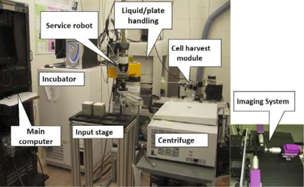
System breadboard prototype.
The blood samples are collected with a finger stick using a standard lancet (Figure 2a). The volume of each sample is 30μl. Blood is drawn into heparin-coated PVC capillary (RAM Scientific, Safe-T-Fill capillaries). The capillary is then loaded into a centrifuge bucket insert, prefilled with sealing putty and separation medium. The blood samples remain stable for 48 hours in the capillary at ambient conditions. The insert can be used for shipping the sample from the collection site to the RABiT where it is manually loaded into a centrifuge bucket on the input stage. Each bucket (Figure 2b) holds 3 inserts containing 32 capillaries each. For each time, four buckets are transferred from input stage (Figure 2c) to centrifuge (Figure 2d). After centrifugation at 4,000 rpm for 5 minutes, the lymphocytes are separated from Red Blood Cells (RBCs) (see Figure 2e). After the PVC capillary is cut by a laser machine, the bottom part with RBCs is disposed. The lymphocytes in the upper part are dispensed in a well plate (Figure 2f). Then after 72 hours incubation and staining, samples on filter bottoms of the well plate are transferred to imaging substrate and sealed (Figure 2g). Finally, the substrate is delivered to the imaging module, where dedicated image hardware measures yields of micronuclei or γ-H2AXfoci, already well-characterized quantifiers for radiation exposure.
Figure 2.
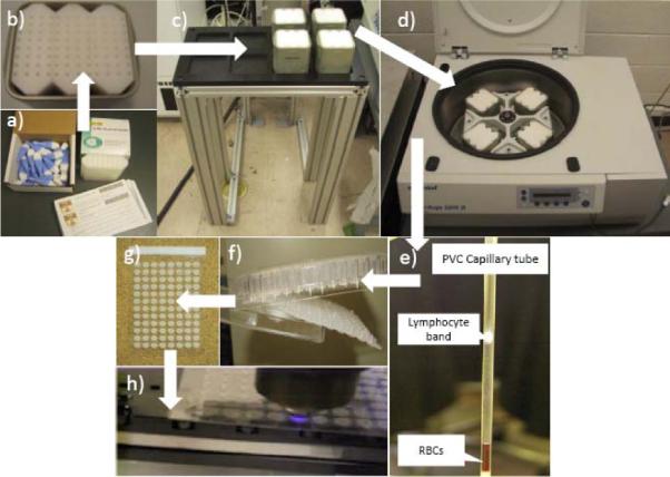
Lymphocyte separation of blood sample sequence.
The following sections present hardware design and implementation, software architecture and experimental performance validation of the system prototype.
2 HARDWARE AND IMPLEMENTATION
Figure 3 shows the three-tier hardware architecture of the RABiT. The top tier is the central master controller. The middle tier includes all system components in direct communication with the central master controller. The bottom tier includes system peripherals controlled by secondary controllers of the equipments in the middle tier.
Figure 3.
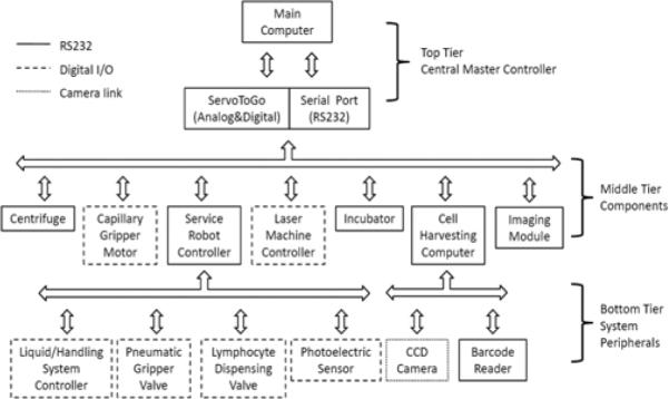
Hardware architecture.
The central master controller has two types of communication protocols. One is based on serial communication protocol, while the other is based on Digital & Analog I/O card (ServoToGo, ISA Bus Servo I/O Card Model 2). This I/O card has 32 bits of digital I/O, 8 channels of 13-bit analog input, and motion control ports for up to 8 differential TTL encoder signals.
The centrifuge is able to work with partial load. When working with a rotor which is not completely loaded, the tubes are transferred to the centrifuge within the buckets in such a way that the rotor pivots are stressed evenly (Figure 4a). The centrifuge (Eppendorf, 5810R) incorporates a customized interface board, a lid opener and a brake (Figure 4b) such that through 5 bits of digital I/O, the central master controller is able to take full robotic actions: open lid, load buckets, close lid, start centrifugation, stop centrifugation, open lid and unload buckets. When the centrifuge stops, the service robot moves to the center of the rotor of the centrifuge, rotates 360 degree and then detects the orientation of the rotor ribs using a photoelectric sensor (Figure 4b, Banner Engineering, QS18VN6FF100) mounted on the robot's end arm.
Figure 4.
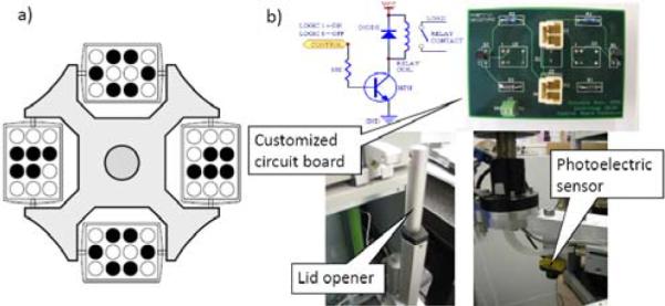
Centrifuge tube balancing position and electronic components.
The PVC capillaries containing separated blood are handled by a customized gripper (Figure 5a). A multi-purpose pneumatic gripper (Figure 5b, SMC, MHF2-20D2) is used to pick, drop centrifuge buckets and well plates. The pneumatic gripper is controlled by a 4-way valve for air (Arozone, A212SS-O24-D-G 10197). The air pressure stays on 0.5MPa to achieve 12.1N of gripping force. The capillary gripper (Figure 5a) use a DC motor (Maxon, with a gear head and a 2-channel differential magnetic encoder) to control the rotation of its shaft. By one motion control channel of ServoToGo, the central master controller sets the reference voltage to the motor servo amplifier (Maxon, LSC30/2). Position feedback is implemented based on the encoder feedback at 1kHz. A customized capillary holder at cutting position (Figure 6) will hold bottom part of the capillaries while rotating to reduce the wobbling. Section III in [6] describes the details of gripper design for the RABiT.
Figure 5.
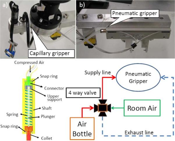
Multi-purpose material handling gripper.
Figure 6.
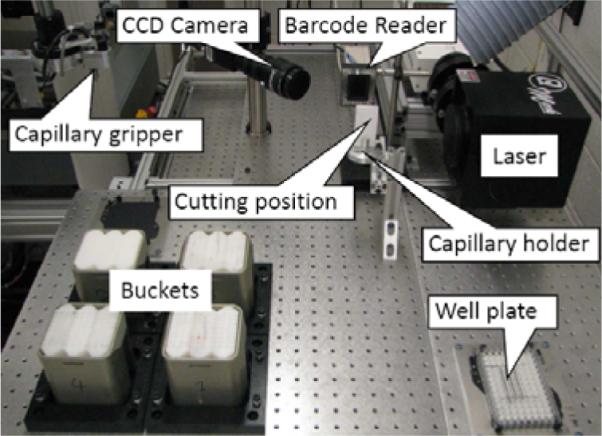
Cell harvesting module.
The service robot (Staubli, RS80) communicates with its controller (Staubli, CS8C) by Can Bus. The central master controller always sends commands to the robot controller through a serial RS232 communication port. CS8C has 16 bits of digital input and 16 bits of digital output, which are used to control the peripheral devices that directly interface with the service robot (Figure 3). The liquid/handling system (CaliperLS, Sciclone ALH3000) takes 4 bits of digital input and 4 bits of digital output to communicate with the service robot such that robot can monitor the operation status of the Sciclone. Each of the pneumatic gripper valve and the lymphocyte dispensing valve take 1 bit of digital output from the robot controller CS8C based on digital I/O signals originating from the central master controller. The photoelectric sensor also takes 1 bit of digital input.
The communication between the central master controller and the laser machine uses RS232 serial communication. By sending character `1' or `0', the laser will turn the laser beam on or off. The parameters of the laser beam, such as laser power, and pulse frequency, are preset in the Windows-based controller of the laser machine.
The communication between the central master controller and the incubator is also based on RS232 protocol. After the central master controller sends a command to the incubator, the incubator will execute it and then send a status signal back to the central master controller. The central master controller can require the incubator to import or export a well plate, report its status, and read temperature/humidity of the incubator cabinet.
2.1 Cell Harvesting
The cell harvesting module (Figure 6) processes incoming samples after centrifugation. Each PVC capillary is processed with the purpose of extracting only the lymphocytes into a 96-well plate for subsequent liquid handling.
The cell harvesting module consists of an ultra violet (UV) laser machine (Quantronix, Osprey-355-1-0), a barcode reader (Siemens, Hawkeye 1525HD), a CCD camera (JAI, CVM4+CL), and custom-made holders for capillaries, multi-well plates and centrifuge buckets.
Initially the service robot picks centrifuged buckets from the centrifuge. Then the capillary gripper is used to pick up individual capillaries. As the diameter of the capillaries varies within a batch from 2.10mm to 2.14mm, the capillary gripper was designed to allow for variations in the diameter and achieved a successful picking of over 99% of the capillaries. This design implements a compliant rubber seal that accommodates diameter variation of the capillaries.
The capillary is then moved into the field of view of the barcode reader for identification. Since the barcode etched on the capillary (Figure 7) is small (2.0mm×10.0mm), reliability of the barcode reader is important. However, repeating the reading process 3 times results in a success rate of 95% based on using code 128 for the barcode. After that, the capillary is moved into the field of view of the CCD camera. The CCD camera interfaces with the cell harvesting windows computer via a camera link connection and a frame grabber (NI, NI-1426) such that the cell harvesting computer is able to capture pictures and transfer the picture data quickly. Then imaging programs based on NI Vision will analyze the picture to detect the position of the separation band between the culture medium and the red blood cells.
Figure 7.
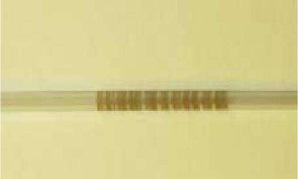
Barcode on the capillary.
In the following, the service robot moves down or up to align the separation band with the laser focal point. Then the robot sends `ready' signal to the central master controller. The central master controller turns on the capillary gripper motor with 40rpm for 3.0s, and sends `1' to the laser machine to turn on the laser beam at the same time. After laser cutting, the bottom part with red blood cells drops in the disposing box. The upper part is positioned by the service robot above the well plate in order to dispense the lymphocytes in the well plate.
2.2 Laser Cutting
The advanced UV laser is to realize non-contact cutting with the goal of eliminating cross-contamination among samples. The output power of the laser beam is 1.1W with 355nm wavelength, 20kHz pulse repetition frequency and 40μm of the effective spot size, thus the laser fluence is 4.377 J/cm2. As to PVC absorption rate in [7], absorbed pulse energy of 266nm wavelengths is 18.33μJ, and the laser fluence at the focal plane becomes 1.46J/cm2. Since the PVC ablation rate is 2.5μm/pulse [7], the thickness of the capillary is 0.5mm, so there should be at least 200 laser pulses of 0.01s duration to cut off the capillary. The corresponding rotation speed of the capillary gripper is 35.7rpm. This ensures circumferential cutting of the PVC capillaries. The optimal cutting time is 1.65 seconds.
The laser focus is located at the middle of tube wall with best cutting quality. Because the lymphocytes are usually 13mm away from the cutting position, calculated by heat transfer modeling (3D flow considered all directions are infinity except along thickness direction), the temperature distribution at the lymphocytes does not change remaining the room temperature while cutting. Since the safe temperature for lymphocytes is 45°C, the lymphocytes of blood samples are not damaged by the heat from laser cutting. The quality of laser cutting of PVC capillary tubes depends on the choice of effective parameters, including average laser power, motor rotation speed and cutting time. By analyzing the capillaries after cutting, such as change of inner diameter, outer diameter and thickness, dross attachment and resolidification, and visible discoloration with burning, the cutting quality can be determined. Figure 8 shows the pictures of cross-sectional views of the sliced capillaries as seen under an optical microscope.
Figure 8.
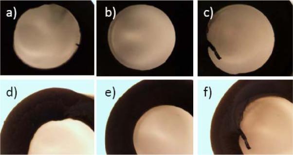
(a), (b) Cross-section views of capillary cut at 0.8W and 30rpm; (c), (d): 0.8W and 40rpm and (e), (f): 0.8W and 50rpm.
The cutting quality under different power and rotation speeds are shown in Table1. The quality is classified from `0' to `5' with `0' designating worst and `5' presenting best cut quality. We can see that the optimal speed is 40rpm and the laser power is 0.8W. So the time of one-turn rotation is 1.5s. Since the ideal cutting time is 1.65s, we require the gripper motor to rotate two full turns to ensure full cutting of the capillary. Thus the cutting time used in our system is 3.0s per capillary. In 96-tube laser cutting test, 95% tubes were cut successfully.
Table 1.
Cutting quality.
| Power (W) | |||||||
|---|---|---|---|---|---|---|---|
| Speed (rpm) | 0.4 | 0.5 | 0.6 | 0.7 | 0.8 | 0.9 | |
| 30 | 0 | 2 | 2 | 2 | 3 | 0 | |
| 40 | 0 | 0 | 3 | 4 | 4 | 0 | |
| 50 | 0 | 0 | 0 | 3 | 3 | 3 | |
| 60 | 0 | 0 | 0 | 0 | 0 | 2 | |
| 65 | 0 | 0 | 0 | 0 | 0 | 3 | |
| 70 | 0 | 0 | 0 | 0 | 0 | 0 | |
2.3 Lymphocyte Concentration Estimation
In the event of a large scale radiological event, there will be a need to quickly evaluate lymphocytes using the biodosimetric assays since this could otherwise lead to a delay in treatment of severely irradiated patients. The RABiT first triages incoming samples before laser cutting based on the concentration of the lymphocytes in centrifuged capillaries. There is no analytical method to achieve the lymphocyte concentration threshold value for severely irradiated patients yet. We will collect threshold data through the test on irradiated blood samples in the future.
A novel, rapid quantitative light absorption analysis (QLAA) method has been developed to characterize lymphocyte concentration instead of quantitative buffy coat analysis (QBCA). The principle of light absorption in material is followed by Beer-Lambert Law. The incident light beam from a LED array light source is collimated by a customized collimator. Right after transmitting through capillary tube, the light is collimated by another narrow collimator. Behind the second collimator, a CCD camera is used to image the capillary and measure the light intensity by calculating grayscale of the image. In experiment, we extracted the light absorption of lymphocytes by measuring the light transmittance of the separation medium and the separated lymphocytes, respectively.
Experiments tested the light absorption intensity calibration curves with different lymphocyte concentration (Figure 9). After blood separation, lymphocyte cells form a compact, high concentration band in capillary tube. In such case, light absorption analysis method is very useful to characterize the lymphocyte concentration. To determine the absolute lymphocyte cell number in the lymphocyte band and calibrate our system, we used a standard hemocytometer. The calibration curves have been extracted out based on the 30μl whole blood sample volume and 3000 lymphocyte cells per μl (compared to the 4000~10000cells/μl is the average range of fresh healthy human blood). One difficulty in calibrating light absorption curve is that we cannot find enough patients and health people, which represent different irradiation levels. Another bottleneck is that since the volume of collected blood samples is small - 30μl, it is hard for current devices to separate and count them efficiently. The five-point calibration curve shown in Figure 9 is the best result we have obtained. We will continue to look for ways to achieve better calibration results for lymphocyte estimation.
Figure 9.
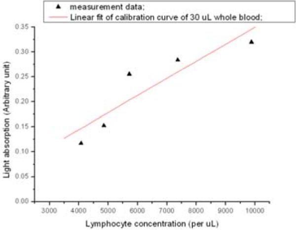
Lymphocyte calibration of light absorption.
2.4 Imaging Module
After the lymphocytes are dispensed on the bottom of the well plate, the well plate is transferred to the liquid/plate handling system (CaliperLS, Sciclone ALH3000) and the incubator (Liconic, STX220) for 72-hour incubation and staining. In the following, the bottom substrate of the well plate is sealed and transferred to the imaging module. The high speed imaging module is developed to analyze the images of each assay in the sealed substrate to find the lymphocyte concentration. Figure 10 shows the imaging module. To meet the high throughput requirements, the imaging module incorporates three novel techniques for speeding up the imaging: use of light steering rather than sample motion, single-step auto-focusing and parallel use of multiple high-speed cameras.
Figure 10.
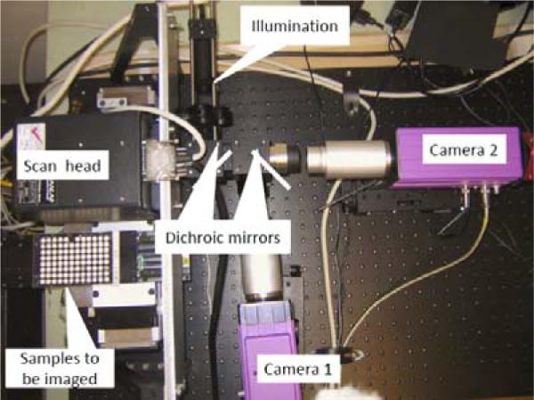
Imaging module prototype with two cameras for imaging DAPI and cell mask orange.
To achieve sufficient evaluation statistics, over one hundred 200-μm frames (fields of view) need to be imaged for each sample. Typically, imaging different frames within the same sample is achieved by mechanically moving the stage. However, mechanical motion takes tens of milliseconds, which is too slow. Instead of moving the sample, the light is steered into the camera using fast galvanometric mirrors. Typical transit times between adjacent fields of view are less than 1 msec.
One-step focusing is performed by incorporating an astigmatic element (a cylindrical lens) into one component of the optics. We take an image and adjust the objective distance using a piezo actuator (settling time 20msec). Spherical beads are added to assist in focusing. This results in a known focus-dependent distortion. For example, a spherical bead is imaged as an ellipse, and the aspect ratio of the ellipse indicates exactly how far the sample is out of focus. Figure 11 shows observed aspect ratio of a 4 μm fluorescent bead as a function of distance from focus using a cylindrical lens with a focal length of 500 mm.
Figure 11.
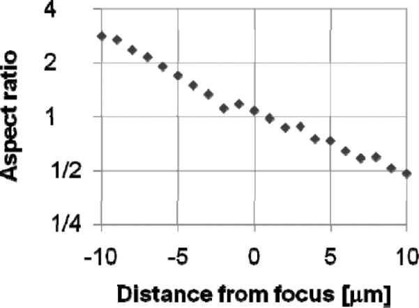
Observed aspect ratio.
Multiple cameras, sensitive to the colors of different dyes, allows simultaneous acquisition of separate images of the nucleus (stained using DAPI)and either the cytoplasm (stained using Cell Mask Orange) or γ-H2AXfoci (stained with Alexa fluor 555), as well as focus information.
3 SOFTWARE ARCHITECTURE
The RABiT system has three computers, and three machine controllers. Their operating systems and programming environments are listed in Table 2.
Table 2.
System controller and programming.
| Computer And Controller | Operating System | Programming Tool |
|---|---|---|
| Main Computer | Linux Fedora 8.0 with RTAI 3.6 | GCC 4.1, Qt designer 4.4 |
| Cell harvesting Computer | Windows XP | VC++ 2005 |
| Service Robot Controller | Windows XP | VAL3, Staubli Robotic Studio 3.1 |
| Laser Machine Controller | Windows XP | Quantronix DC2.2 |
| Liquid/Handling System Controller | Windows XP | Sciclone Workstation 3.5 |
| Imaging Module Computer | Red Hat Enterprise 5.2 | gcc 4.1.2 and Matrox Imaging Library 9.0 |
The central master controller is allocated for real-time application (kernel space) and non-real-time applications (user space). The classification of the system devices and their use of kernel space or user space memory are tabulated in Table 3. Real-time devices, for example, the capillary gripper motor, use 1kHz control loop frequency with closed-loop PID control. Non-real-time devices are instruments with a secondary dedicated controller where the application does not require a frequent real-time update of control reference signals.
Table 3.
Device classification.
| Device | Real-time | Non-real-time |
|---|---|---|
| Centrifuge | Yes | |
| Capillary Gripper Motor | Yes | |
| Service Robot Controller | Yes | |
| Laser Machine Controller | Yes | |
| Incubator | Yes | |
| Cell harvesting | Yes | |
| Imaging module | Yes |
4 EXPERIMENTAL RESULTS
4.1 Throughput Analysis
To meet the throughput requirements, we measured the time cost of the various steps of the capillary handling protocol shown in Figure 1. Table 4 is the time spent on each system modules. The total time for each sample is 11.06 sec, which means a throughput of 5859 samples in an 18-hour duty cycle.
Table 4.
Completion times for major steps in the sample preparation protocol.
| Step | Time (sec) | |
|---|---|---|
| Total | Per sample | |
| Load four buckets into centrifuge | 97.5 | 0.25 |
| Centrifugation | 370.0 | 0.96 |
| Unload centrifuge | 52.8 | 0.14 |
| Transfer one multi-well plate from stack to dispense position | 6.80 | 0.07 |
| Cell harvesting handling | 9.64 | 9.64 |
| Total time | 11.06 | |
The window for treatment is one week, which is much larger than the usual turn-around time in the RABiT - 72hours. Other actions, like incubation, imaging, are parallel to the actions listed in Table 4. Thus we do not need consider the time spent on these actions when we evaluate the throughput of the RABiT. The timing of the cell harvesting module takes 90% of the whole sample handling timing. Its sequential actions are pick one capillary, take a picture and locate lymphocyte band, move robot down to align the separation region between RBCs and separation medium in front of the laser, cut capillary, read barcode, dispense the lymphocyte, dispose of tube. Table 5 is the completion times of each action.
Table 5.
Completion times of each action of cell harvesting.
| Action | Time (sec) |
|---|---|
| Capillary picking | 2.01 |
| Imaging and cutting capillary | 5.12 |
| Lymphocyte dispensing and capillary disposing | 2.51 |
| Total time | 9.64 |
4.2 Lymphocyte Concentration and Radiation Exposure Dose Evaluation
Assays can be simplified to the detection of `blobs and holes', rather than more complex morphometric structures, and thus the image analysis stages are very rapid. Analysis of the cytokinesis-block micronucleus assay is demonstrated in Figure 12. The raw images (Figure 12 a,b,d,e) are filtered and binarized, and a watershed algorithm is applied to separate touching objects. Then the two binary images (of nuclei and cytoplasms) are analyzed in conjunction with each other; the binarized image of the nuclei (Figure 12 a,d) is subtracted from the binarized image of the cytoplasms (Figure 12 b,e) and the nuclei belonging to each cell are identified in the subtracted image (Figure 12 c,f). The RABiT software then scores the number of micronuclei (small holes) in binucleated cells (those with two large holes). Thus, by the relation curve (Figure 13) between radiation exposure dose and micronuclei number, the radiation exposure dose will be evaluated.
Figure 12.
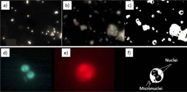
Sample image analysis
Figure 13.
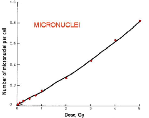
Radiation exposure dose calibration
5 CONCLUDING REMARKS
This paper reported the design, hardware, and software considerations for a Phase I robotic prototype of the high throughput bidosimetry system. This system integrates contactless laser machining, high-speed imaging, and custom-designed robotic components for a fully automated handling of incoming PVC capillaries. The experimental evaluation of this Phase I system shows its capability to process 5859 samples in an 18-hour duty cycle.
Future work is focused on increasing the throughput of this system by cutting down on the time delay during the various cell harvesting stages. Our efforts towards achieving these goals include optimized higher speed laser cutting of the PVC capillaries and integration of custom-designed robot for handling individual capillaries during the various stages of cell harvesting. This approach will allow parallel processing of samples during the cell harvesting stages.
6 ACKNOWLEDGEMENTS
This work was supported by the NIH-funded Center for High-Throughput Minimally-Invasive Radiation Biodosimetry (NIAID Grant U19 AI067773).
Contributor Information
Youhua Chen, Department of Mechanical Engineering Advanced Robotics and Mechanism Applications Research Laboratory, Columbia University, New York, NY 10027, U.S.A..
Jian Zhang, Department of Mechanical Engineering Advanced Robotics and Mechanism Applications Research Laboratory, Columbia University, New York, NY 10027, U.S.A..
Hongliang Wang, Department of Mechanical Engineering Advanced Robotics and Mechanism Applications Research Laboratory, Columbia University, New York, NY 10027, U.S.A..
Guy Garty, Center for Radiological Research Advanced Robotics and Mechanism Applications Research Laboratory, Columbia University, New York, NY 10027, U.S.A..
Yanping Xu, Center for Radiological Research Advanced Robotics and Mechanism Applications Research Laboratory, Columbia University, New York, NY 10027, U.S.A..
Oleksandra V. Lyulko, Center for Radiological Research Advanced Robotics and Mechanism Applications Research Laboratory, Columbia University, New York, NY 10027, U.S.A.
Helen C. Turner, Center for Radiological Research Advanced Robotics and Mechanism Applications Research Laboratory, Columbia University, New York, NY 10027, U.S.A.
Gerhard Randers-Pehrson, Center for Radiological Research Advanced Robotics and Mechanism Applications Research Laboratory, Columbia University, New York, NY 10027, U.S.A..
Nabil Simaan, Department of Mechanical Engineering Advanced Robotics and Mechanism Applications Research Laboratory, Columbia University, New York, NY 10027, U.S.A..
Y. Lawrence Yao, Department of Mechanical Engineering Advanced Robotics and Mechanism Applications Research Laboratory, Columbia University, New York, NY 10027, U.S.A..
D. J. Brenner, Center for Radiological Research Advanced Robotics and Mechanism Applications Research Laboratory, Columbia University, New York, NY 10027, U.S.A.
7 REFERENCE
- [1].Pellmar TC, Rockwell S. Priority list of research areas for radiological nuclear threat countermeasures. Radiation Research. 2005;163:115–123. doi: 10.1667/rr3283. [DOI] [PubMed] [Google Scholar]
- [2].Meldrum DR, et al. Sample Preparation in Glass Capillaries for High-Throughput Biochemical Analyses. International Conference on Automation Science and Engineering; Edmonton, Canada. 2005. [Google Scholar]
- [3].Kachel V, Sindelar G, Grimm S. High-throughput isolation of ultra-pure plasmid DNA by a robotic system. BMC Biotechnology. 2006;6(9) doi: 10.1186/1472-6750-6-9. [DOI] [PMC free article] [PubMed] [Google Scholar]
- [4].Prasanna PGS, et al. Technical Report. (AFRRI CD 05-2) Armed Forces Radiobiology Research Institute; 2005. Cytogenetic Biodosimetry for Radiation Disasters: Recent Advances. [Google Scholar]
- [5].Soldatova LN, et al. An ontology for a robot scientist. Bioinformatics. 2006;22(14):464–471. doi: 10.1093/bioinformatics/btl207. [DOI] [PubMed] [Google Scholar]
- [6].Salerno A, Zhang J, Bhatla A, Lyulko OV, Nie J, Dutta A, Garty G, Simaan N, Randers-Pehrson G, Yao YL, Brenner DJ. Design considerations for a minimally invasive high-throughput automation system for radiation biodosimetry. 3rd Annual IEEE Conference on Automation Science and Engineering.2007. pp. 846–852. [Google Scholar]
- [7].Gedvilas Mindaugas, Račiukaitis Gediminas. Investigation of UV picosecond laser ablation of polymers. Proc. of SPIE. 2005;6157(61570T) [Google Scholar]
- [8].Fenech M, et al. HUMN project: detailed description of the scoring criteria for the cytokinesis-block micronucleus assay using isolated human lymphocyte cultures. Mutat Res. 2003;534:65–75. doi: 10.1016/s1383-5718(02)00249-8. [DOI] [PubMed] [Google Scholar]
- [9].Cytogenetic analysis for radiation dose assessment: A manual. International Atomic Energy Agency; Vienna: 2001. [Google Scholar]
- [10].Nakamura A, et al. Techniques for γ-H2AX detection. Methods Enzymol. 2006;409:236–250. doi: 10.1016/S0076-6879(05)09014-2. [DOI] [PubMed] [Google Scholar]