Abstract
We proposed and fabricated multiscale transparent arteriole and capillary vessel models with circular cross sections of 10–500 μm using photolithography. The circularities of the fabricated 10, 50, and 500 μm diameter microchannels were 84.0%, 61.5%, and 82.3%, respectively. Next, we connected these different models to realize a circulation type blood vessel model simulating arteriole networks. We proposed a novel connection method using an intermediate connector made of wax, which we used to connect these models to make a circulation model. In flow experiments, the fabricated models showed no leakage and circulation models with seamless connections were achieved.
INTRODUCTION
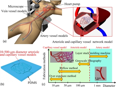
Surgical simulators are used in practice and rehearsal for intravascular neurosurgery and for the development of new medical instruments, such as catheters. In conventional surgical simulators, blood vessels are larger than 500 μm in diameter. Smaller blood vessel models are needed in order to simulate a more realistic vessel environment such as diameters and branching structures, as shown in Figs. 1a, 1b. We developed custom three-dimensional (3D) elastic membranous blood vessel models with 3D wax models fabricated by ink-jet rapid prototyping.1, 2 Then, we developed a transparent surgical simulator by connecting the elastic membranous models. However, models less than 500 μm in diameter are very difficult to fabricate using ink-jet rapid prototyping because of the brittleness of the wax. Diseases also exist in blood vessels such as arteria basilaris that are narrower than 500 μm in diameter. Previous surgical simulators are not suitable for rehearsal and training for such diseases. The present study is an attempt to fabricate multiscale-diameter transparent arteriole and capillary vessel models that enable easy simulation of blood circulation. The diameter of the capillary vessel is 10 μm. For this purpose, we must fabricate microchannels with circular cross sections of 10–500 μm.3
Figure 1.
Blood vessel simulator with arteriole and capillary vessel models. (a) Concept of the circulation type blood vessel simulator. (b) Example of arteriole and capillary vessel models. The diameters of these microchannels are 10–500 μm. (c) Concept of multiscale fabrication for transparent blood vessel models.
Numerous methods, such as machining, stereolithography, ink-jet rapid prototyping, and photolithography, have been proposed for the fabrication of microchannels. Machining is suitable for straight channels of up to approximately 10 μm in diameter but not for complicated capillary vessel networks. Stereolithography, although applicable for the fabrication of molds, has difficulty in creating hollow structures. Although ink-jet rapid prototyping is useful for custom 3D thicker channels, such as aortas, it is not applicable for capillary vessel models. Photolithography is a fundamental technology for fabricating microchannels, and a high resolution of 1 μm is easily attained.4, 5 We have chosen photolithography for fabricating the arteriole and capillary vessel models.6 In general, fabricating microchannels that have circular cross sections is quite complex.7, 8, 9, 10 Microchannels have been fabricated using semicircular photoresist patterns and light curable resin, but the cross sections of the fabricated channels were semicircular.11, 12 These processes are not suitable for fabricating fine blood vessel models. Therefore, we proposed a new fabrication process for multiscale transparent arteriole and capillary vessel models. The target microvessel models must have a circularity of over 52.4% because the circularity of the narrowest real blood vessel is 52.4%.13 The circularity can be calculated by dividing the shortest axis by the longest axis.
The fabricated arteriole and capillary vessel models were connected with conventional blood vessel models in order to realize a circulation simulator. For example, circulation models will enable the simulation of animal testing and drug delivery systems using microvessels. In the present paper, we report the fabrication methods and prototyping results for the circulation models.
ARTERIOLE AND CAPILLARY VESSEL MODELS
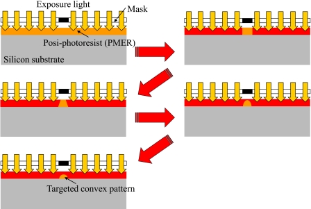
We proposed multiscale fabrication methods for blood vessel models [Fig. 1c]. The processes used were overexposure, reflow, grayscale lithography, and ink-jet rapid prototyping using a layer stack molding machine. Among these processes, photolithography processes such as overexposure, reflow, and grayscale lithography are used to construct fine structures. In the present paper, overexposure means that the coated photoresist is exposed until the recommended exposure doses at soft-contact are exceeded. The soft-contact distance between the mask and a resist sample is 10–20 μm. The exposure light is diffracted by the mask pattern. We can obtain a semiround resist pattern by diffracted light exposure, as shown in Fig. 2. Reflow is a well-known process used to construct the convex photoresist patterns. In the reflow process, the developed resist pattern is heated from the back side of substrate. Then, the resist becomes a liquid again, and the semiround resist pattern is realized by liquid surface tension. Grayscale photolithography is a method that can be used to produce 3D resist patterns. In general, the grayscale mask uses shading to control the histogram and is very expensive. In the present study, the grayscale mask is produced using a 1∕20 reduction machine with a film mask that has 256 tones. We easily obtain this grayscale mask, which is then used to construct the arteriole models. After exposure, the fabricated photoresist patterns are transcribed onto poly(dimethylsiloxane) (PDMS).14 Arteriole and capillary vessel models having circular cross sections are generated by bonding two patterned PDMS substrates using plasma treatment and heating [Fig. 3a].15 Here, we fabricated arteriole and capillary vessel block models using photolithography processes.16, 17
Figure 2.
The mechanism of overexposure using diffracted light. PMER is very sensitive to light exposure. Within the definite range of the recommended exposure amount, the cross section of the resist patterns is square. The shape of the cross section of the resist pattern varies as trapezoidal, triangular, semiround, and oval by increasing the amount of light exposure.
Figure 3.
Concept and results of constructing a capillary vessel model. (a) Concept of plasma bonding. After plasma treatment, two patterned PDMS substrates are aligned and bonded by heating, and the capillary vessel model is realized. (b) Cross section of the capillary vessel model channel (before improvement).
We used overexposure, reflow, and grayscale lithography to produce fine convex structures. However, due to limitations of resolution of the various fabrication methods, it is necessary to choose an appropriate method to fabricate a model with target diameter. For example, capillary vessel models (diameter: 10 μm) are fabricated by the overexposure method, arteriole models (20–100 μm in diameter) are fabricated by the reflow method, and arteriole models (diameter: 100–500 μm) are fabricated by grayscale lithography.18 The fabrication process flow is as follows:
-
(A)Overexposure method for capillary vessel models with 10 μm diameter microchannels
-
(1)A substrate is coated with 8-μm-thick posi-photoresist PMER (Tokyo Ohka Kogyo Co., Ltd.).
-
(2)The substrate is exposed at hard contact points using both a mask and a resist sample until 1000 mJ∕cm2.
-
(3)The substrate is developed for 7 min.
-
(4)The substrate is hard baked at 145 °C for 30 min.
-
(5)After the plasma-hydrophilic treatment, the substrate is coated with 8-μm-thick photoresist PMER.
-
(6)The substrate is exposed at hard contact points using both the mask and the resist sample until 1000 mJ∕cm2.
-
(7)The substrate is developed for 7 min.
-
(8)The substrate is hard baked at 145 °C for 30 min.
-
(9)After plasma-hydrophilic treatment, the substrate is coated with 8-μm-thick photoresist PMER.
-
(10)The substrate is overexposed at soft-contact points using both the mask and the resist sample until 1500 mJ∕cm2.
-
(11)The substrate is developed for 5 min.
-
(12)The photoresist pattern is transcribed onto PDMS.
-
(1)
-
(B)Reflow method for arteriole models with 20–100 μm diameter microchannels
-
(1)A silicon substrate is coated with posi-photoresist PMER.
-
(2)The substrate is exposed until 1000 mJ∕cm2.
-
(3)The substrate is developed for 7 min.
-
(4)The resist patterns are heated at 145 °C from the bottom for 30 s using a hot plate.
-
(5)The resist patterns are transcribed onto PDMS.
-
(1)
-
(C)Grayscale lithography for arteriole models with 100–500 μm diameter microchannels
-
(1)A glass substrate is coated with nega-photoresist SU-8 (Kayaku Co., Ltd.).
-
(2)The substrate is exposed from the bottom until 1200 mJ∕cm2. [Mask data are shown in Fig. 5d.]
-
(3)The substrate is developed for 30 min.
-
(4)The resist patterns are transcribed onto PDMS.
-
(1)
Figure 5.
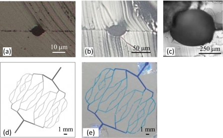
Cross sections of the fabricated models. (a) 10 μm diameter microchannel, (b) 50 μm diameter microchannel, (c) 500 μm diameter microchannel, (d) grayscale mask data for the 100–500 μm diameter arteriole network model, and (e) results of a check for leakage of the fabricated arteriole network model.
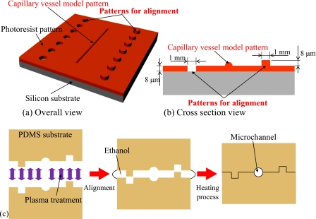
We previously fabricated a branched capillary vessel block model with a diameter of approximately 10 μm having a nearly circular cross section. However, the channel cross section was slightly out of alignment [Fig. 3b]. To solve this problem, we fabricate a capillary vessel model and alignment patterns for the assembly using multistage exposure photolithography, as shown in Figs. 4a, 4b.
Figure 4.
Designed photoresist patterns for alignment and circular cross section capillary vessel model. (a) Overall view. (b) Cross section view. (c) Alignment and plasma bonding process.
After exposure and transcription, each patterned surface of the two patterned PDMS substrates is treated by plasma. Next, two plasma-treated PDMS substrates were finely self-aligned using the surface tension of ethanol. Finally, the aligned substrates were heated at 120 °C for 20 min [Fig. 4c]. These processes create arteriole and capillary vessel models having circular cross sections. Figures 5a, 5b, 5c show the cross sections of the fabricated arteriole and capillary vessel models. Next, an arteriole network model was fabricated based on the theoretical equation for the branched structure of real blood vessels given as follows:
| (1) |
where R0 is the diameter of the vessel before branching and R1 and R2 are the diameters of the vessels after branching. The diameters calculated using Eq. 1 are shown in Table 1.19 We calculated the circularities of 10, 50, and 500 μm diameter microchannels by dividing the shortest axis by the longest axis and obtained 84.0%, 61.5%, and 82.3%, respectively. In addition, we evaluated the alignment accuracy of the arteriole and capillary vessel models. For the 10 μm diameter capillary vessel model, a model having no alignment pattern (old-type model) had an alignment error of 2.5 μm, whereas a model with alignment patterns (new-type model) had an alignment error of 0.6 μm. The circularity of the old-type model was 70%, and that of the new-type model was 84%. Thus, the alignment patterns reduced the alignment error from 2.5 to 0.6 μm and improved the circularity from 70% to 84%. For the 50 μm diameter arteriole model, the alignment error was 1.6 μm. For the 500 μm diameter arteriole model, the alignment error was 13 μm.
Table 1.
Calculated diameters of the network model.
| Daughter diameter (input value) | Mother diameter (calculated value) | |
|---|---|---|
| R1 (μm) | R2 (μm) | R0 (μm) |
| 100 | 100 | 125 |
| 125 | 125 | 159 |
| 159 | 159 | 200 |
| 200 | 200 | 252 |
| 252 | 252 | 317 |
| 317 | 317 | 400 |
| 400 | 400 | 504 |
For leakage check of the arteriole model channels, we disembogued methylene blue solution. From this experiment, fabricated channels were confirmed that they had no fluid leakage [Fig. 5e].
CIRCULATION TYPE BLOOD VESSEL MODELS
The circulation model was constructed of arteriole network models, artery models, and connector models made of wax. The arteriole network model has 100–500 μm diameter microchannels. Moreover, the diameter of the smallest artery model is 5.0 mm.
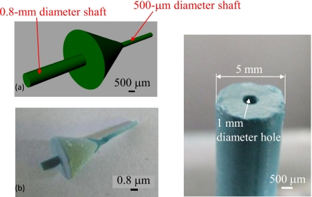
In the indirect connection method, we used wax connector models for seamless connection of the 500 μm diameter microchannel of the arteriole network and the 5.0 mm diameter macrochannel. The designed and fabricated wax connector model is shown in Fig. 6a. This connector was fabricated by ink-jet rapid prototyping and had shafts for aligning the central axis of each channel, as shown in Fig. 6b. A 500 μm diameter shaft was inserted into the network model channel, and a 0.8 mm diameter shaft was used to introduce the wax models into the artery model. We made a 1.0 mm diameter hole in the wax model of the artery for insertion and alignment, as shown in Fig. 6c. The connection process flow is summarized as follows:
-
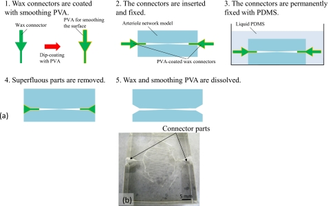
(A)Connection process for the network model [Fig. 7a]
-
(1)The wax connector is dip coated with polyvinyl alcohol (PVA) to smooth the surface.
-
(2)The connector is inserted into the 500 μm diameter microchannel of the network model and is temporarily fixed with PDMS.
-
(3)After temporary fixing, the connector permanently fixed with PDMS.
-
(4)The superfluous PDMS mold is removing.
-
(5)The wax and smoothing PVA are dissolved.
-
(1)
-
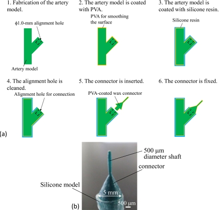
(B)Connection process for an artery model [Fig. 8a]
-
(1)A wax model with a 1.0 mm diameter alignment hole is fabricated by ink-jet rapid prototyping.
-
(2)The surface of the wax model is smoothed by dip coating with PVA.
-
(3)The wax model is dip coated with silicone resin.
-
(4)The silicone resin and PVA are removed from the alignment hole.
-
(5)The 0.8 mm diameter shaft of a PVA-coated connector is inserted into the alignment hole.
-
(6)The wax connector is fixed to the alignment hole with PVA.
-
(1)
Figure 6.
Designed and fabricated wax connector and artery model. (a) Designed connector. (b) Fabricated connector. (c) Artery wax model with a 1 mm diameter hole for connection.
Figure 7.
Connection process for the network model. (a) Connection process flow. (b) Network arteriole model with the connector.
Figure 8.
Connection process for the artery model. (a) Connection process flow. (b) Connector with the silicone model.
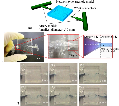
Figure 7b shows a model constructed of wax connectors and the network model. Figure 8b shows a model constructed using a wax connector and a wax model for an artery model. These models were connected in order to construct the circulation model. We coated the taper shape part of the wax connector with PDMS, connected the prepared network model and artery model with the coated wax connector. Then, we heated and connected them at 55 °C for 1 h. This assembly process produced the circulation model. Figure 9a shows the final connection process and the fabricated circulation blood vessel model. The fabricated model had a fine and seamless structure throughout [Fig. 9b].
Figure 9.
Circulation type blood vessel model. (a) Conceptual figure of the circulation model. (b) Fabricated circulation model and connected channel portion of the arteriole network model and wax connector. (c) Results of flow experiments using methylene blue solution. The flow rate is 1 μl∕min.
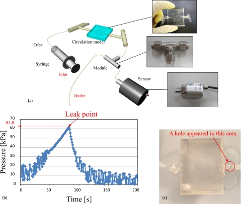
For evaluation of leakage check, we performed flow experiments with the fabricated circulation model using a methylene blue solution. The experimental results are shown in Fig. 9c. The flow rate was 1 μl∕min (this flow rate was 0.016 mm∕s in the 500 μm diameter microchannel), and the experiment demonstrated that these channels had no leakage. We also confirmed that the methylene blue solution flowed from the inlet to the outlet. The connected parts between the arteriole network model and artery models exhibited no leakage. The proposed method was suitable for fabricating circulation models. Next, a pressure test was conducted using the fabricated circulation model. Figure 10a shows the pressure test setup. The prepared pressure sensor can measure the liquid pressure. First, the microchannels of the circulation model were filled with de-ionized water. The outlet part was sealed off in order to increase the pressure inside the circulation model by the syringe pump (KDS120, kd Scientific). The output voltage decreased as the pressure inside the circulation model increased. The peak voltage indicates pressure of the circulation model when the leak started. The experimental results revealed that the leak pressure was approximately 61.8 kPa as shown in Fig. 10b. The leak point was located on the artery model, as shown in Fig. 10c. The pressure resistance of the fabricated circulation model was confirmed to be larger than the pressure of actual blood vessels. For example, the pressure in the artery is 16 kPa, and that in the arteriole is 13 kPa.20 Therefore, the results of the pressure test using the fabricated circulation model show that our model is capable of withstanding the pressures of real blood flow. Next, the pressure loss across the inlet and outlet of the fabricated circulation model was measured. This experiment required the use of two pressure sensors. One sensor was used to measure the pressure at the inlet side, and the other sensor was used to measure the pressure at the outlet side. The pressure loss was obtained by subtracting the pressure measured at the outlet side from the pressure measured at the inlet side. The pressure measured at the inlet side was 9.43 kPa and that measured at the outlet side was 9.18 kPa. Thus, the pressure loss was 250 Pa. This pressure loss may be caused by a high friction coefficient of silicone resin and PDMS and the length and structure of the channels. This pressure loss was sufficiently small. Moreover, this is not problematic, because the surfactant was added to the water used in the blood vessel simulator in order to decrease the friction coefficient of silicone resin and PDMS. However, when we culture cells in microchannels treated with surfactant, the surfactant harms cells. Instead, the inner surfaces of the channels should be coated with a chemical agent such as Cytop (Asahi Glass Co., Ltd.) for cell culture.
Figure 10.
Setup and results of a pressure test conducted with the fabricated circulation model. (a) Setup for pressure tests. (b) Relationship between time and pressure. The leak pressure was 61.8 kPa. (c) Leak point of the fabricated circulation model.
CONCLUSIONS
We have presented a method for fabricating 10–500 μm diameter transparent arteriole and capillary vessel models and circulation type blood vessel models. Fabricated arteriole and capillary vessel models are required the selection of an appropriate exposure method. Moreover, the fabricated circulation type blood vessel model simulates an arteriole network.
In fabricating block models, we improved the shape of the channel cross section with alignment patterns, which are very useful in assembling arteriole and capillary vessel models. We calculated the circularities of the fabricated 10, 50, and 500 μm diameter microchannels as 84.0%, 61.5%, and 82.3%, respectively. From the results of the methylene blue flow test, fabricated microchannels were confirmed that they had no fluid leakage.
In fabricating circulation models, we proposed and demonstrated arteriole network and artery models constructed by ink-jet rapid prototyping. A circulation model was then fabricated using a wax connector. We prepared a network model, artery models, and wax connectors. The connection method used herein had the advantage of easy connection and good alignment accuracy. The fabricated model had a fine and seamless structure, and the flow experiments revealed that the model had no leakage between the connected parts and channels. We also confirmed that the fabricated circulation model could withstand pressures of up to 61.5 kPa. The proposed connection method was suitable for fabricating circulation models. The fabricated circulation model will be used to evaluate drug delivery systems, diacrisis, and medical treatments by ultrasound.
ACKNOWLEDGMENTS
The present study was supported by a Grant-in-Aid for Scientific Research from the Ministry of Education, Culture, Sports, Science, and Technology of Japan and the Japan Society for the Promotion of Science (Grant Nos. 17076015, 18206027, and 214059).
References
- Ikeda S., Arai F., Fukuda T., Negoro M., and Irie K., J. Rob. and Mechatronics 17, 327 (2005). [Google Scholar]
- Ikeda S., Arai F., Fukuda T., Negoro M., Irie K., and Takahashi I., Proceedings of MICCAI 2005, LNCS 3749, Palm Springs, California, USA, 2005, pp. 925–932. [DOI] [PubMed]
- Hayashi K., Biomechanical Engineering: A First Course (Maruzen Co., Ltd., Tokyo, 1997). [Google Scholar]
- Noda D., Matsumoto Y., and Setomoto M., International Symposium on Micro-Nano Mechatronics and Human Science, Nagoya, Japan, 2007, pp. 436–441.
- Itoga K., Yamato M., Kobayashi J., Kikuchi A., and Okano T., Biomaterials 25, 2047 (2004). 10.1016/j.biomaterials.2003.08.052 [DOI] [PubMed] [Google Scholar]
- Borenstein J. T., Terai H., King K. R., Weinberg E. J., Kaazempur-Mofrad M. R., and Vacanti J. P., Biomed. Microdevices 4, 167 (2002). 10.1023/A:1016040212127 [DOI] [PubMed] [Google Scholar]
- Hanai K., Shimizu S., and Matsumoto Y., IEEJ Trans. Sens. Micromachines 125, 424 (2005). 10.1541/ieejsmas.125.424 [DOI] [Google Scholar]
- Eisner M. and Schwider J., J. Soc. Photo-Opt. Instrum. Eng. 35, 2979 (1996). [Google Scholar]
- Erdmann L. and Efferenn D., J. Soc. Photo-Opt. Instrum. Eng. 36, 1094 (1997). [Google Scholar]
- Nicolas S., Dufour-Gergam E., Bosseboeuf A., Bourouina T., Gilles J. -P., and Grandchamp J. -P., J. Micromech. Microeng. 8, 95 (1998). 10.1088/0960-1317/8/2/013 [DOI] [Google Scholar]
- Futai N., Gu W., and Takayama S., Adv. Mater. (Weinheim, Ger.) 16, 1320 (2004). 10.1002/adma.200400595 [DOI] [Google Scholar]
- Lin B. -C. and Su Y. -C., Proceedings of μTAS, San Diego, California, USA, 2008, pp. 86–88.
- Attinger E. O., in Pulsatile Blood Flow, edited by Attinger E. O. (McGraw-Hill, New York, 1964), Vol. 179. [Google Scholar]
- Wu M. -H., Park C., and Whitesides G. M., Langmuir 18, 9312 (2002). 10.1021/la015735b [DOI] [Google Scholar]
- Whitesides G. M., Ostuni E., Takayama S., Jiang X., and Ingber D. E., Annu. Rev. Biomed. Eng. 3, 335 (2001). 10.1146/annurev.bioeng.3.1.335 [DOI] [PubMed] [Google Scholar]
- Nakano T., Tada M., Lin Y. -C., Ikeda S., Uchida T., Oura H., Fukuda T., Matsuda T., Negoro M., and Arai F., Proceedings of International Symposium on Micro-Nano Mechatronics and Human Science, Nagoya, Japan, 2007.
- Arai F., Nakano T., Tada M., Lin Y. -C., Ikeda S., Uchida T., Oura H., Fukuda T., Matsuda T., and Negoro M., J. Rob. and Mechatronics 19, 535 (2007). [Google Scholar]
- O’Shea C. and Rockward W. S., Appl. Opt. 34, 7518 (1995). 10.1364/AO.34.007518 [DOI] [PubMed] [Google Scholar]
- Sherman T. F., J. Gen. Physiol. 78, 431 (1981). 10.1085/jgp.78.4.431 [DOI] [PMC free article] [PubMed] [Google Scholar]
- Whitmore R. L., Rheology of the Circulation (Pergamon, Oxford, 1968). [Google Scholar]


