Abstract
A single photon emission computed tomography (SPECT) imaging system can be modeled by a linear operator H that maps from object space to detector pixels in image space. The singular vectors and singular-value spectra of H provide useful tools for assessing system performance. The number of voxels used to discretize object space and the number of collection angles and pixels used to measure image space make the matrix dimensions H large. As a result, H must be stored sparsely which renders several conventional singular value decomposition (SVD) methods impractical. We used an iterative power methods SVD algorithm (Lanczos) designed to operate on very large sparsely stored matrices to calculate the singular vectors and singular-value spectra for two small animal pinhole SPECT imaging systems: FastSPECT II and M3R. The FastSPECT II system consisted of two rings of eight scintillation cameras each. The resulting dimensions of H were 68921 voxels by 97344 detector pixels. The M3R system is a four camera system that was reconfigured to measure image space using a single scintillation camera. The resulting dimensions of H were 50864 voxels by 6241 detector pixels. In this paper we present results of the SVD of each system and discuss calculation of the measurement and null space for each system.
Keywords: Singular Value Decomposition, SPECT, Sparse Matrix, Lanczos
1. INTRODUCTION
In the absence of detector noise a linear imaging system can be simulated using the mapping
| (1) |
We model f (r) using a voxelized representation such that
| (2) |
where φn(r) is a voxel function and fn is the nth component of the N × 1 vector f. Using this representation the continuous-to-discrete operator  is transformed into an M × N matrix operator H. Thus we model a linear system as
| (3) |
where for a SPECT model, f is an N × 1 vector representing the discretized radioisotope activity distribution of an object, H is a M × N matrix that contains the system response to object space, and g is an M × 1 vector of the image data. It should be noted that modeling errors occur when using a voxelized object representation. We will not addresss these modeling errors in this paper. Linear systems can be characterized using the singular vectors and singular-value spectra of H. The singular value decomposition of H can be expressed as
| (4) |
where H is rank R ≤ min (M, N), U is an M × M matrix whose columns are the object space singular vectors, V is an NxN matrix whose columns are the image space singular vectors, and D is an MxN diagonal matrix whose non-zero elements are equal to the singular values, μi. The singular vectors ui and vi form an orthonormal basis in object space and image space respectively. The diagonal elements of D form the singular-value spectra of the imaging system.
Numerous algorithms have been developed to calculate the SVD of a dense matrix that can be stored within computer memory. Unfortunately algorithms of this type cannot be applied to SPECT systems because the memory needed to store a dense representation of H will exceed the amount available to typical computer resources. This can be seen by considering the dimensions of H for an arbitrary SPECT system. The column dimension, N, is the number of voxels used to discretize object space. For a given object space a larger value of N implies a more thorough characterization of the system response to the object space. The row dimension, M, is the product of the number of detector pixels per camera P, the number of cameras C, and the number of collection angles A, for the system. A dense representation of H will therefore have P·C·A·N elements. For the systems discussed in this paper this product is on the order of 109 corresponding to the storage of gigabytes of data in memory.
For pinhole SPECT systems a useful property of H is that it will contain numerous zero valued elements. It is therefore advantageous to store H as a sparse matrix. Several iterative algorithms exist that can estimate the SVD for large sparse matrices. For this study we chose to use an algorithm known as the Lanczos method. The Lanczos method is efficient for large sparse matrices because the memory storage requirements are small and because fewer arithmetical operations are needed than for its counterparts. This paper presents the singular vectors and singular-value spectra attained using the Lanczos method on the FastSPECT II and M3R small animal pinhole SPECT systems. We also discuss characterization of SPECT systems by using the SVD data to calculate the null space and measurement space for a given object.
2. LANCZOS METHOD
The Lanczos method is a process used to compute the eigenvalues and eigenvectors, collectively referred to as the eigenelements, of a real symmetric sparse matrix. There are many good references such as Cullum1 and Sehmi2 that discuss the origins, mathematics and theory of the Lanczos method. The implementation of the algorithm used in this study was based on an ANSI C software package created by Berry3 et al. at the University of Tennessee. The fundamental algorithm is the Lanczos recursion which converts a real symmetric matrix A into a family of real symmetric tridiagonal matrices Tj. The eigenelements of Tj can be computed using standard techniques and can then be used to approximate the eigenelements of the original real symmetric matrix A. The Lanczos method therefore replaces the computation of the eigenelements of A with the simpler computation of the eigenelements of Tj.
2.1. Equivalent Eigenvalue Problems
A real symmetric matrix can be defined by the condition A = A†. For SPECT systems H is typically a non-symmetric matrix for which we desire the singular values and singular vectors. To compute the SVD of H using the Lanczos method we must therefore define an equivalent eigenvalue problem for a real symmetric matrix associated with H. One method for achieving this equivalence is to create the N × N matrix H†H or the M × M matrix HH† which yields the following eigenvalue equations
| (5) |
| (6) |
Operating on Eqn.(5) from the left with H yields the following relationship between eignevectors ui and vi
| (7) |
where we have included a normalization factor of . It can be shown that ui and vi form orthonormal bases in the Hilbert space associated with either eigenvector.4 It follows that we can construct the SVD of H as
| (8) |
where H is rank R, are the singular values of H, and {ui,vi} are the singular vectors of H. The set {μi, ui, vi} will be referred to as the singular system of H. To summarize, we can calculate the SVD of the M × N matrix H by computing the eigenelements of the real symmetric matrix H†H thereby facilitating use of the Lanczos method.
2.2. Lanczos Recursion
The Lanczos recursion generates a family of tridiagonal matrices Tj from the real symmetric matrix A for which we are trying to compute eigenelements. A tridiagonal matrix can be associated with an well defined characteristic polynomial. Consequently the eigenelements of Tj can be determined using standard algorithms and minimal computational power. As the number of iterations of the recursion increases the largest eigenvalues of Tj are progressively better estimates of the largest eigenvalues of A.1
The following discussion describes the Lanczos recursion for the real symmetric matrix A = H†H. Define β1 = 0 and ω0 = 0. Let ω1 be a randomly generated vector with ||ω1|| = 1. For i = 1, 2, …, l define the Lanczos vector ωi and scalars αi and βi+1 as
| (9) |
| (10) |
| (11) |
The resulting family of real symmetric tridiagonal matrices, indexed by j = 1, 2, …, l, have diagonal entries αj, and subdiagonal (superdiagonal) entries βj+1,
| (12) |
The Lanczos recursion can also be written in matrix form as
| (13) |
where Ωj = {ω1, ω2, …, ωj} and ej is the a vector whose jth component is equal to 1 and whose other components are zero.
Alternatively we can view the recursion as a sequence of steps thereby providing insight on how the algorithm is implemented within a computer program. Once again define β1 = 0, ω0 = 0 and let ω1 be a randomly generated vector with ||ω1|| = 1. For i = 1, 2, …, j we can then loop the following sequence of operations to compute Tj
| (14) |
| (15) |
| (16) |
| (17) |
| (18) |
This sequence can be described in terms of characteristic polynomials pm(λ) which are obtained by considering the principal minors of a tridiagonal matrix. Thus, the Lanczos algorithm can be viewed as a method for construction of the characteristic polynomial in progressive steps where the eigenvalues of Tj are the roots of the polynomial pm(λ).2 The corresponding eigenvectors of Tj can easily be determined once the eigenvalues are known.
2.3. Ritz Vectors
As defined in section 2.2 we can order the vectors from the Lanczos recursion into a matrix such that Ωj = {ω1, ω2, …, ωj}. For any eigenelement pair {μi, ui} of Tj its corresponding Ritz vector is defined as
| (19) |
It can be shown that as the number of iterations in the Lanczos recursion approaches the dimension of A the Ritz vectors and eigenvalues of Tj converge to the the eignvectors and eigenvalues of A. The relevant proofs are presented in Cullum.1
3. SPECT SYSTEMS
In this study we computed the SVD for the FastSPECT II and M3R systems. Each of these small animal pinhole SPECT systems was designed at the University of Arizona’s Center for Gamma Ray Imaging (CGRI). The sections that follow summarize the configurations of each system that were used for this study. For a detailed description of the FastSPECT II and M3R systems the reader is referred to Chen5 and Hesterman.6, 7
3.1. FastSPECT II
FastSPECT II is a 16-camera pinhole SPECT system designed for small animal imaging. The cameras are arranged as two rings of eight modular gamma ray cameras each. A 1mm diameter pinhole is used as the image forming aperture for each camera. The pinholes are arranged such that the focal point of is at the center of the field of view. List mode data is collected by the scintillation cameras and associated electronics.
The FastSPECT II H matrix used for this study was acquired during calibration of the system.5 A point source was stepped through a 41 × 41 × 4 grid across the field of view (FOV) of the system. Each grid point was spaced by 1mm corresponding to a voxel size of 1mm3 and a total of 68921 voxels in H. The mean detector response function (MDRF) for each camera was measured and sampled across a 78 × 78 grid (1.5 mm spacing). This configuration of cameras and sampling resulted in 97344 total detector elements for H. Thus for the FastSPECT II system the dense representation of H was a 68921 × 97344 element matrix.
3.2. M3R
The multimodule multi resolution (M3R) system6, 7 is a four camera small animal SPECT system with an aperture mount that enables imaging at varying magnifcations and pinhole configurations. The system provides the user with the ability to optimize system performance for a task by changing aperture profile and adjusting the aperture location in discrete steps. The scintillation cameras are arranged in a cross pattern. The object can be moved within the FOV by a translation stage and can be rotated to collect data at multiple collection angles.
The M3R configuration for this study consisted of a single camera fitted with a multiple pinhole aperture. The aperture had 5 pinholes each 1mm in diameter with each pinhole fabricated such that it was skewed toward the FOV. H was measured by stepping a point source in 0.9mm increments across a cylindrical object space measuring 30mm in diameter and 40mm in height. This correspond to a 34 × 34 × 44 voxel object space or 50864 columns in H. The MDRF for the camera was measured and sampled across a 79 × 79 grid. For the M3R system the dense representation of H was therefore a 50864 × 6241 element matrix.
4. RESULTS AND DISCUSSION
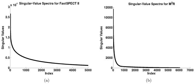
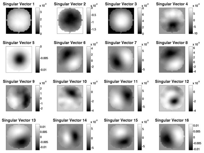
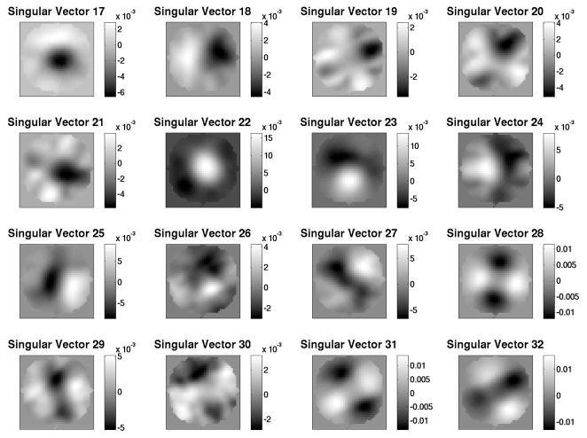
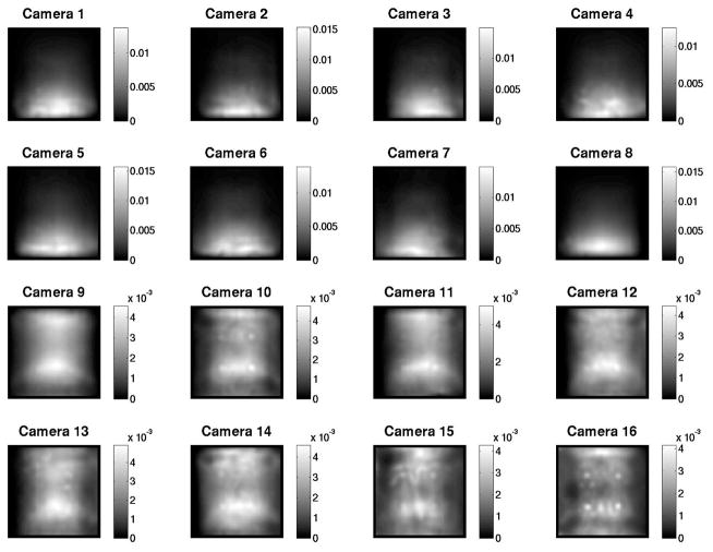
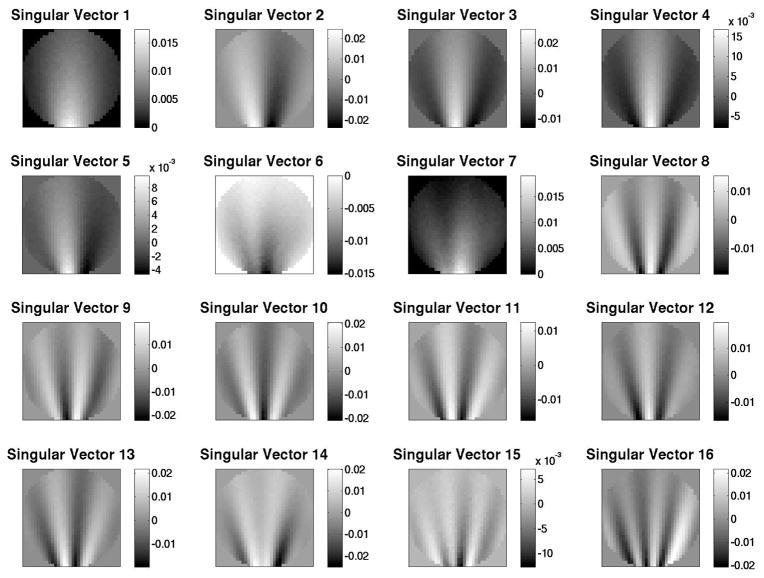
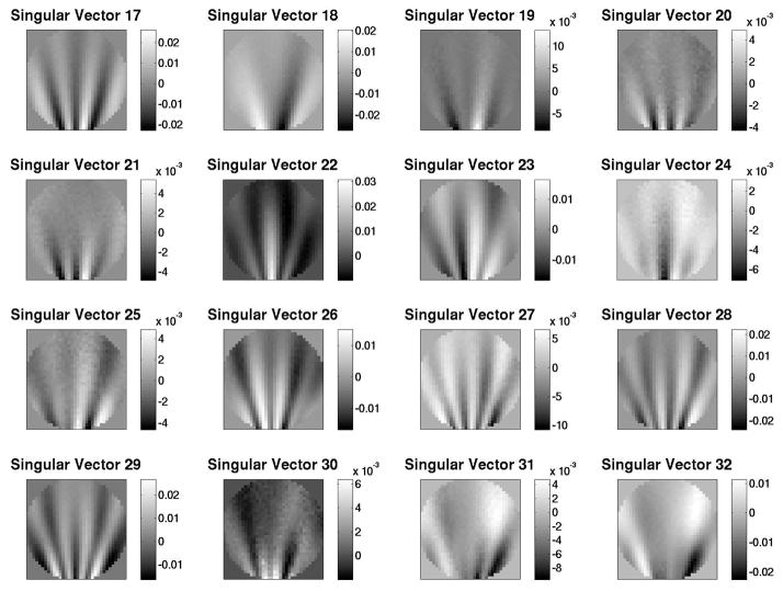
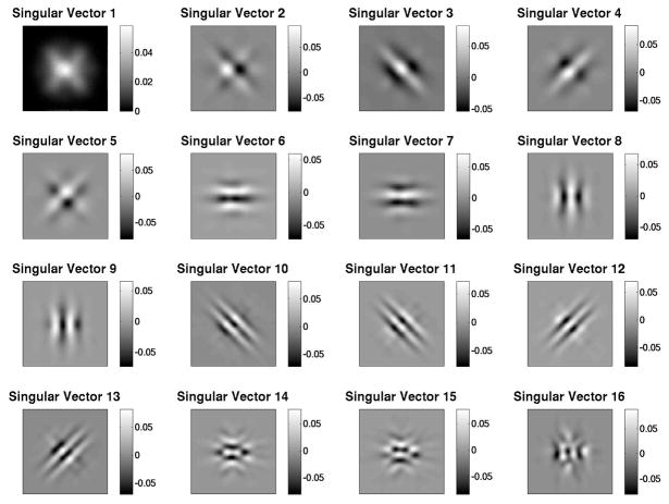
The computed singular-value spectra for the FastSPECT II and M3R systems are shown in Fig. 1. For the FastSPECT II system we were able to compute 5000 singular values. Our attempts to process additional singular values were unsuccessful due to inadequate memory within our current resources. We are pursuing the use of high powered computing resources at the University of Arizona to increase the memory available to the algorithm. For the M3R system we computed 6082 singular values. This is the maximum number of singular values that can be determined for this system using our current implementation of the Lanczos method. Beyond this point the algorithm is numerically unstable. Numerical stability of the Lanczos method is discussed in Cullum.1 Singular vector data for the FastSPECT II system is presented in Fig. 2, Fig. 3, and Fig. 4. Singular vector data for the M3R system is presented in Fig. 5, Fig. 6, and Fig. 7. Object space singular vectors are shown as 2D slices of the 3D vectors.
Figure 1.
(a) The largest 5000 singular values for the FastSPECT II system. Our current computing resources were unable to allocate enough memory to compute more than this number of singular values for the FastSPECT II system. However, this number of elements may be sufficient for system assessment tasks since the spectrum exhibits a significant drop in magnitude within the 5000 computed singular values. (b) The largest 6082 singular values for the M3R system. The Lanczos method is subject to numerical instability for small singular values. The 6082 computed values represents the number of eigenvalues that could be computed for this system before arriving at this stability threshold.
Figure 2.
A 2D slice through object space singular vectors 1–16 for the FastSPECT II system.
Figure 3.
2D slice through object space singular vectors 17–32 for the FastSPECT II system.
Figure 4.
Image space singular vector 1 for the FastSPECT II system.
Figure 5.
2D slice through object space singular vectors 1–16 for the M3R system.
Figure 6.
2D slice through object space singular vectors 17–32 for the M3R system.
Figure 7.
Image space singular vectors 1–16 for the M3R system.
The data we have computed using the Lanczos method is consistent with the characteristics of singular values and singular vectors expected by SVD theory. The singular-value spectra for each system exhibits a sharp drop in magnitude for higher indexed vectors. For the largest singular value the structure of the associated singular vector is of low frequency. For smaller singular values the associated singular vectors contain higher ordered oscillatory structures indicating an increase in high frequency content. The orthogonality of the singular vectors is difficult to observe from the slice images presented in this paper but was verified by checking that the inner product of sample vectors within a space was zero.
An application of this data with respect to the characterization of imaging systems is that it can be used to calculate the measurement space and null space of the system for a given object.4 For the discrete to discrete model given by Eqn. 3, a vector f in object space can be expanded in terms of basis vectors ui into its measurement component and null component as
| (20) |
Assuming we have computed data to the point that the singular-value spectra has effectively reached zero coefficients αi for i = 1, 2, …, R can be determined. The measurement component can then be calculated by the first summation term of Eqn. 20 which in turn gives the null space of the system as
| (21) |
The null space of is used to understand the component of an object that cannot be imaged by a particular system.8 A common example of a null function is a spatial frequency that is beyond the cutoff frequency of a linear shift invariant system. As part of this study we have processed null space calculations for several objects for the M3R system using the computed singular vectors and are currently working to validate these vectors by comparing them to the null space components calculated using an iterative algorithm9 that has been used in previous CGRI studies.
Acknowledgments
The authors acknowledge Dr. Doug Rohde and his implementation of the SVDLIBC package which was used extensively for this project. This work was supported under NIH/NIBIB grants R01-EB002146 and P41 EB002035.
References
- 1.Cullum J, Willoughby R. Theory. I. Birkhauser; Boston: 1985. Lanczos Algorithms for Large Symmetric Eigenvalue Computations. [Google Scholar]
- 2.Sehmi N. Large Order Structural Eigenanalysis Techniques: Algorithms for Finite Element Systems. Ellis Horwood; 1989. [Google Scholar]
- 3.Berry M, Do T, OBrien G, Krishna V, Varadhan S. SVDPACKC: Version 1.0: User’s Guide. University of Tennessee, Computer Science Dept; 1993. [Google Scholar]
- 4.Barrett H, Myers K. Foundations of Image Science. John Wiley and Sons; 2004. [Google Scholar]
- 5.Chen Y. PhD thesis. University of Arizona; 2006. System calibration and image reconstruction for a new small-animal SPECT system. [Google Scholar]
- 6.Hesterman J. PhD thesis. University of Arizona; 2007. The multi-module multi-resolution SPECT system: a tool for variable-pinhole small-animal imaging. [Google Scholar]
- 7.Hesterman J, Kupinski M, Furenlid L, Wilson D, Barrett H. The multi-module, multi-resolution system (M3R): A novel small-animal SPECT system. Medical Physics. 2007;34:987–993. doi: 10.1118/1.2432071. [DOI] [PMC free article] [PubMed] [Google Scholar]
- 8.Barrett H, Aarsvold J, Roney T. Null functions and eigenfunctions: tools for the analysis of imaging systems. Prog Clin Biol Res. 1991;363:211–26. [PubMed] [Google Scholar]
- 9.Wilson D, Barrett H. Decomposition of images and objects into measurement and null components. Optics Express. 1998;2(6):254–260. doi: 10.1364/oe.2.000254. [DOI] [PubMed] [Google Scholar]


