Abstract
Concentric tube robots are a subset of continuum robots constructed by combining pre-curved elastic tubes. As the tubes are rotated and translated with respect to each other, their curvatures interact elastically, enabling control of the robot's tip configuration as well as the curvature along its length. This technology is projected to be useful in many types of minimally invasive medical procedures. Because these robots are flexible by design, they deflect considerably when applying forces to the external environment. Thus, in contrast to rigid-link robots, their kinematic and static force models are coupled. This paper derives a multi-tube quasistatic model that relates tube rotations and translations together with externally applied loads to robot shape and tip configuration. The model can be applied in robot design, procedure planning as well as control. For validation, the multi-tube model is compared experimentally to a computationally-efficient single-tube approximate model.
I. Introduction
The goal of minimally invasive surgery (MIS) is to interact with tissue deep inside the body while minimizing collateral damage to surrounding tissues. In contrast to open surgery in which access is gained by making large incisions, MIS involves entering the body through small incisions and, whenever possible, following natural passages through the tissues to reach the surgical site. Manual and robotic catheters are successful examples of an MIS instrument technology which have been specifically developed for procedures inside the vasculature [1],[2].
There are many medical procedures that could benefit from an instrument technology with the ability of catheters to follow complex curves, but which require much more tip stiffness than that of a catheter. These include structural repairs inside the heart and tissue removal inside the brain.
Few instrument technologies exist, however, that possess significant tip stiffness in combination with the ability to assume 3D curves inside the body. Conventional surgical robots, for example, possess high stiffness, but consist of straight shafts comparable to traditional laparoscopic tools [3]. To address this shortcoming, bending snake-like robotic extensions have been proposed and constructed for mounting at the tip of the straight shaft [4]. A novel, alternate approach consists of a robotic sheath that can be extended along a 3D curve [5].
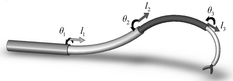
Concentric tube robots offer a good compromise between shape control and stiffness. As illustrated by the example of Fig. 1, they can be constructed to possess a full six degrees of freedom at their tip while also enabling control of curvature along their length. Furthermore, they can be constructed with diameters comparable to catheters and lengths sufficient to reach anywhere inside the body while achieving a tip stiffness several orders of magnitude greater than that of a catheter. The lumen of the innermost tube can house additional tubes and wires for controlling articulated tip-mounted tools.
Fig. 1.
Concentric tube robot comprised of four telescoping sections that can be rotated and translated with respect to each other.
Concentric tube robots, like steerable catheters [1],[2] and snake-like multi-backbone devices [4], are continuum robots. In comparison to traditional robot arms, this class of robots lacks distinct links and joints. Continuum robots possess the shape of a smooth curve whose curvature can be controlled by adjusting the internal deformation of mechanically coupled elastic components of the body.
Consequently, the kinematic modeling of continuum robots cannot be formulated solely in terms of constrained motion between rigid bodies, but must also incorporate deformation modeling of the elastic components [1],[4],[6]-[9]. For concentric tube robots, the deformation is that of the individual tubes [6]-[9].
Owing to both the complexity of the modeling problem as well as to the desire to derive numerically efficient models for real-time control, a succession of kinematic models of increasing complexity have been proposed over the last few years as described in [8]-[9]. While providing significantly improved accuracy over earlier models, these new models are considerably more complex. They consist of second-order differential equations with split boundary conditions. To achieve computational efficiency, these equations can be pre-computed over the workspace and stored either in the form of a functional approximation or as a lookup table [8]. The inverse kinematic problem can be solved efficiently by root finding on the approximate forward solution [8]. Alternately, an inverse functional approximation or lookup table can be similarly constructed.
While the kinematic models of [8]-[9] assume that there is no external loading applied to the robot (see [10] for an exception), applications in minimally invasive surgery can be expected to involve loads applied along the robot's length as well as at its tip. Unlike robots whose links can be approximated as rigid bodies, however, the kinematic and static force models of continuum robots cannot be decoupled.
Thus, when considering the important case of external loads applied to the robot, the model for implementing position, force or impedance control takes the form of a coupled 3D beam-bending problem in which the kinematic input variables (tube rotations and displacements at the proximal end) enter the problem as a subset of the boundary conditions. The remaining boundary conditions are comprised of point forces and torques applied to the distal ends of the tubes. Contact along the robot's length (e.g., with tissue) generates additional distributed and point loads.
In contrast to the models of [8]-[9], the inclusion of external loading significantly increases the number of state variables that must be integrated along the lengths of the tubes. As an alternative to this full-order model, a computationally-efficient approximate model that can be applied to all types of continuum robots has been proposed and successfully implemented for concentric-tube robot stiffness control [11]-[13]. In this approach, the continuum robot is modeled as a single Cosserat rod with properties along its length corresponding to the composite stiffnesses and initial curvatures of the unloaded robot.
The contributions of this paper are the derivation of a multi-tube quasistatic model as well as a computational and experimental comparison of the multi-tube model with the single-tube model of [11]-[13]. The paper is arranged as follows. Section II derives the multi-tube externally-loaded model. Section III presents the simplified single-tube approximate model. Section IV provides an experimental comparison of the models. Conclusions are presented in Section V.
II. Quasistatic Multi-Tube Model
The multi-tube model derived here can be interpreted as an extension of the unloaded model presented in [8]. It includes bending and torsion for an arbitrary number of tubes whose curvature and stiffness can vary with arc length. Effects that are neglected include shear of the cross section, axial elongation, nonlinear constitutive behavior and friction between the tubes. Note that these effects are neglected, but are not necessarily all negligible.
In the remainder of the paper, subscript indices i = 1, 2,…, n are used to refer to individual tubes with tube 1 being outermost and tube n being innermost. Arc length, s, is measured such that s = 0 at the proximal end of the tubes. The total length of each tube is designated by Li.
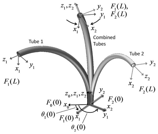
As illustrated in Fig. 2, for two tubes, material coordinate frames for each cross section can be defined as a function of arc length s along tube i by defining a single frame at the proximal end, Fi (0) , such that its z axis is tangent to the tube's centerline. Under the unrestrictive assumption that the tubes do not possess initial material torsion, the frame, Fi (s), is obtained by sliding Fi (0) along the tube centerline without rotation about its z axis (i.e., a Bishop frame [14]). As the tubes move, bend and twist, these material frames act as body frames tracking the displacements of their cross sections. It is also useful to define a reference frame, F0 (s) , which displaces with the cross sections, but does not rotate about its z axis under tube torsion.
Fig. 2.
Tube coordinate frames are denoted Fi (s). The relative z-axis twist angle between tube frame F0(s) and frame Fi (s) is θi (s).
As the ith tube's coordinate frame Fi (s) slides down its centerline, it experiences a body-frame angular rate of change per unit arc length given by
| (1) |
in which (uix , uiy) are the components of curvature due to bending and uiz is the curvature component due to torsion. A circumflex on a curvature component is used to designate the initial pre-curvature of a tube.
The kinematic input variables consist of the rotation and translation of each tube about and along the common centerline of the combined tubes. The rotation angle, θi (s), is defined as the z -axis rotation angle from frame F0 (s) to frame Fi (s). The translation variable, li, is defined as the arc length distance from frame F0 (0) to the initially coincident frame Fi (0) . In the rest of the paper, all vector quantities associated with tube i , e.g., ui (s) , are written with respect to frame Fi (s). Vectors associated with the robot, e.g., net bending moment, are written with respect to frame F0 (s) .
As shown in the figure, insertion of one tube inside the other causes each to bend and twist along their length. The application of externally applied wrenches generates additional bending and twisting of the tubes.
A. Derivation of Multi-tube Model
The quasistatic model including external loading can be derived by combining three equations – a constitutive model relating bending moments to changes in curvature of individual tubes, the equilibrium of bending moments and shear forces on the cross section of the assembled tubes, and a compatibility equation relating the individual curvatures of the assembled tubes. Additional equations are needed to compute the net shear force and bending moment on the robot as a function of arc length.
The constitutive model and compatibility equations are independent of the external loading and so are identical to those of the unloaded kinematic model presented in [8]. The equilibrium equation of [8], however, must be modified to include the net bending moment arising from external loads. Furthermore, to compute net bending moment, new differential equations must be introduced to compute both it and net shear force. Each is described below.
(1) Constitutive Model
When a tube with initial curvature ûi (s) is deformed to a different curvature ui (s) , a bending moment is generated. Assuming linear elastic behavior, the bending moment vector mi (s) at any point s along tube i is given by
| (2) |
Given the coordinate frame convention described above, all vectors are expressed with respect to frame Fi (s) , and Ki is the frame-invariant stiffness tensor given by
| (3) |
in which Ei is the modulus of elasticity, Ii is the area moment of inertia, Ji is the polar moment of inertia and Gi is the shear modulus of tube i.
(2) Compatibility of Deformations
Assuming that the clearance between each pair of adjacent tubes is just sufficient to enable relative motion, all tubes must conform to the same final x-y (bending) curvature. Each tube is free, however, to twist independently about its z axis. The z component of curvature, ui (s)|z , equates to the rate of change of twist angle with respect to arc length, θ̇i,
| (4) |
The resulting bending curvatures can be equated when written in the same frame. Expressing tube curvatures in terms of the robot frame curvature, θ0, results in
| (5) |
in which Rz(θi)∈SO(3) is a rotation about the z axiz by angle θiez = [0,0,1]T.
(3) Equilibrium of Bending Moments
On each cross section, the bending moments in each tube must sum to the robot's net bending moment, m0(s), generated by the external loading.
| (6) |
As in (5), Rz(θi) is used to transform tube bending moments from frame Fi(s) to frame F0(s).
Combining (2) and (6) expresses net bending moment in terms of tube curvatures,
| (7) |
Solving (5) and (7) for u0(s) provides an expression for robot curvature in terms of initial tube curvatures and net bending moment,
| (8) |
Since frame F0(s) by definition does not rotate about its z axis, u0|z = 0, and so this equation can written in two parts as
| (9) |
| (10) |
Equations (5) and (9) enable the computation of the x and y curvatures of all tubes using
| (11) |
An expression is also needed to compute the z curvature of all tubes, uiz = θ̇i, i = 1, …, n. Such an expression can be obtained from the equilibrium equation of the special Cosserat rod model [15]-[17]. Setting time dependent terms to zero, the body-frame equilibrium equations for a curved rod undergoing distributed loading of τ ∈ ℝ3 torque per unit length and f ∈ ℝ3 force per unit length can be applied to each tube
| (12) |
Derivatives are with respect to arc length along the rod, s, and mi,ni ∈ ℝ3 are the bending moment and shear force vectors acting on the tube's cross section. Here, and in the remainder of the paper, the square brackets on the vectors ui and vi denote the skew-symmetric form
| 13 |
Consistent with the previous notation, ui(s),vi(s) ∈ ℝ3 are the angular and linear strain rates per unit arc length, respectively, experienced by the tube's cross section. Thus, as described previously, ui(s) has the units of curvature. Similarly, the x and y components of vi(s) are the shear strain components of the cross section while the z component is viz = 1 + εiz in which εiz is the longitudinal strain. Given the assumptions of negligible shear and longitudinal strain,
| (14) |
It can be helpful to note that ui(s) and vi(s) are analogous to body-frame angular and linear velocities if time is substituted for arc length. Wrenches applied at either end of the rod enter the equations as boundary conditions.
Since tube interaction is limited to distributed forces, τi(s) = 0 in (12) and, for each tube, it reduces to
| (15) |
To eliminate moments from these equations, we can use the constitutive model for moments (2) and its derivative to arrive at
| (16) |
Equations (4) and (16) are a set of second order differential equations for the tubes' twist angles, θi, that must be integrated using the algebraic equations (9) and (11). These equations are identical to those describing the unloaded kinematic model except that (9) now includes the net bending moment on the tubes, m0(s) [8].
(4) Net Bending Moment and Shear Force
While (11) provides the z component of m0(s), it is the x and y components that are needed for (9). To compute net bending moment as a function of arc length, the equilibrium special Cosserat model (12) can be applied again, but this time to the collection of tubes.
| (17) |
Since net bending moment on the robot's cross section evolves together with net shear force, n0(s), both must be simultaneously integrated. Here τ0(s) and f0(s) are the externally applied distributed torque and force per unit length of the robot as shown in Fig. 3.
Fig. 3.
External loading on robot consists of distributed forces, f0(s), and distributed moments, τ0(s), as well as concentrated forces, n0(L), and concentrated moments, m0(L).
Robot curvature, u0(s), is defined by (8) and since (14) applies to all tubes comprising the robot,
| (18) |
Equations (4),(9)-(11),(16)-(18) form a set of equations in the state variables {θi(s),θ̇j,(s)m0(s),n0(s)}, i = 1, …n; j = 2, …,n. Observe that θ̇1,(s) = u1z(s) can be computed algebraically from (10).
The boundary conditions for the state variables are split between the proximal and distal ends of the robot.
| (19) |
The x and y components of ui(L) can be computed from (9) and (11). While (10) evaluated at s = L provides an expression for the weighted sum of uiz(L), i = 1,…,n, it is insufficient to solve for the individual values of uiz(L). This can be resolved by assuming that the total external twisting moment is applied to a single tube, say tube j. The resulting values for uiz(L) are given by
| (20) |
Physically, this situation corresponds to tube j extending slightly beyond the other tubes so that it comprises the tip of the robot.
There is, in fact, no reason that the tubes must be of the same length. The equations above apply to any telescoping arrangement of tubes in which the stiffness and pre-curvature of each tube can be an arbitrary function of arc length. This includes discontinuities in both stiffness and pre-curvature. Consequently, there is no need to subdivide the domain during integration over a telescoping arrangement of tubes. Distal to the physical end of each tube, its stiffness and curvature can be defined as zero.
B. Numerical Solution of Multi-tube Model
When solving the multi-tube equations given by (4),(9)-(11), (16)-(18) together with boundary conditions defined by (19) and (20), three issues must be considered. First, the boundary conditions are split between the ends of the tubes. Second, integration of (v0(s) ∈ ℝ3, u0(s) ∈ so(3)) to obtain the robot coordinate frame, F0 (s), must be performed such that it evolves on SE(3) . Thirdly, while the external loading in these equations is expressed in the body coordinate frame, it is often convenient to express external loads with respect to a different frame. Each of these issues is addressed in the paragraphs below.
(1) Split Boundary Conditions
The problem of split boundary conditions is one that has been addressed with the unloaded kinematic equations. In fact, the unloaded equations can be recovered by setting the external loading to zero [8].
| (21) |
While such equations can be solved by a variety of standard means, one approach is to pose the forward kinematics as a root finding problem in which guesses of θi(L) are used to integrate from s = L → 0 until the desire values of θi (0) are obtained.
(2) Integration on SE(3)
Integrating the unloaded kinematics required integrating tube curvatures with respect to arc length. Analogous to integrating body frame twist velocity, numerical integration of ui and vi must preserve the group structure of SE(3). A variety of numerical integration methods are available for this purpose [16],[18],[19].
(3) External-Load Coordinate Frame
It is often desirable to express the loading in different coordinates than the body frame coordinates of (19) and (20). In this case, however, the boundary condition is a function of the shape of the robot. For example, suppose it is desired to produce a tip wrench that is specified with respect to the base frame of the robot, F0 (0) . Then the body-frame tip wrench, written with respect to frame F0 ( L) is related to the desired world frame tip wrench, written with respect to frame F0 (0) , by
| (22) |
in which R0L and p0L describe the orientation and position of frame F0 (L) with respect to frame F0 (0) . In this case, the equations must be solved iteratively with respect to both tip wrench and actuator positions.
III. Approximate Single-Tube Model
In contrast to the model presented above, references [11]-[13] propose an approach in which the load-deflected shape of a continuum robot is computed as the sequence of two transformations. The first employs an unloaded kinematic model to compute the robot configuration. This configuration together with the external loading are the inputs to a second transformation that computes the deflected shape by modeling the robot as a single rod with its stiffness given by the composite stiffness of the robot's elements. While approximate since it ignores internal displacements arising from loading, its solution takes the form of an initial value problem and so can be computed efficiently.
The equations to be solved are a subset of those for the multi-tube model and consist of (2), (17), (18) which are repeated here for clarity.
| (23) |
| (24) |
| (25) |
As before, m0(s) and n0(s) are the net bending moment and shear force on the robot as functions of arc length. Robot curvature, u0(s), described in coordinate frame F0(s), is algebraically related to m0(s). The composite robot stiffness, K0(s), is defined as the effective bending and torsional stiffness of the robot cross section as a function of arc length.
The initial robot curvature, û0(s), is obtained as the output of the unloaded forward kinematic model. The boundary conditions for these equations are given by a subset of (19) consisting of the applied tip force and bending moment.
| (26) |
Since the boundary conditions are all defined at the distal end of the robot, they can be solved as an initial value problem by integrating from the tip back to the base.
The solution is, however, subject to the conditions described in sections II.B.2 and II.B.3 above. Namely, the equations must be integrated on SE(3) . Furthermore, if the tip loading is not defined with respect to the body frame then the initial value problem must be solved iteratively to account for the rotation of the body tip frame in response to deflection. In real-time use, the number of iterations can be minimized by using the tip frame rotation from the preceding time step as the initial guess.
A. Comparison with Multi-tube Model
The computational costs of the models can be assessed by considering the total number of state variables and the locations of the boundary conditions as summarized in Table 1. While not included in the table, it is also necessary for both models to simultaneously integrate (v0(s),u0(s)) to obtain the coordinate frame F0(s).
Table 1.
State variables used by Multi-tube and Single-tube models.
| State variable | Boundary Coandition |
Multi-tube Model |
Single-tube Model |
|---|---|---|---|
| θi(s), i = 1, …, n | Base | n | - |
| θ̇j(s), j = 2, …, n | Tip | n−1 | - |
| m0 (s) ∈ ℝ3 | Tip | 3 | 3 |
| n0(s) ∈ ℝ3 | Tip | 3 | 3 |
|
| |||
| Total number | 2n+5 | 6 | |
Exclusive of F0(s), the total number of state variables is 2n+5 for the multi-tube model. Since each tube of a robot contributes two degrees of freedom corresponding to its rotation and translation, it requires three tubes to produce a robot with six degrees of freedom. For such a robot, solution of the multi-tube model involves integrating eleven state variables with respect to arc length using split boundary conditions. The single-tube model possesses six states regardless of the number of tubes and all boundary conditions are at the distal end.
Since computation of the unloaded kinematic model involves those variables that are omitted from the single-tube model, it is tempting to argue that sequential solution of the unloaded kinematic model followed by the single-tube model of loading deflection is of the same computational complexity as the multi-tube model. This is not the case, however, for two reasons. First, solving two sets of decoupled equations is simpler than solving a single coupled set. Secondly, it has been shown that the unloaded kinematic model can be accurately represented by an algebraic functional representation [8] and so can be implemented without any on-line integration.
IV. Experimental Model Evaluation
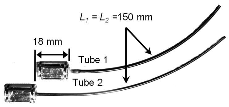
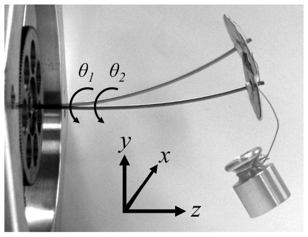
To compare the models, experiments were performed to measure the deflection and twisting of a pair of NiTi tubes experiencing a tip force. The tubes are shown disassembled in Fig. 4. Each tube is glued into a collar as shown and mounted in the motor drive system of Fig. 5. Motor positioning accuracy is better than 0.1 degrees. As shown in Fig. 4, the outer tube includes a straight section at its proximal end to accommodate the 18 mm length of the inner tube's collar. To account for the twisting that will occur in the straight section, the motor angles are given in terms of the tube angles by
| (27) |
As the tubes are rotated from the aligned configuration shown in Fig. 4 and Fig. 5, their combined curvature varies from its maximum value (1/241 mm−1) to approximately zero when θ2(0)–θ1(0) = π.
Fig. 4.
Individual tubes comprising variable curvature tube pair.
Fig. 5.
Tube pair mounted in drive system. Double exposure shows tubes in unloaded and gravity-loaded configurations. Tip-mounted disk for measuring relative tube twist is also shown. Orientation of coordinate frame F0(0) is labeled.
Tube parameters are shown in Table 2. Equation (9) requires values for both the bending and torsional stiffnesses of the tubes as defined by (3). The quantities Ii, Ji can be calculated from the tube cross sections and values of Ei,Gi are available in the literature. The combination of tube diameter tolerances and variation in moduli arising during shape setting, however, leads to large variations in estimated stiffness.
Table 2.
Properties of Tubes Used in Experiments.
| Tube 1 | Tube 2 | |
|---|---|---|
| OD (mm) | 2.77±0.01 | 2.41±0.01 |
| ID (mm) | 2.55±0.01 | 1.97±0.01 |
| kx,y=EI (N·m2) - Calculated | 3.34×10⁻² | 3.67×10⁻² |
| kx,y=EI (N·m2) - Measured | 2.85×10⁻² | 3.75×10⁻² |
| Length (mm) | 150 | 150 |
| Pre-curvature ûy (mm−1) (ûx = ûz = 0) | 1/233 | 1/248 |
To avoid this issue, stiffnesses were estimated as follows. First, the stiffness ratio kx1,y1/kx2,y2 was computed from (9) by measuring the pre-curvature of each tube and the combined curvature for θ2(0) − θ1(0) = π. Second, the combined tubes with θ2(0) = θ1(0) were deflected in the plane of the curvature using a 200 g mass and the resultant displacement measured. Treating the pair as a single tube, (17) was used to iteratively estimate the combined stiffness (k1x,1y + k2x,2y) from the measured deflection. The individual stiffnesses were calculated from these two measurements. The ratio of bending to torsional stiffness was calculated using the standard value of Poisson's ratio, ν = 0.3 , for NiTi.
| (28) |
A. Experimental Procedure
Gravity loading was used to generate tip forces on the robot in the three coordinate directions shown in Fig. 5. Since the forces are applied in the world frame (via gravity), the resultant tip frame forces generally contain x, y and z components. Note that gravity deflection due to robot mass (< 0.3mm) was within the measurement error of the camera system and was therefore neglected.
For each tip load, the tubes were rotated with respect to each other through a full rotation. For every 10 degrees of relative rotation, tip position and tip rotation angle were recorded. In this way, measurements were recorded as the curvature of the robot varied from its maximum to its minimum (approximately straight) and back to its maximum. This was performed for both directions of relative rotation.
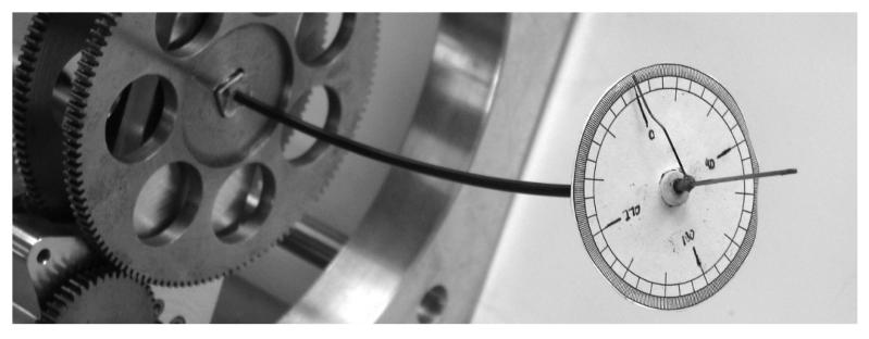
Measurements of tip position were made using a stereo camera measurement system (Vision Appliance, Dalsa, Inc.) that determines points in world space to within ±0.5 mm and relative points to within ±0.2 mm. To measure tip rotation angle, a circular graduated disk was attached over the last 2 mm of the outer tube. As shown in Fig. 6, a pointer attached to a tapered dowel was inserted into the end of the inner tube and zeroed for the configuration in which the curvature of the tubes is aligned. The error in measuring tip angle was estimated to be ±2 degrees. Care was taken to ensure that the disk and pointer did not interfere with attachment of the mass.
Fig. 6.
Disk and pointer for measuring relative angle at tip.
B. Experimental Results
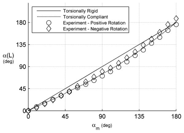
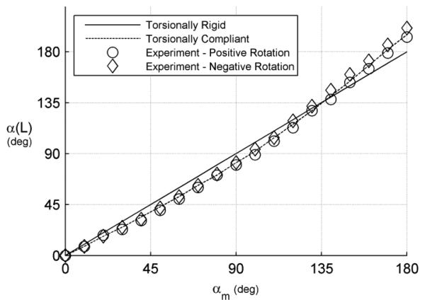
The multi-tube model predicts that the individual tubes will twist in response to external loading. This effect was observed experimentally and can be seen by comparing Fig. 7 and Fig. 8. In the unloaded case of Fig. 7, torsional twisting of the tubes causes the tip twist angle to lag twist at the motor for this range of relative angles. This occurs since smaller twist angles correspond to a lower energy state. The application of a tip force in the –y direction, however, acts to straighten the tube pair and so produce a corresponding increase in twist angle at the tip for nonzero twist angles at the motors. The maximum difference between the experimental data of Fig. 7 and Fig. 8 is about 15 degrees at αm = 180 deg. Note that it is this relative twisting in response to load that the single-tube model neglects.
Fig. 7.
Relative tube twist angle, α = θ2 − θ1, at the tip, α(L), versus the motor, αm, for the case of no external loading using the torsionally-rigid model of [6] and the torsionally-compliant model of [8].
Fig. 8.
Relative tube twist angle, α = θ2 − θ 1, at the tip, α(L) , versus the motor, αm, for a 200 gram gravity load in the -y direction of Fig. 5 (in the plane of robot curvature).
Model error is summarized in Table 3 for tip gravity loads of 0, 100 and 200 grams applied in the three coordinate directions of Fig. 5. Since deflection of the robot due to its own weight is negligible, model error for zero tip load does not vary with coordinate direction.
Table 3.
Tip Position Error for Multi-tube (m) and Single-tube (s) Models. Gravity load direction with respect to robot curvature is specified using the coordinate directions of Fig. 5.
| Load direction, mass (grams) |
Mean (mm) |
Std Dev (mm) |
Max (mm) |
|||
|---|---|---|---|---|---|---|
| m | s | m | s | m | s | |
| {x,y,z}, 0 | 1.91 | 1.91 | 0.29 | 0.29 | 2.60 | 2.60 |
| −y, 100 | 1.95 | 2.19 | 0.42 | 0.54 | 3.26 | 3.26 |
| −y, 200 | 2.01 | 3.13 | 0.93 | 1.72 | 3.98 | 6.54 |
| −x, 100 | 4.26 | 4.44 | 2.29 | 2.23 | 6.55 | 6.59 |
| −x, 200 | 5.73 | 6.26 | 2.72 | 2.46 | 8.54 | 8.79 |
| z, 100 | 2.53 | 2.54 | 0.71 | 0.75 | 3.86 | 4.05 |
| z, 200 | 2.50 | 2.51 | 0.64 | 0.69 | 3.53 | 3.73 |
| {x,y,z}, {100,200} |
2.98 | 3.28 | 1.97 | 2.05 | 8.54 | 8.79 |
In comparison to the unloaded model, tip loading increases the mean tip error by more than 50% from 1.91 mm to about 2.98 mm. Standard deviation increases by a factor of 6.8 from 0.29 mm to 1.97 mm, and maximum tip position error increases by a factor of 3.3 from 2.6 mm to 8.54 mm.
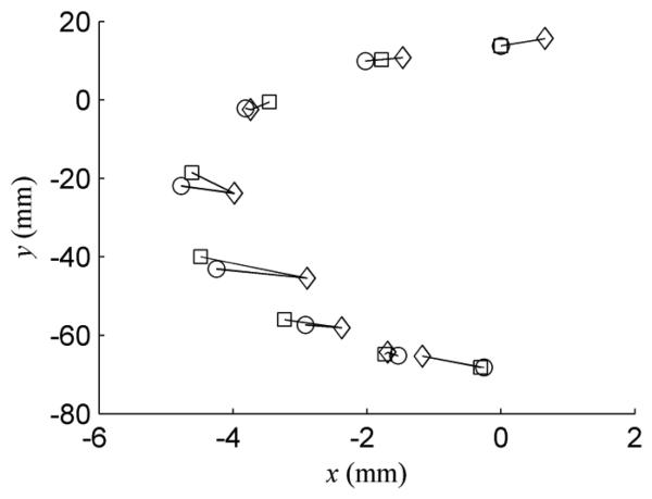
Perhaps most surprising, the mean error for the single-tube model is only 0.3 mm larger than that of the multi-tube model. The differences between the standard deviation and maximum errors for the two models are even smaller. Furthermore, the directionality of tip position error was determined to be similar for the two models by plotting the data sets in three dimensional space. As an example, Fig. 9 provides a planar view of a subset of the data corresponding to a load of 200 g applied in the negative y direction.
Fig. 9.
Tip position in the x-y plane for robot loaded with 200 g in the −y direction. Data points correspond to unloaded robot curvature varying from the configuration of Fig. 5 to zero and then to the configuration in which robot is curved downward. Diamonds are measured positions; circles are the multi-tube model predictions; squares are the single-tube model predictions. Associated positions are connected by lines.
V. Conclusions
Understanding and predicting the deformation of concentric tube robots in response to environmental contact is important for design, planning and real-time control. The work presented here provides a multi-tube quasistatic model incorporating concentrated as well as distributed forces and torques. A comparison with a simplified single-tube model is also included. Experiments show that the uncalibrated multi-tube model has a mean error of less than 4mm for the tubes presented. It is important to note that much of the error can be attributed to specific subsets of configurations, suggesting that the model omits some important phenomena. Surprisingly, the single-tube model showed similar tip error and may be more appropriate for real-time control applications.
Acknowledgments
This work was supported by the National Institutes of Health under grants R01HL073647 and R01HL087797.
Contributor Information
Jesse Lock, Biomedical Engineering, Boston University, Boston, MA 02215 USA (lockj@bu.edu)..
Genevieve Laing, Mechanical Engineering, Boston University, Boston, MA 02215 USA (glaing@bu.edu)..
Mohsen Mahvash, Harvard Medical School, Boston MA 02115 USA (mohsenmahvash@gmail.com)..
Pierre E. Dupont, Cardiovascular Surgery, Children's Hospital Boston, Harvard Medical School, Boston MA 02115 USA (Pierre.Dupont@childrens.harvard.edu)..
REFERENCES
- 1.Camarillo D, Milne C, Carlson C, Zinn M, Salisbury JK. Mechanics Modeling of Tendon-Driven Continuum Manipulators. IEEE Trans. Robotics. 2008 Dec.24(6):1262–1273. [Google Scholar]
- 2.Meeker DC, Maslen EH, Ritter RC, Creighton FM. Optimal realization of arbitrary forces in a magnetic stereotaxis system. IEEE Trans. on Magnetics. 1996 Mar;32(2):320–328. [Google Scholar]
- 3.Madhanir A, Niemeyer G, Salisbury JK., Jr. The Black Falcon: A Teleoperated Surgical Instrument for Minimally Invasive Surgery; IEEE/RSJ Int. Conference on Intelligent Robots and Systems, Victoria, B.C.; Canada. 1998. pp. 936–944. [Google Scholar]
- 4.Xu K, Simaan N. An Investigation of the Intrinsic Force Sensing Capabilities of Continuum Robots. IEEE Trans. Robotics. 2008;24(3):576–587. [Google Scholar]
- 5.Degani A, Choset H, Wolf A, Zenati M. Highly Articulated Robotic Probe for Minimally Invasive Surgery; IEEE Int. Conf. on Robotics & Automation; Orlando. 2006. pp. 4167–4172. [DOI] [PMC free article] [PubMed] [Google Scholar]
- 6.Sears P, Dupont P. A Steerable Needle Technology Using Curved Concentric Tubes; IEEE/RSJ Int. Conference on Intelligent Robots and Systems; Beijing. 2006. pp. 2850–2856. [Google Scholar]
- 7.Webster RJ, III, Romano JM, Cowan NJ. Mechanics of Precurved-Tube Continuum Robots. IEEE Trans Robotics. 2009;25(1):67–78. [Google Scholar]
- 8.Dupont P, Lock J, Itkowitz B, Butler E. Design and Control of Concentric Tube Robots. IEEE Trans Robotics. 2010;26(2):209–225. doi: 10.1109/TRO.2009.2035740. [DOI] [PMC free article] [PubMed] [Google Scholar]
- 9.Rucker D, Webster R, III, Chirikjian G, Cowan N. Equilibrium Conformations of Concentric-tube Continuum Robots. Int J Robotics Research. 2010 doi: 10.1177/0278364910367543. [DOI] [PMC free article] [PubMed] [Google Scholar]
- 10.Rucker D, Jones B, Webster R., III A Model for Concentric Tube Continuum Robots Under Applied Wrenches; IEEE Int. Conf. on Robotics & Automation; Anchorage, AK. 2010. pp. 1047–1052. [Google Scholar]
- 11.Mahvash M, Dupont P. Bilateral Teleoperation of Flexible Surgical Robots. Workshop Proc, New Vistas and Challenges in Telerobotics; IEEE 2008 Int Conf Robotics & Automation.2008. pp. 58–64. [Google Scholar]
- 12.Mahvash M, Dupont P. Stiffness Control of a Continuum Manipulator in Contact with a Soft Environment; IEEE/RSJ Int Conf Intelligent Robots and Systems; Taipei, Taiwan. 2010. [DOI] [PMC free article] [PubMed] [Google Scholar]
- 13.Mahvash M, Dupont P. Stiffness Control of Continuum Surgical Manipulators. IEEE Trans. Robotics. 2010 doi: 10.1109/TRO.2011.2105410. in press. [DOI] [PMC free article] [PubMed] [Google Scholar]
- 14.Bishop RL. There is More than One Way to Frame a Curve. The American Mathematical Monthly. 1975 March;82(3):246–251. [Google Scholar]
- 15.Antman SS. Nonlinear problems of elasticity. Springer Verlag; New York: 1995. [Google Scholar]
- 16.Pai D. Strands: Interactive Simulation of Thin Solids Using Cosserat Models. Eurographics'02. 1990;21(3):347–352. [Google Scholar]
- 17.Trivedi D, Lofti A, Rahn C. Geometrically Exact Models for Soft Robotic Manipulators. IEEE Trans. Robotics. 2008;24(4):773–780. [Google Scholar]
- 18.Crouch PE, Grossman R. Numerical integration of ordinary differential equations on manifolds. Journal of Nonlinear Science. 1993;3(1):1–33. [Google Scholar]
- 19.Park J, Chung W-K. Geometric integration on Euclidean group with application to articulated multibody systems. IEEE Trans. Robotics. 2005;21(5):850–863. [Google Scholar]


