Abstract
An important challenge facing the design of turbodynamic ventricular assist devices (VADs) intended for long-term support is the optimization of the flow path geometry to maximize hydraulic performance while minimizing shear-stress-induced hemolysis and thrombosis. For unshrouded centrifugal, mixed-flow and axial-flow blood pumps, the complex flow patterns within the blade tip clearance between the lengthwise upper surface of the rotating impeller blades and the stationary pump housing have a dramatic effect on both the hydrodynamic performance and the blood damage production. Detailed computational fluid dynamics (CFD) analyses were performed in this study to investigate such flow behavior in blade tip clearance region for a centrifugal blood pump representing a scaled-up version of a prototype pediatric VAD. Nominal flow conditions were analyzed at a flow rate of 2.5 L/min and rotor speed of 3000 rpm with three blade tip clearances of 50, 100, and 200 μm. CFD simulations predicted a decrease in the averaged tip leakage flow rate and an increase in pump head and axial thrust with decreasing blade tip clearances from 200 to 50 μm. The predicted hemolysis, however, exhibited a unimodal relationship, having a minimum at 100 μm compared to 50 μm and 200 μm. Experimental data corroborate these predictions. Detailed flow patterns observed in this study revealed interesting fluid dynamic features associated with the blade tip clearances, such as the generation and dissipation of tip leakage vortex and its interaction with the primary flow in the blade-blade passages. Quantitative calculations suggested the existence of an optimal blade tip clearance by which hydraulic efficiency can be maximized and hemolysis minimized.
Keywords: Blade tip clearance, Hemolysis, Shear stress history, Left ventricular assist device, Computational fluid dynamics, Optimization
An important challenge facing the design of the turbodynamic ventricular assist devices (VADs) intended for long-term support is the optimization of the flow geometry to maximize hydraulic performance while minimizing shear-stress-induced hemolysis and thrombosis. The large variety of pumps developed for this application typically target similar nominal requirements for flow and pressure head. Yet their configuration varies dramatically. Guidelines for shrouded and unshrouded industrial pumps have evolved from extensive experimental and analytical investigations (1–3). Some of these hydrodynamic characteristics can be adapted for preliminary selection of blood pumps; however, these data do not consider the most important factors for pumping blood, namely thrombogenicity and blood cell trauma. In addition, the relatively small size of pumps used for implanted applications entails fluid dynamics and associated loss mechanisms that differ from their larger counterparts. Therefore, the design of blood pumps must rely on modern design approaches to optimize the flow path. Computational fluid dynamics (CFD) studies have been used to facilitate this process, and minimize the use of expensive and painstaking trial-and-error experimentation (4,5).
Both types of shrouded and unshrouded (semi-open) impellers have been widely used in centrifugal and mixed-flow blood pumps (6–9). For a shrouded impeller, the fluid within the clearance space between the rotating front shroud and the stationary housing demonstrates a complex three-dimensional structure (see Fig. 1a). Although the fluid adjacent to the rotating front shroud tends to accelerate by centrifugal force to flow radially outwards toward the outlet of the impeller, the high downstream pressure (e.g., within the volute) forces the fluid retrograde toward the pump inlet. The retrograde leakage flow may further mix with incident flow in the inlet to induce pre-rotation, particularly at the off-design flow conditions. The same retrograde flow pattern can also occur at the back shroud (5), where the combination of disk friction loss and strong vortical flow may potentially induce hemolysis and thrombosis.
FIG. 1.
(a) Meridional sectional view of shrouded (closed) centrifugal pump illustrating typical retrograde flow in the clearance between the shroud and housing. (b) Meridional section of unshrouded (semi-open) impeller. (c) Typical tip leakage flow for unshrouded impeller from pressure-side to suction-side of blade, illustrating the formation of tip leakage vortex.
These limitations motivate the use of unshrouded impellers. However, the removal of the front shroud introduces a new problem due to the blade tip leakage flow from the pressure-side to the suction-side of the blade, through the clearance between the rotating blade tip and the stationary housing (see Fig. 1b,c). The resulting tip leakage flow is a very complex phenomenon. Because of the relative counter-rotation between the housing and blades, some amount of the leakage flow tends to “adhere” to the housing without contribution to the pump pressure rise. The leakage flow can also generate a jet leakage vortex that interacts and mixes with the primary flow, causing hydraulic loss and possibly inducing blood trauma.
An experimental study of the complex flow phenomena with an unshrouded blood pump was recently reported by Antaki et al. (6) in which the flow of blood cells was microscopically visualized within the blade tip region at various tip gap dimensions. The current study was undertaken to extend and complement the latter study by detailed CFD analysis of this experimental device, having a 46 mm diameter impeller. In addition to elucidating the fluid dynamics, these simulations also intended to provide quantitative predictions of the associated blood damage.
MATERIALS AND METHODS
Pump geometrical model and computational details
The pump geometry of this study was motivated by the first-generation version of a miniature pediatric VAD (P-VAD) developed by our group (5) (see Fig. 2). This pump, having a 6-bladed unshrouded impeller with a diameter of 12.5 mm, was designed using our CFD-based inverse design optimization method (5,10) to deliver 0.3–1.5 L/min at 100 mm Hg. The impeller blades were based on high-performance hydrofoil modified from National Advisory Committee for Aeronautics (NACA) 2412 by thickening and rounding the trailing edge. Both the inlet and outlet volutes were likewise described parametrically with B-spline curves and surfaces (11). To visualize the micro fluid dynamics of the red blood cells within the blade tip clearance and to facilitate the arrangement of experimental instruments, a scaled-up experimental model having a 46 mm diameter impeller was designed according to geometric and dynamic similitude (12,13) using the following head and flow coefficients:
| (1) |
| (2) |
yielding a nominal flow rate of 2.5 L/min and rotor speed of 3000 rpm.
FIG. 2.
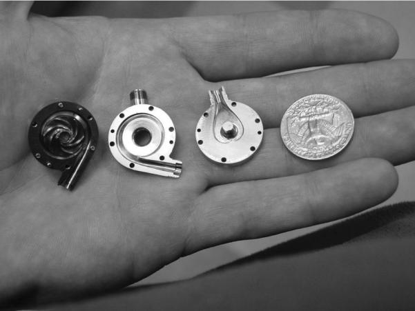
Centrifugal pediatric VAD prototype including the 12.5 mm impeller, outlet, and inlet volutes.
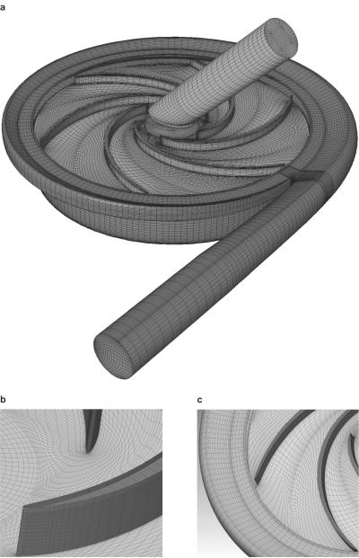
The computational meshes for the full flow path of the experimental version were generated with our internally-developed automatic mesh generation tool based on the elliptic method (5). They consisted of multiblock structured grids with high-quality hexahedral cells clustered toward the wall surfaces with boundary orthogonality (see Fig. 3). To provide optical access to the impeller, the symmetric semi-scroll inlet volute of the prototype was replaced by a simplified straight pipe, which was meshed using a “butterfly” type grid with orthogonal boundaries. Particular attention was paid to the meshes surrounding the blades. A clustered C-grid was prescribed to capture the steep velocity gradient around the leading edge and the surface of the blades and to facilitate the coupling between the rotating impeller and the stationary volute (see Fig. 3b,c). The grid within the back clearance region, modified to account for a shaft drive of the experimental pump was generated using six nodes across the gap. Because of the particular interest in the flow within the blade tip clearance, eight nodes were distributed across the gap, clustered near the walls for each of the clearance sizes as illustrated in Fig. 3b. Approximately 600 000 cells were used for the entire pump model, with grid sensitivity studies performed to ensure accuracy within a reasonable central processing unit (CPU) time.
FIG. 3.
CFD meshes for scaled-up experimental pump with 46 mm diameter impeller. (a) Entire flow domain, (b) detail of C-grid around the leading edge of blades and the grid at the blade tip region (top of blade tip), and (c) detail of C-grid near the trailing edge of blades and the partial grid of volute and hub regions.
Numerical simulation of blood flow was accomplished using a commercial CFD solver (CFX, ANSYS, Inc., Canonsburg, PA, USA), which incorporates an element-based finite volume method suitable for both unstructured and structured meshes. The representative Reynolds number for this problem was 98 700 based on the impeller outlet diameter and the pump tip speed (Re = ρu2D2/μ). The shear stress transport (SST) model (14), typically prescribed for turbulence of low Reynolds number, was selected over the more common κ – ε transport model for its robustness and superior accuracy in problems involving rotation and high curvature (10,15). A linear (Newtonian) constitutive model with a dynamic viscosity of 0.0035 Pa-s and a density of 1040 kg/m3 was assumed for blood. This was justified by the relatively high shear rates in the pump, as compared to the range in which shear thinning is expressed (approximately <100 s−1). Interfaces between the rotational and stationary components were coupled using the frozen rotor method with multiple frames of reference (14). The small-scale blade tip clearance region was integrated with the impeller domain in the rotational frame with a counter-rotating wall boundary condition imposed in the stationary housing. A uniform velocity distribution was implemented as the inlet boundary condition with the specified turbulent intensity, while a pressure boundary condition was assumed for the outlet boundary. Simulations were performed at the above mentioned nominal flow conditions for each of three different blade tip gaps: 200, 100, and 50 μm.
Shear-induced blood trauma (hemolysis) was estimated by computing the damage accumulation along 6000 particle pathlines using a Lagrangian particle tracking technique (16) and applying a power-law empirical damage model as suggested by Giersiepen (17) and Heuser (18):
| (3) |
where Di represents the blood damage index for each particle, C, α and β denote constants originally specified by Giersiepen as C = 3.62 × 10⁻⁵, a= 2.416, and β= 0.785; and later corrected by Heuser as C = 1.8 × 10⁻⁶, α= 1.991, and β= 0.765. Our experience shows that both models yielded very close value of hemolysis in blood pumps. We acknowledged the limitations of applying these coefficients, derived from uniform-shear experiments in Couette-type flow, to the current problem. However, we assumed that this would not affect the comparative evaluation of multiple gaps within the same pump. To account for the highly time-variant shear history of blood cells through the pump, the cumulative damage was estimated by the method as originally proposed by Palmgren and Miner (19,20) and then extended to blood pumps by Bludszuweit (21) based on the assumption of linear accumulation of shear at different loading levels:
| (4) |
where n is the number of total particles released in the pump inlet, and Di is calculated according to Eq. 3. Because of the three-dimensional character of the shear field, the Von Mises stress provided a representative scalar norm for incorporation into Eq. 4, as proposed by Bludszuweit (21):
| (5) |
where the components of the stress tensor were computed from the summation of the components of the viscous and Reynolds stress tensor (16).
RESULTS
CFD simulations for the experimental blood pump at the nominal flow condition (flow rate = 2.5 L/min, impeller speed = 3000 rpm) predicted a reduction of pump head with increasing tip gap from 50 to 100 μm of approximately 10% and from 50 to 200 μm of approximately 25% (see Fig. 4). This trend is quite similar to the experimental data from the same pump reported previously (6), although the CFD simulation systematically over-predicted the pump head for all the three tip gaps considered. The net torque on the impeller was computed based on the simulated pressure field and wall shear stress, thereby allowing estimation of the hydraulic efficiency as the ratio of hydrodynamic power output to shaft work:
| (6) |
where Q is flow rate, H is the pump head, T is the torque acting on the axis of the pump impeller, and w is impeller rotational speed. As the blade tip clearance was reduced from 200 to 100 μm, the pump efficiency increased from 21.8 to 23.9% (see Table 1). However, as the blade tip clearance decreased further from 100 to 50 μm, the efficiency remained relatively constant at 23.75%. The predicted axial thrust acting on the entire impeller that included the combined effect of both front and back clearances is also provided in Table 1. With the decrease of the blade tip clearance, the axial thrust acting on the rotor increased. This trend also agrees well with the experimental data in industrial pumps (12,13).
FIG. 4.
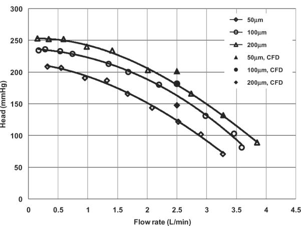
Comparison of the computed pressure head versus measured H-Q curves for three different blade tip clearances of the scaled-up model at 3000 rpm.
TABLE 1.
CFD predicted efficiency and axial thrust for three different blade tip clearances (flow rate = 2.5 L/min, and pump speed = 3000 rpm)
| Blade tip clearance (μm) | Efficiency (%) | Thrust (N) |
|---|---|---|
| 50 | 23.75 | 11.5 |
| 100 | 23.90 | 10.5 |
| 200 | 21.80 | 9.4 |
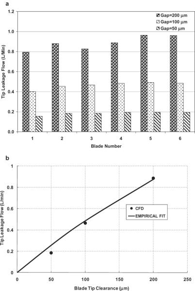
The volumetric loss due to tip leakage was computed by integrating the normal component of velocity within the effective area of the blade tip gap by post-processing. Figure 5a displays the blade tip leakage flow rate for the three different blade tip gaps at the nominal flow condition. The tip leakage flow rate over each of the six blades monotonically decreased with the tip clearance, but showed slight circumferential nonuniformity from blade to blade, due to the asymmetry of the flow field caused by the volute and cutwater. This nonuniformity was emphasized with the increase of the blade tip clearance. For example, the maximal blade-blade variation for the 200 μm gap simulation approached 0.2 L/min, which is about one fifth of the total tip leakage flow. The averaged tip leakage flow rate over six blades versus tip clearances is shown in Fig. 5b, along with the following empirical regression:
| (7) |
where g is gravity; H is the pump head; ϕq is a constant that is dependent on the pump geometry and is taken as 0.37 for the current pump model; and A is the effective leakage flow area calculated as the product of blade tip gap and the camber-line length of the blade.
FIG. 5.
(a) Tip leakage flow through each of six blade tip gaps for different tip clearances (flow rate = 2.5 L/min, and pump speed = 3000 rpm); blades numbered clockwise, starting with blade closest to cutwater. (b) The mean leakage flow through six blade tips versus blade tip clearances.
Local features of tip leakage flow
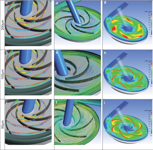
Figure 6a–c shows the relative velocity vectors projected onto the four different radial cross sections at the nominal flow condition for the three blade tip clearances. Due to the pressure difference between the pressure and suction sides of the blades and the relative motion between the housing and the blade, the blood was throttled across the blade tip gap to form a jet leakage flow. The relative amount of leakage was found to increase with increasing radius as would be expected due to increased blade loading. As the leakage flow re-entered the blade-to-blade channel, it mixed with the primary flow to generate a secondary leakage vortex. This vortex was closer to the suction side for the larger blade tip clearance. It is also noted that near the outlet of the impeller, the vortices disappeared at all the three selected tip clearances. Such a flow structure may promote deposition on the suction face of the blade.
FIG. 6.
Velocity field illustrating tip leakage for three clearances studied. Left column: relative velocity vectors projected onto four radial sections of r = 7.5, 10, 15, and 20 mm, colored according to velocity magnitude. Middle column: particle pathlines. Right column: Scalar shear stress distribution on cut-plane through mean height of blade tip clearance. (Rotational direction is clockwise.)
The velocity fields were also visualized using Lagrangian particle tracking by uniformly released particles from the tip clearances above the six blades. It was revealed that the tip leakage vortex was shed adjacent to the suction side of the blades at the tip clearance of 200 μm (see Fig. 6d). With the decrease of the blade tip clearance, the vortex was entrained more strongly by the relative motion of the housing and propelled by the pressure gradient toward the pressure side of the blades, where it formed a smaller vortex tube (see Fig. 6e,f).
Evaluation of hemolysis
Figure 6g–i displays the scalar (Von Mises) shear stress distribution on the cut-plane through the mean height of the blade tip clearance. The higher shear stress was observed to be concentrated in the region over the blade tips with a predominant zone near the blade trailing edges at a clearance gap of 200 μm (see Fig. 6g). With the decrease of the tip clearance, the shear stress became greater and more concentrated with the higher predominant shear stress zone spreading toward the leading edge (see Fig. 6h,i). The maximal shear stresses on the cut-plane through the mid-gap are shown in Fig. 7, along with the following empirical regression:
| (8) |
where δ is the blade tip clearance gap in μm and τmax in Pa.
FIG. 7.
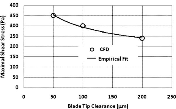
Maximal shear stress on the middle plane of blade tip clearances.
Blood damage was evaluated by Lagrangian particle-tracking on the basis of the assumption of a linear accumulation as described above. Figure 8 shows a representative, decimated distribution in which only tens of the 6000 particle traces are displayed for clarity. The computed overall hemolysis through the pump model based on 6000 particles by Eq. 4 is provided in Fig. 9 for three different blade tip clearances. At the gap of 200 μmm, the predicted overall blood damage index, DHb, was 0.0253. As the clearance gap reduced to 100 μm, the predicted hemolysis index dropped dramatically to 0.0046. With the further decrease of the blade tip clearance to 50 μm, however, the hemolysis index rose to 0.0418.
FIG. 8.
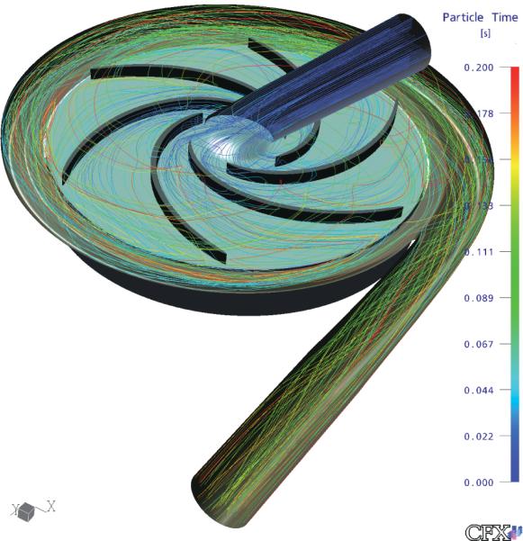
Pathlines from tens of representative particles (out of a total of 6000 particles) released to compute the shear history and estimate hemolysis.
FIG. 9.
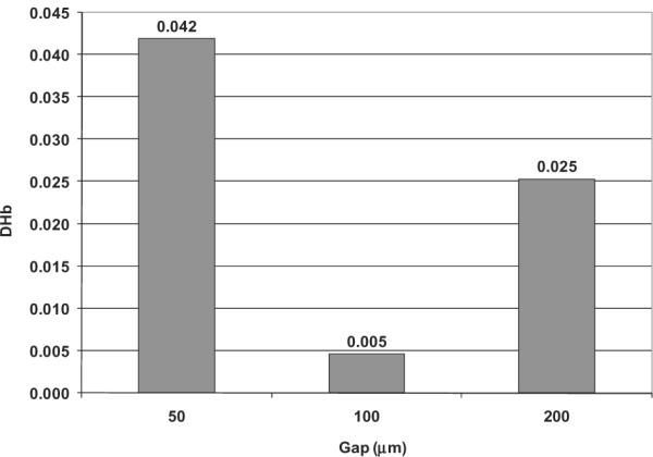
Mean estimated blood damage through the pump model for three different blade tip clearances (based on 6000 particles).
Further analysis of the regional contributions to overall blood damage indicated that the inlet pipe was negligible compared to that in the impeller and volute regions (see Fig. 10). The calculated distribution of hemolysis was almost the same for both the blade tip gaps of 50 and 200 μm: approximately 70% of the total blood damage in the impeller region, and about 30% of the total in the volute region. The intermediate tip gap of 100 μm, however, exhibited less hemolysis in the impeller region (approximately 46% of the total) compared to the volute (54% of the total).
Fig. 10.

Proportion of total blood damage contributed by different pump components for three blade tip clearances.
DISCUSSION
The specification of blade tip gap is arguably the single most important determinant of cell trauma in a turbodynamic pump. It is therefore surprising that the fluid dynamics within blade tip clearances of unshrouded impellers have not been studied extensively. Developers wishing to avoid excessive shear may employ relatively large blade tip clearances. However, this inevitably entails a compromise between hemocompatibility and performance, because the blade tip is also highly responsible for hydraulic efficiency. The CFD simulations performed in this study attempted to gain a better understanding of this tradeoff.
Large clearances will contribute to both volumetric and head losses in the impeller. Some studies have shown that the blade tip clearance may account for over one third of the hydraulic efficiency of a pump (22). The relatively small size of impellers used for ventricular assist devices amplifies the effect of blade tip clearance on performance: tip clearances of just a few thousandths of an inch may represent 10% of the overall blade height (5).
In the current studies, the volumetric tip leakage rate was computed by integrating the normal component of velocity within the clearance region along the full camber-line length of the blade. An important distinction should be made between this phenomenon and “regurgitant flow” which is essentially the integral of the retrograde component of meridional velocity—typically applied to the clearance between shroud and casing of a shrouded impeller. Although there may exist a very slight retrograde component of meridional velocity within the blade tip region of an unshrouded impeller, it is far predominated by the circumferential component and thus impossible to form a retrograde flow. Therefore, CFD analysis must be cautioned from misinterpreting the blade tip leakage flow as retrograde leakage flow, as has been erroneously done previously (23,24).
CFD simulations reported here revealed that increasing blade tip clearance caused a drop in pump head, as observed experimentally (6). This is partly because the leakage flow effectively “adheres” to the housing, hence without contributing to the dynamic head. The tip leakage was found to be unevenly distributed among the six blades, and this variation increased with larger gap clearance. This trend may be attributed to the stronger interaction of flow between the impeller and volute region as clearance gap became larger. It could also be partly due to discretization errors caused by the decrease of mesh density. In spite of this asymmetry, a relatively simple empirical relationship was found to characterize the net volumetric loss in terms of the pump head and area of the leakage path. This provides a convenient means to estimate the volumetric loss, which is otherwise very difficult to measure directly.
Unlike industrial pumps, in which the efficiency usually varies almost linearly with the blade tip clearance (12,13), the predicted hydraulic efficiency for this blood pump was only slightly affected by clearance gap with a maximum near the gap of 100 mm. This paradoxical result implies that energy gained due to decreased volumetric leakage was counteracted by increased viscous losses, which requires higher torque, as the gap approaches a certain small critical value. This is not surprising if we consider that flow within a turbodynamic blood pump usually has a lower Reynolds number than that of an industrial pump. Therefore, the viscous effects predominate the inertial effects, particularly within the blade tip gap region. As the gap decreases—in the present case less than 100 μm—the viscous effects become increasingly consequential. It is reasonable to assume that the relationship between the efficiency and the blade tip gap is not linear; and therefore there must exist an optimal blade tip clearance at a certain small threshold for which efficiency is maximized. It should be pointed out that in spite of experimental validation for efficiency by CFD providers, we have found that errors still can arise associated with turbulence model, mesh density and quality, etc. We have made our great efforts to mitigate these errors by using a low-Reynolds SST turbulence model and using custom-developed multiblock structured meshes with boundary orthogonality and clustering near the surfaces for the entire geometry model. In particular, special attention has been made to mesh the blade tip clearance region with the grids clustering to both the housing and blade surfaces. However, simulations of additional blade tip clearances, both within and outside the range studied would be beneficial to more definitively demonstrate the existence and location of the optimum.
Calculation of blood trauma revealed an interesting unimodal relationship between hemolysis and blade tip clearances: the intermediate gap dimension (100 μm) provided lesser blood trauma than either 50 or 200 μm. Similar trends have been observed previously in both experimental and numerical studies of hemolysis in blood-lubricated bearings with clearances in the range of 80–60 μm (25). These results are also corroborated by James et al. (26) who reported minimal levels of hemolysis in a ventricular assist pump having a blood lubricated bearing with clearance gaps in the range of 75–215 μm. These results may appear counterintuitive in consideration of the damage function of Eq. 4. This paradox may be explained by considering the cumulative release of plasma free hemoglobin, which is the product of the volumetric flow rate through the gap and the intensity of localized damage generation. Because the blade tip leakage flow rate varies with the tip clearance almost linearly (see Fig. 5b), it is reasonable to assume that the exposure time through the gap does not change with the clearance gaps. As the size of the gap is decreased from 200 to 100 μm, the leakage flow rate through the gap is reduced over 50% (see Fig. 5b), excluding a commensurate proportion of cells exposed to this gap zone. Although the shear stress increases, the slope is less sharp (see Fig. 7), thus leading to the considerable decrease of blood damage. This may reflect a possible screening effect, as described by Fåhraeus (27) in small tubes, and observed by Antaki et al. (6) within the impeller blades of the experimental counterpart of this numerical study. However, as the blade tip clearance gap is further decreased to 50 μm, the shear stress over the gap increases sharply (see Fig. 7, and Eq. 8), predominating the effect of the decreased leakage flow rate (because the blood damage index is proportional to 2.416 power of the shear stress), thus leading to an overall increase of the blood damage through the pump.
The preceding discussion signals an important consideration when attempting to simulate blood damage in a turbodynamic pump by Lagrangian particle tracking. Because blood is usually treated as a single continuum, a very large number of particles required to span the computational domain and adequately represent the “hot spots” within the flow path. Previous studies employing only tens, or at the most hundreds of particles to compute hemolysis, are inadequate to produce a statistically representative distribution of shear history. In this study, a total of 6000 particles were released at the inlet of the pump model for each case to avoid pathlines-dependence of hemolysis computations. Future studies are likely to be elaborated by considering two-phase constitutive models for blood.
Further inspection of the flow field within the blade-blade region revealed the presence of vortex shedding from the tip region resulting in variable secondary flow patterns. Such a flow structure may suggest potential risk of deposition on the suction face of the blade. Decreasing the blade tip clearance caused the vortex to migrate farther downstream, as far as the pressure side of the subsequent blade, essentially “dragged” backwards by the stationary housing and propelled forward by the pressure gradient. As the resulting vortex tube inevitably mixed with the primary flow in the blade-blade channel, this contributed additional hydrodynamic losses.
Analysis of hemolysis throughout the blood flow path revealed that shear history within the volute caused a comparable level of hemolysis production as within the impeller region. In fact, for the case of 100 μm clearance gap, the hemolysis generation in the volute exceeded that of the impeller. This is not altogether surprising considering the well known fact that the volute of a centrifugal pump accounts for a major component of the total hydraulic losses (13,22). This emphasizes the importance of improving volute design for both performance and hemocompatibility—analogous to the impeller blade clearance.
CONCLUSIONS
Detailed flow patterns presented in this study revealed some interesting fluid dynamic features associated with the blade tip clearances, such as the generation and dissipation of tip leakage vortex and its interaction with the primary flow in blade-blade regions. CFD simulations of a centrifugal VAD with 46 mm impeller predicted a decrease in the averaged tip leakage and an increase in pressure head and axial thrust with decreasing blade tip clearances from 200 to 50 μm. The predicted hemolysis, however, exhibited an interesting unimodal relationship, having a minimum at 100 μm compared to 50 μm and 200 μm. Future attempts to optimize the design of turbodynamic blood pumps with unshrouded impellers are therefore advised to place particular emphasis on the tradeoffs associated with blade tip leakage. And additional investigations into the mechanisms responsible for blood damage and energy loss caused by the blade tip are warranted.
Acknowledgment
This research was supported in part by contract N01-HV-48192 (Pediatric Circula-tory Support) from NHLBI/NIH.
REFERENCES
- 1.Goto A. Study of internal flows in a mixed-flow pump impeller at various tip clearances using three-dimensional viscous flow computations. ASME J Turbomach. 1992;114:373–82. [Google Scholar]
- 2.Engeda A, Rautenberg M. Comparison of the relative effect of tip clearance on centrifugal impellers. ASME J Turbomach. 1987;109:545–9. [Google Scholar]
- 3.Hirsch C, Kang S, Pointel GA. Numerically supported investigation of the 3-d flow in centrifugal impellers, Part II: secondary flow structure. ASME Paper. 1996:96-GT–152. [Google Scholar]
- 4.Antaki JF, Ghattas O, Burgreen GW, He B. Computational flow optimization of rotary blood pump components. Artif Organs. 1995;19:608–15. doi: 10.1111/j.1525-1594.1995.tb02389.x. [DOI] [PubMed] [Google Scholar]
- 5.Wu J, Antaki JF, Wagner W, Snyder T, Paden B, Borovetz H. Elimination of adverse leakage flow in a miniature pediatric centrifugal blood pump by computational fluid dynamics-based design optimization. ASAIO J. 2005;51:636–43. doi: 10.1097/01.mat.0000178966.79876.3d. [DOI] [PubMed] [Google Scholar]
- 6.Antaki JF, Diao CG, Shu FJ, Wu JC, Zhao R, Kameneva MV. Microhaemodynamics within the blade tip clearance of a centrifugal turbodynamic blood pump. JEIM. 2008;222:573–81. doi: 10.1243/09544119JEIM352. [DOI] [PubMed] [Google Scholar]
- 7.Ichikawa S, Nosé Y. Centrifugal blood pumps for various clinical needs. Artif Organs. 2002;26:916–8. doi: 10.1046/j.1525-1594.2002.07113.x. [DOI] [PubMed] [Google Scholar]
- 8.Bearnson G, Jacobs G, Kirk J, Khanwilkar P, Nelson K, Long J. HeartQuest ventricular assist device magnetically levitated centrifugal blood pump. Artif Organs. 2006;30:339–46. doi: 10.1111/j.1525-1594.2006.00223.x. [DOI] [PubMed] [Google Scholar]
- 9.Chan WK, Wong YW, Ding Y, Chua LP, Yu SCM. Numerical investigation of the effect of blade geometry on blood trauma in a centrifugal blood pump. Artif Organs. 2002;26:785–93. doi: 10.1046/j.1525-1594.2002.06954.x. [DOI] [PubMed] [Google Scholar]
- 10.Wu J, Shimmei K, Tani K, Niikura K, Sato J. CFD-based design optimization for hydro turbines. ASME J Fluids Eng. 2007;129:159–68. [Google Scholar]
- 11.Rogers DF. An Introduction to NURBS: With Historical Perspective. Morgan Kaufmann; San Francisco, CA: 2001. [Google Scholar]
- 12.Japikse D, Marscher W, Furst R. Centrifugal Pump Design and Performance. Concepts ETI, Inc.; 1997. [Google Scholar]
- 13.Stepanoff AJ. Centrifugal and Axial Flow Pumps: Theory, Design and Application. John Wiley & Sons; New York: 1966. pp. 69–75. [Google Scholar]
- 14.CFX ANSYS . User's Guide. 2006. [Google Scholar]
- 15.Mitoh A, Yano T, Sekine K, et al. Computational fluid dynamics analysis of an intra-cardiac axial flow pump. Artif Organs. 2003;27:34–40. doi: 10.1046/j.1525-1594.2003.07190.x. [DOI] [PubMed] [Google Scholar]
- 16.Wu J, Antaki JF, Snyder TA, Wagner WR, Borovetz HS, Paden BE. Design optimization of blood shearing instrument by computational fluid dynamics. Artif Organs. 2005;29:482–9. doi: 10.1111/j.1525-1594.2005.29082.x. [DOI] [PubMed] [Google Scholar]
- 17.Giersiepen M, Wurzinger LJ, Optiz R, Reul H. Estimation of shear stress-related blood damage in heart valve prostheses—in vitro comparison of 25 aortic valves. Int J Artif Organs. 1990;13:300–6. [PubMed] [Google Scholar]
- 18.Heuser G, Optiz RA. Couette viscometer for short time shearing of blood. Biorheology. 1980;17:17–24. doi: 10.3233/bir-1980-171-205. [DOI] [PubMed] [Google Scholar]
- 19.Yeleswarapu K, Antaki JF, Kameneva M, Rajagopal K. A mathematical model for shear-induced hemolysis. Artif Organs. 1995;19:576–82. doi: 10.1111/j.1525-1594.1995.tb02384.x. [DOI] [PubMed] [Google Scholar]
- 20.Yokobori T. An Interdisciplinary Approach to Fracture and Strength of Solids. Wolters-Noordhoff Scientific Publications Ltd; Groningen: 1968. [Google Scholar]
- 21.Bludszuweit C. Model for a general mechanical blood damage prediction. Artif Organs. 1995;19:583–9. doi: 10.1111/j.1525-1594.1995.tb02385.x. [DOI] [PubMed] [Google Scholar]
- 22.Dey D, Camci C. Development of tip clearance flow downstream of a rotor blade with coolant injection from a tip trench. 8th International Symposium on Transport Phenomena and Dynamics of Rotating Machinery; March 2000.pp. 572–9. [Google Scholar]
- 23.Anderson J, Wood H, Allaire P, Bearnson G, Khanwilkar P. Computational flow study of the continuous flow ventricular assist device, prototype number 3 blood pump. Artif Organs. 2000;24:377–85. doi: 10.1046/j.1525-1594.2000.06442.x. [DOI] [PubMed] [Google Scholar]
- 24.Song X, Wood H, Olson D. Computational fluid dynamics (CFD) study of the 4th generation prototype of a continuous flow ventricular assist device (VAD) ASME J Biomech Eng. 2004;126:180–7. doi: 10.1115/1.1688776. [DOI] [PubMed] [Google Scholar]
- 25.Kataoka H, Takatani S. Measurement and simulation of hemolysis in a hydrodynamic bearing of a centrifugal blood pump. ASAIO. 2006;52:7A. [Google Scholar]
- 26.James NL, Wilkinson C, Lingard N, Meer AL, Woodard J. Evaluation of hemolysis in the VentrAssist implantable rotary blood pump. Artif Organs. 2003;27:108–13. doi: 10.1046/j.1525-1594.2003.07188.x. [DOI] [PubMed] [Google Scholar]
- 27.Fåhraeus R. Suspension stability of the blood. Physiol Rev. 1929;9:241–74. [Google Scholar]


