Abstract
This study investigates the effect of surface cross-linked heparin on vascular endothelial growth factor (VEGF)-mediated angiogenesis in porous polycaprolactone (PCL) scaffolds in vivo. We tested the hypothesis that VEGF delivered by scaffolds coated with a sub-micron thick layer of immobilized heparin would accelerate angiogenesis. The bioactivity of retained VEGF was confirmed by its phosphorylation of VEGF receptor-2. After 7 and 14 days of subcutaneous implantation in mice, the heparin-PCL scaffolds loaded with VEGF displayed significantly higher infiltration of blood vessels which traversed the entire scaffold thickness (2 mm). The stability and function of the newly formed vessels were confirmed by smooth muscle cell coverage and vessel perfusability, respectively. The contribution of individual components was assessed by varying the VEGF dose and heparin thickness. Prolonging the cross-linking reaction on PCL scaffolds resulted in higher heparin content, thicker heparin layer, and higher VEGF retention. While a dose-dependent angiogenic response was observed with VEGF, higher amount of cross-linked heparin did not translate into additional improvement in angiogenesis for a given dose of VEGF. The synergism of immobilized heparin and VEGF in stimulating angiogenesis was observed in vivo.
Keywords: Scaffold, Polycaprolactone, Surface modification, Heparin, Cross-linking, Angiogenesis
1. Introduction
A significant challenge in tissue engineering is poor engraftment and non-uniform proliferation of cells within the tissue engineering scaffold. Due to limited diffusion of metabolites and hypoxia, cells seeded in the inner core of the scaffold tend to perish, and cellular proliferation becomes confined to a few hundred micrometers in the periphery. Rapid formation of blood vessels is critical to alleviate the hypoxia-induced cell death within tissue-engineered scaffolds. Natural angiogenesis, however, is a relatively slow process that involves synchronized participation of cells and growth factors. Although various strategies have been devised to deliver pro-angiogenic growth factors, such as encapsulation in microsphere [1], entrapment in hydrogel [2, 3], covalent [6,9,10] or, electrostatic binding [4], the problem of inadequate blood vessels within scaffolds remains at large. Even with these interventions, the newly formed vessels are typically restricted to the outer periphery scaffold during the first few weeks [1-5]. This time-lag between the onset of hypoxia and the establishment of new, functional vessels, contributes to the pro-apoptotic environment in the inner core of tissue engineering scaffolds.
While improvement in angiogenesis has been reported with the delivery of multiple growth factors [1-4, 6], gene targeting and growth factor antagonist experiments suggest that vascular endothelial growth factor (VEGF) may be sufficient to induce angiogenesis [7, 8]. Recent findings in developmental biology provide compelling evidence that heparin sulfate proteoglycans in the extracellular matrix provides optimal balance between diffusion and retention of VEGF [11-13]. Heparin presents specific motifs of negatively charged sulfate groups that can bind growth factors and limit their diffusion. Heparin also has a relatively long half-life of days, in contrast to minutes for VEGF, and preserves the bioactivity of bound proteins against thermal and enzymatic degradation [14]. Heparin-based scaffolds have been used for delivery of VEGF [15-17] and other heparin-binding growth factors to enhance angiogenesis, bone, cartilage, liver and neuronal regeneration [18-22].
We sought to grow blood vessels more rapidly as well as more uniformly within the entire thickness of scaffold using heparin-coated scaffolds to deliver VEGF. The growth of blood vessels as a function of distance from the scaffold-host interface is documented at 7 and 14 days after implantation.
2. Materials and methods
2.1 Fabrication of polycaprolactone (PCL) scaffold
Porous PCL (Mw = 110,000) (Lactel Absorbable Polymers, Pelham, AL) scaffolds were prepared by solvent casting and particulate leaching technique. Briefly, PCL (10% w/w) was dissolved in a mixed solution of chloroform and methanol (65 chloroform : 35 methanol w/w). Sieved sucrose particles of 212-300 μm diameter were added to the PCL solution. The ratio of sucrose:PCL was 96:4 (w/w). The blend was mixed briefly to form homogeneous slurry and was cast into Teflon molds with inner diameter of 6 mm and height of 2 mm. Scaffolds were freeze-dried, and the sucrose was leached out in deionized water. The scaffolds were sterilized in 70% ethanol for 30 minutes and washed several times with phosphate buffered saline (PBS).
2.2 Cross-linking heparin on PCL scaffolds
The chemicals 2-(N-Morpholino)ethanesulfonic acid (MES), N-(3-Dimethylaminopropyl)-N'-ethylcarbodiimide hydrochloride (EDC), N-hydroxysuccinimide (NHS) and unfractionated heparin sodium salt derived from porcine intestinal mucosa were purchased from Sigma. Before cross-linking reaction, the scaffolds were saturated with 0.05 M MES buffer (pH 5.5) for 15 minutes. The scaffolds were immersed in freshly prepared solution of heparin (1% w/v), 0.5 M EDC and 0.5 M NHS in MES buffer and vortexed briefly. After 1 hour (low heparin-PCL) or 15 hours (high heparin-PCL) of incubation at room temperature, the scaffolds were extensively washed with distilled water to remove the byproducts.
2.3 Scaffold characterization
2.3.1 Scanning electron microscopy
The surface morphology of the heparin-modified and unmodified scaffold was assessed using a JEOL JSM-6700 scanning electron microscope (SEM). The SEM samples were prepared by fixing the scaffold with 2.5% glutaraldehyde. To observe heparin coating on the struts, scaffolds were freeze-fractured with a sharp knife. After serial dehydration in ethanol, samples were immersed in hexamethyldisilazane (EM Sciences, Hatfield, PA) and were allowed to dry. The dried scaffolds were mounted on aluminum stubs, carbon coated and examined under SEM.
2.3.2 Toluidine blue staining and assay
The immobilization of heparin on scaffold was visualized by toluidine blue staining [16]. A 0.0005% toluidine blue zinc chloride double salt (Sigma) solution in 0.001 N hydrochloric acid with 0.02 %( w/v) sodium chloride was prepared. The PCL, low heparin-PCL and high heparin-PCL scaffolds were incubated overnight in the toluidine blue solution. The purple color developed on the scaffolds indicated the presence of immobilized heparin. The heparin content in the scaffolds was quantified by toluidine blue assay. Freeze-dried scaffolds were dissolved in 1 ml solution of chloroform/acetone (1:1 v/v ratio). The solution was vortexed and centrifuged at 14,000 g for 10 minutes. The supernatant was discarded, and the heparin pellet was washed twice with chloroform/acetone solution. The organic solvent was allowed to evaporate, and the extracted heparin pellet was immersed in toluidine blue/n-hexane (4 ml/4 ml) solution for 6 hours. Simultaneously, known amount of heparin standards were also incubated in similar conditions. The absorption of toluidine blue solution was measured at 630 nm using a plate reader (TECAN 200, Durham, NC), and the heparin content of the scaffolds was determined from the standard curve.
2.3.3 Distribution of immobilized heparin
To assess the distribution of heparin in scaffolds, fluorescein-conjugated heparin (Invitrogen, Carlsbad, CA) was added along with unlabeled heparin (1:50 w/w ratio) in the cross-linking reaction solution. The scaffolds were embedded in Tissue-Tek OCT compound and were cut into 12-μm thick cryo-sections for imaging.
2.3.4 Transmission electron microscopy
The thickness and structure of the heparin layer on the scaffold struts was characterized using a JEOL 100CX transmission electron microscope (TEM). The scaffold were fixed in 2% glutaraldehyde (EM Sciences, Hatfield, PA) in 0.1 M sodium cacodylate buffer (pH 7.2), followed by fixing with 1% osmium tetraoxide and 0.5% reuthenium red in sodium cacodylate buffer for 1.5 hour. After serial dehydration in graded alcohol, the scaffolds were embedded in Lowicyrl HM-20 (Polysciences, Inc, Warrington, PA) resin by UV polymerization. Finally, the scaffolds were sectioned at 70-90 nm with Reichert-Jung Ultracut E and transferred on to formvar coated copper grids for examination.
2.3.5 Fourier Transform Infrared spectroscopy
The functional groups in PCL, heparin-PCL and heparin powder were compared by Attenuated Total Reflection-Fourier Transform Infrared Spectroscopy (ATR-FTIR) using an Avatar 360 Thermo Nicolet Spectrometer (Thermo Scientific, Waltham, MA). The freeze-dried scaffolds or heparin powder was placed in good contact with diamond ATR crystal to obtain the transmittance spectra between 4000-500 cm -1 wave number.
2.4 Loading, release, and adsorption of VEGF
The solution of human rhVEGF165 (R&D Systems, Minneapolis, MN) in PBS was applied to the scaffold in three aliquots of 20 μl each and was allowed to dry in laminar hood for 40 minutes at room temperature. The in vitro adsorption and retention kinetics was tracked by incorporating tracer amount of 125I-VEGF (PerkinElmer, Waltham, MA) to the bulk of unlabeled VEGF. The incubation media (pH 7.4) was 1 ml of PBS or, 10% fetal bovine serum (FBS) in PBS maintained at 37°C. In release study, the scaffolds were loaded with VEGF and were immersed in the incubation media to assess release kinetics. For adsorption experiment, the scaffolds without growth factor were immersed in media containing VEGF, and the adsorption kinetics of VEGF was followed. During incubation, the scaffolds were stirred moderately. The radioactivity of the scaffold was measured at various intervals using a Cobra Series Auto-Gamma Counter (Packard Instrument Co., Meriden, CT). At designated time-points, the scaffolds were exposed to soluble heparin (1 mg/ml) or, 8 M urea solution in PBS. The spatial distribution of VEGF was examined by reacting one half of the rectangle scaffold sheet (1cm × 2cm × 0.5 mm) with heparin for 15 hours. The heparin distribution was visualized by toluidine blue stain as described above. The partially treated sheet was incubated in media containing 10% serum and 1 μg of VEGF with trace amount of 125I-VEGF. After 24 hours of incubation, the sheet was exposed to Kodak MR autoradiography film for 2 days at -20°C to assess the spatial distribution of adsorbed VEGF.
2.5 VEGF bioactivity
The heparin-PCL scaffolds fabricated as rectangle sheets (1 cm × 2 cm × 0.5 mm) were loaded with 1 μg of VEGF. To assess bioactivity of VEGF bound to heparin-PCL scaffold, scaffolds were either washed several times with PBS or with heparin/PBS solution (1 mg/ml) for 15 minutes followed by several washes with PBS. The endothelial progenitor cells (EPC) were provided by Dr. Marvin C. Yoder, Indiana University, Indianapolis. The EPC (P5-P7) were cultured in EBM-2 media (Lonza, Basel, Switzerland) supplemented with EGM-2-SingleQuots and 10% FBS. Confluent cells in 6-well plates were starved overnight in serum-free basal media and incubated for 5 minutes at 37°C in 0.1 mM Na3VO4 (Sigma) to inhibit phosphatase activity. The media was aspirated and the scaffold sheets were placed in contact with the confluent cell layer for 5 minutes at 37° C. The negative and positive controls were scaffold without VEGF and soluble VEGF in PBS (0.5 μg/ml), respectively. The reaction was stopped by washing with cold solution of 0.2 mM Na3VO4 in PBS. Cells were lysed with RIPA buffer supplemented with Halt protease and phosphatase inhibitor (Thermo Scientific, Waltham, MA) on ice for 10 minutes. The lysate was centrifuged at 14,000 g for 15 minutes and the supernatant was collected. The lysate proteins were separated by SDS-PAGE and transferred to nitrocellulose membrane for detection of phosphorylated VEGFR2 and VEGFR2 using anti-phospho-VEGFR2 (Tyr1175) and anti-VEGFR2 (Cell Signaling, Danvers, MA).
2.6 Subcutaneous implant model
To examine effect of exogenously delivered VEGF while avoiding implications from endogenously secreted growth factors, NOD-SCID mice (Charles River Laboratories, Wilmington, MA) were chosen. In wild-type mice, the cytokines released in response to wound healing and inflammation arising from scaffold implantation lowers signal / noise ratio. Autoclaved cages with irradiated diet and acidified water were used to house the mice. The animals were maintained and handled in compliance with the institutional regulations established and approved by the Animal Research Committee at the University of California, Los Angeles.
The VEGF loaded scaffolds were immersed in 1 ml of PBS at 4°C for overnight before implantation to remove freely diffusible VEGF and to reduce the in vivo burst release of VEGF. Scaffolds were implanted subcutaneously in 2 months-old mice. Briefly, a 1-cm long dorsal midline incision was made under isoflurane inhalational anesthesia. A subcutaneous pocket was created by bluntly detaching the skin from the underlying tissue using a scissor. The scaffold was inserted in the pocket, and the skin was sutured with 3-0 Vicryl (Ethicon, Somerville, NJ). One scaffold was implanted in each mouse. The animals were sacrificed at 7 and 14 days post-implantation.
2.7 Immunohistochemistry and quantification of angiogenesis
The scaffolds were harvested and fixed in 10% formalin. For confocal imaging, the scaffolds were sectioned at 200 μm, stained with anti-CD31 antibody (BD Biosciences, Franklin Lakes, NJ) and anti-αSMA antibody (Sigma), combined with fluorescent secondary antibodies (Jackson ImmunoResearch Laboratories, West Grove, PA). The samples were visualized using a Leica TCS-SP MP confocal microscope. The paraffin embedded scaffolds were sectioned at 6 μm, stained with anti-CD31 antibody and biotinylated secondary antibody (Vector Laboratories, Burlingame, CA). The staining was visualized with DAB substrate (Vector Laboratories) at 200x magnification. The blood vessel density and area occupied by vessels within the scaffolds were measured manually using ImageScope software (Aperio Technologies, Vista, CA).
2.8 Lectin injection and vessel functionality
To assess the patency of vessels, 100 μl of biotinylated-labeled L. esculentum lectin (Vector Laboratories) was injected intravenously in the anesthetized mice. After 2 minutes, the mice were sacrificed, and the vasculature was perfused with 2% paraformaldehyde/PBS from a 22-gauge catheter inserted in the left ventricle. The fixative was allowed to exit from inferior vena cava. The harvested scaffolds were fixed overnight and cut into 200 μm sections. The sections were incubated with an Avidin Biotin-peroxidase Complex (Vector Laboratories), and the lectin-perfused vessels were visualized with a DAB substrate (Vector Laboratories). The percent of DAB stained area in the scaffold was measured in pixels using BioQuant Nova software (Bioquant Life Science, Nashville, TN).
2.9 Microfil perfusion and Micro-Computed Tomography
The vessels’ perfusability in the scaffold was analyzed by Micro-computed Tomography (μCT). The vasculature was perfused with saline followed by Microfil (Flowtech Inc., Carver, MA) radio-opaque contrast agent through the left ventricle. The Microfil was allowed to cure overnight at 4°C before the scaffolds were harvested. The scaffolds were scanned with a SkyScan 1172 X-ray μCT imaging system (Aartselaar, Belgium) at 10 μm resolution with a voltage of 60 kV. Volumetric reconstruction was performed using Nrecon software and the results were analysed by CTan software provided by SkyScan. A global threshold of 150-250 was applied to all the samples and the volume of interest (VOI) was selected by outlining the scaffolds. The percent of binarized volume within VOI represented the percent of perfusable volume in the scaffolds. The 3D vessel architecture was visualized by CTvol software.
2.10 Statistics
The Student's t-test was used to compare between groups. The difference between the groups is considered to be statistically significant when p<0.05.
3. Results
3.1 Scaffold Characterization
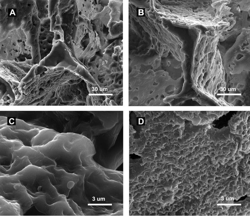
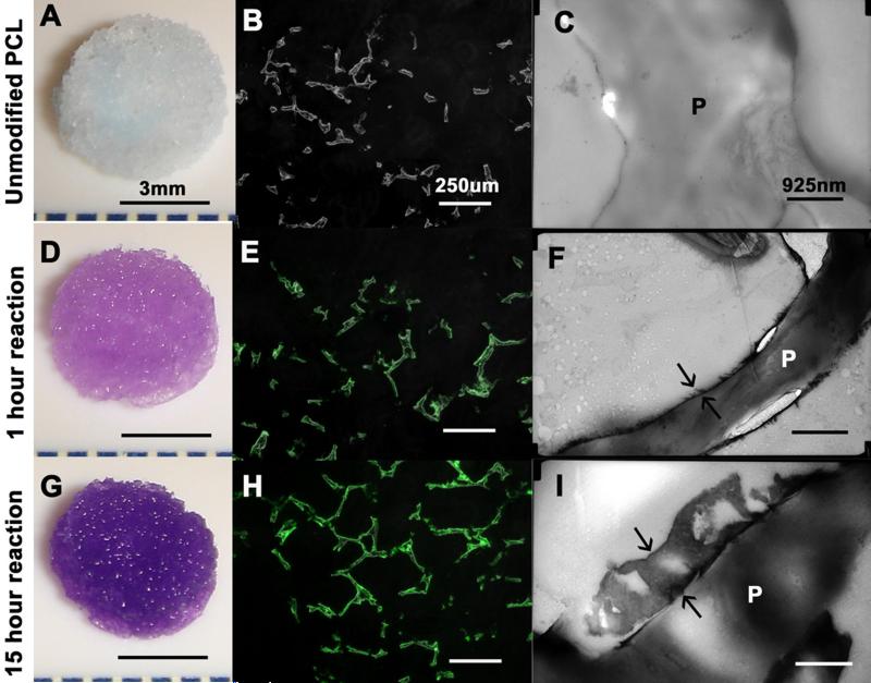
The freeze fractured scaffolds displayed a coating of heparin which rendered sub-micron roughness to surface as shown by SEM (Figure 1), The toluidine blue stain imparted purple color to the scaffolds with cross-linked heparin (Figure 2A, 2D, 2G). The quantity of heparin immobilized on the scaffold increased with prolonging the reaction time. There was 1.5 ± 1.1 μg heparin per scaffold after one hour of reaction, and 7.5 ± 1.6 μg heparin per scaffold after 15 hours of reaction. The fluorescein-conjugated heparin showed a uniform distribution of heparin over the struts without obliteration of the pore connectivity (Figure 2E, 2H). The thickness of the heparin layer increased from 50-100 nm after 1 hour of reaction to 500-800 nm after 15 hours of reaction as shown by TEM (Figure 2C, 2F, 2I). The increase in thickness of the layer corroborated the quantified content of the heparin.
Figure 1.
SEM analyses. Freeze fractured strut of PCL scaffold (A) and heparin-PCL scaffold (B). Surface topography at higher magnification of PCL scaffold (C) and heparin-PCL scaffold (D). Scale bar A, B = 30 μm, scale bar C, D = 3 μm.
Figure 2.
Heparin cross-linked on PCL scaffold for 0, 1 and 15 hours of reaction duration. Toluidine blue assay (A, D, G), fluoresceine-conjugated heparin (B, E, H) and TEM (C, F, I) displays increase in heparin content with reaction time. Arrows in F, I indicate thickness of heparin layer. “P” in C, F, I represent the strut of PCL scaffold. Scale bar A, D, E= 3 mm; scale bar B, E, H =925 nm; scale bar C, F, I=250 μm.
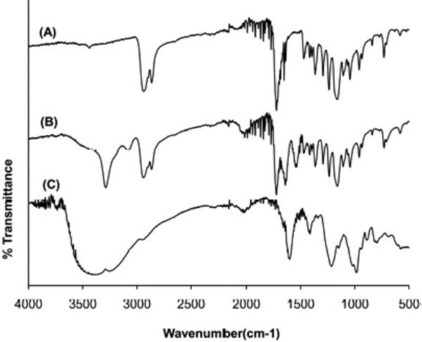
The FTIR spectra of PCL scaffold, heparin-PCL scaffold and heparin powder are shown in Figure 3. The PCL scaffold and heparin-PCL scaffolds possessed absorptions peaks at 2940 cm−1 and 2860 cm−1 representing -CH2- stretching and a peak at 1720 cm−1 representing the carbonyl group. The cross-linked heparin gave rise to a new amide C=O band at 1660 cm−1 and a band at 3400 cm−1 due to -OH stretching. The –SO3−stretching peaks in heparin powder at 1230 cm−1 and 1040 cm−1 were overlapped by the PCL related peaks in heparin-PCL scaffold.
Figure 3.
FTIR spectra of PCL scaffold (A), heparin-PCL scaffold (B) and heparin powder (C).
3.2 In vitro release and adsorption properties of VEGF
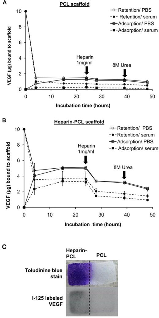
The in vitro affinity of VEGF for heparin-PCL and unmodified PCL scaffolds is shown in Figure 4. The short-term kinetic study showed an initial burst release of loaded VEGF within first 3 hours of incubation. After 24 hours, heparin-PCL retains ~4 times higher amount of VEGF as compared to PCL. In all instances, the quantity of VEGF bound to scaffold was less in the presence of serum. On spiking soluble heparin in the incubation media, ~50% of the adsorbed VEGF was released from the heparin-PCL scaffold. Abolishing the electrostatic interaction by urea released a small amount of additional bound VEGF. Nonetheless, a fraction of VEGF remained bound to the scaffold even after urea treatment.
Figure 4.
In vitro adsorption and retention of VEGF on scaffolds incubated in PBS or PBS supplemented with 10% serum. Unmodified PCL scaffold (A) and heparin-PCL scaffold cross-linked for 15 hours (B). For retention kinetics, VEGF loaded on the scaffold was allowed to release in the incubation media. For adsorption kinetics, scaffolds were allowed to adsorb VEGF added to the incubation media. At specified times during the incubation, scaffolds were exposed to soluble heparin (1 mg/ml) or, 8 M urea solution in PBS. Values represent the mean and standard deviation (n=3). PCL sheet with heparin immobilized on one half was incubated for 24 hours in PBS with1μg VEGF and 10% serum; spatial distribution of heparin and VEGF visualized by toluidine blue stain and I-125 labeled VEGF, respectively (C).
The VEGF retention property of scaffold was assessed for varying doses of loaded VEGF and immobilized heparin. Higher amount of heparin cross-linked on PCL improved binding capability of VEGF to the scaffold and reduced the initial burst release (Figure 5). After the initial burst release, both the low heparin-PCL (1.5 μg/scaffold) and high heparin-PCL (7.5 μg/scaffold) scaffolds displayed similar VEGF release rates for up to 14 days in vitro. As the VEGF loading dose increased, the fraction of the VEGF retained by the scaffold declined. For the VEGF loading of 1, 10 and 100 μg/scaffold, the release rate of VEGF from heparin-PCL scaffolds in serum condition was approximately 10, 100 and 1000 ng/day, respectively.
Figure 5.
In vitro retention of VEGF for varying doses of immobilized heparin and loaded VEGF. VEGF retained by scaffolds after 24 hours of incubation in PBS or PBS supplemented with 10% serum (A). Long-term release kinetics of VEGF from the scaffolds loaded with 1 μg (B) 10 μg (C) and 100 μg of VEGF (D). Values represent the mean and standard deviation (n=3). V1, V10 and V100 represent scaffold loaded with 1 μg, 10 μg and 100 μg of VEGF, respectively. H0, H1 and Hm represent scaffolds without heparin, with heparin cross-linked for 1 hour and 15 hours, respectively.
3.3 Bioactivity of VEGF retained by heparin-PCL scaffold
The bioactivity of VEGF adsorbed to scaffold was assessed after washing away the unbound fraction of the growth factor with PBS (Figure 6). The VEGF bound to the scaffold was able to phosphorylate VEGFR2 receptor in endothelial progenitor cells. Furthermore, after eluting the VEGF from the scaffold with soluble heparin, the fraction of VEGF stuck to the scaffold was capable of phosphorylating VEGFR-2, although the signal was substantially weaker.
Figure 6.
Bioactivity of VEGF bound to heparin-PCL scaffold. VEGFR2 phosphorylation was assessed after endothelial progenitor cells (EPC) were exposed to following conditions for 5 minutes. Lane 1: cells in contact with scaffold sheet without VEGF as negative control; lane 2: soluble VEGF in PBS as positive control; lane 3: cells in contact with scaffold sheet loaded with VEGF and pre-washed several times with PBS; lane 4: cells in contact with scaffold sheet loaded with VEGF, pre-washed with soluble heparin and PBS.
3.4 Angiogenesis in implanted scaffolds
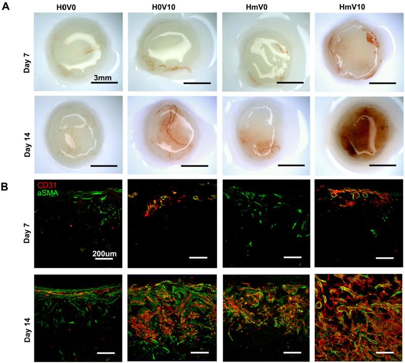
The scaffolds implanted subcutaneously in NOD-SCID mice were retrieved at day 7 and day 14. At day 7, there were sparse blood vessels in the periphery of the heparin-PCL scaffolds loaded with 10 μg of VEGF (Figure 7). At day 14, the scaffold groups exhibited distinct angiogenic response depending on the combination of heparin and VEGF presented. The scaffolds with heparin and VEGF displayed significant increase in CD31 and αSMA-positive vessels.
Figure 7.
Scaffolds harvested at day 7 and day 14. Gross image of the harvested scaffolds (A). Scaffolds were cut into 200-μm thick sections and stained with anti-CD31 and anti-αSMA antibodies (B). V0 and V10 represent scaffold without VEGF and loaded with 10 μg of VEGF, respectively. H0 and Hm represent scaffolds without heparin and with heparin cross-linked for 15 hours, respectively. Scale bar A=3 mm; Scale bar B=200 μm.
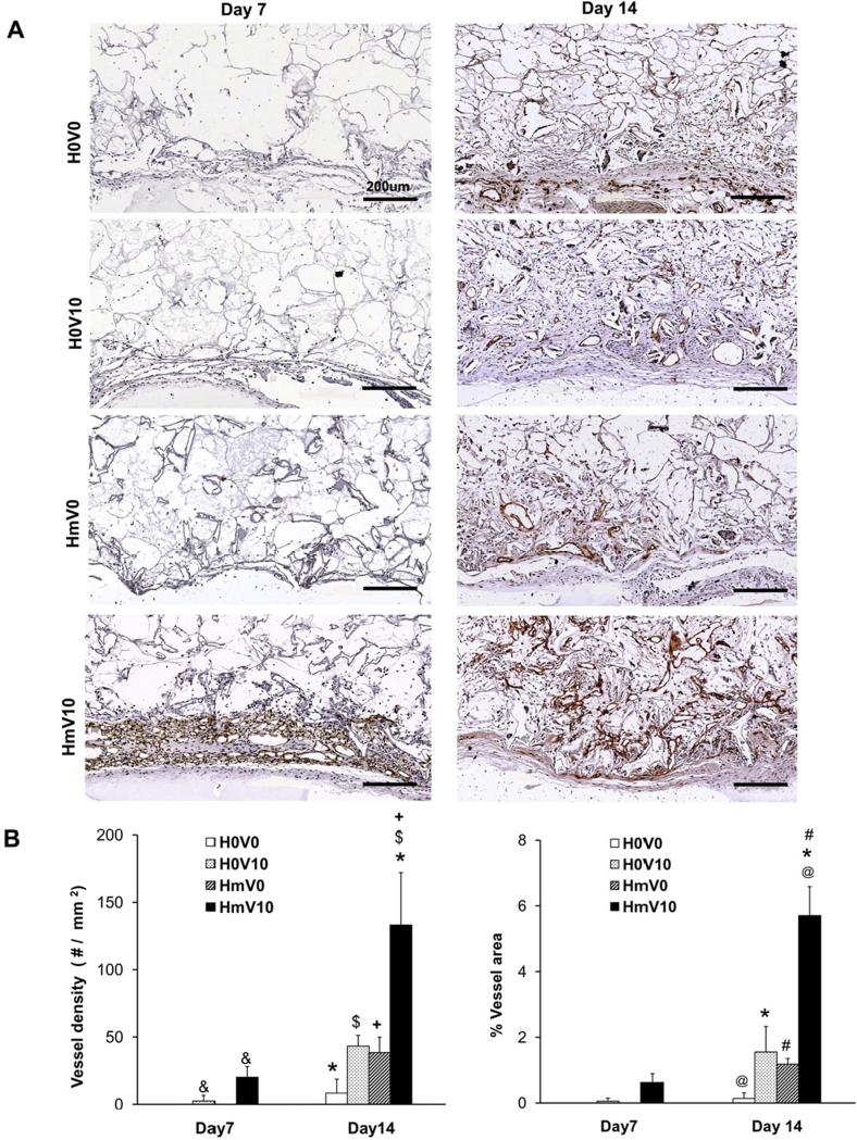
The total vessel density and percentage area occupied by vessels were quantified from the sections of the scaffold stained with anti-CD31 (Figure 8). At day 14, heparin-PCL scaffolds loaded with 10 μg of VEGF resulted in a 12-fold increase in angiogenesis over scaffolds without heparin and VEGF. The combination of heparin and VEGF displayed a 3-fold increase in vessel density and percentage area over the scaffolds with either VEGF or heparin alone.
Figure 8.
Quantification of vessels in scaffold harvested on day 7 and day 14. The scaffold sections were stained with anti-CD31 antibody (A) to quantify average vessel density (B) and percentage of scaffold area occupied by vessels (C). Values represent the mean and standard deviation (n=3). V0 and V10 represent scaffold without VEGF and loaded with 10 μg of VEGF, respectively. H0 and Hm represent scaffolds without heparin and with heparin cross-linked for 15 hours, respectively. Scale bar A=200 μm. (@) p< 0.0001, (*, #) p<0.005, ($, +, &) p<0.05.
The difference among scaffolds was further characterized by quantifying angiogenesis as a function of scaffold thickness. The anti-CD31 stained vessels were counted at intervals of 200 μm from the scaffold-tissue interface (Figure 9). At day 14, the heparin-PCL loaded with VEGF possessed the highest vessel density and percent of vessel area in the entire thickness of the scaffold compared to all other groups.
Figure 9.
Quantification of angiogenesis as a function of scaffold depth at day 14. CD31-positive vessels in scaffold sections were outlined with red, blue and green color for 0-200 μm, 200-400 μm and 400-600 μm intervals, respectively (A). The vessel density (B) and percentage of area occupied by vessels (C) was evaluated at 200-μm intervals. Values represent the mean and standard deviation (n=4). V0 and V10 represent scaffold without VEGF and loaded with 10 μg of VEGF, respectively. H0 and Hm represent scaffolds without heparin and with heparin cross-linked for 15 hours, respectively.
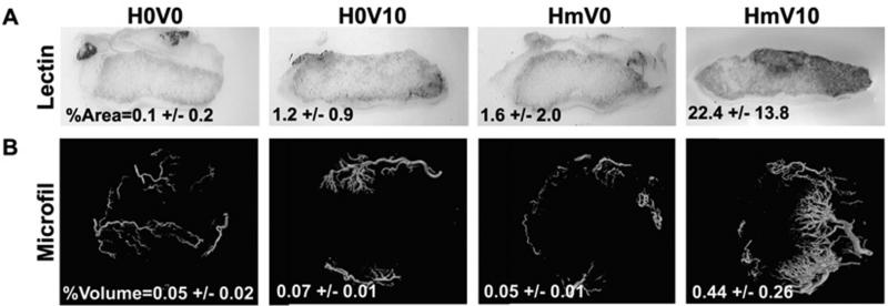
The patency and connectivity of vessels formed in the scaffolds was verified by intravenous injection of endothelium-binding biotinylated lectin. The heparin-PCL scaffold loaded with VEGF displayed highest percent of lectin perfused area (Figure 10). Furthermore, the architecture of functional vessels in the scaffold was visualized by μCT. Again, the heparin-PCL loaded with VEGF showed markedly high percent of perfusable volume in scaffold compared to other groups.
Figure 10.
Functionality of vessels in scaffold at day 14. Endothelium -binding lectin injected intra-vascularly to determine %perfusable area in 200-μm thick scaffold section (A). Microfil injected vessels were assess by μCT scan to measure total %perfusable volume (B). Values represent the mean and standard deviation (n=3). V0 and V10 represent scaffold without VEGF and loaded with 10 μg of VEGF, respectively. H0 and Hm represent scaffolds without heparin and with heparin cross-linked for 15 hours, respectively.
3.5 Effect of varying VEGF and heparin dose
To optimize our scaffold parameters, we evaluated the in vivo response upon independently varying doses of VEGF and cross-linked heparin. The CD31 positive vessels were quantified in scaffolds with 7.5 μg heparin and loaded with either 0 μg, 1 μg or, 10 μg of VEGF (Figure 11). The low heparin content (~1.5 μg/scaffold) displayed no decline in vessel density when compared to high heparin dose (~7.5 μg / scaffold) with 10 μg VEGF of loading dose. The confocal images showed the CD31-positive vessels were covered by αSMA-positive cells in both lower VEGF and lower heparin scaffold groups.
Figure 11.
Angiogenesis at day 14. Effect of low dose of VEGF (A) and effect of low dose of heparin (B). CD31-positive vessel density in scaffold sections were quantified. Values represent the mean and standard deviation (n=3). V0, V1 and V10 represent scaffold without VEGF, with 1 μg and 10 μg of VEGF, respectively. H0, H1 and Hm represent scaffolds without heparin, with heparin cross-linked for 1 hour and 15 hours, respectively. ($, +) p<0.05, ns=no significant difference. CD31-positive vessels in scaffold sections were outlined with red, blue and green color for 0-200 μm, 200-400 μm and 400-600 μm intervals, respectively.
4. Discussion
The objective of our research is to accelerate VEGF-mediated angiogenesis in the porous PCL scaffold. Since the VEGF bound to extracellular matrix is more effective in inducing formation of new vessels, we hypothesize that the binding of VEGF to the scaffold via surface-immobilized heparin would accelerate angiogenesis. The current literature reports enhanced angiogenesis in the collagen scaffolds cross-linked with heparin upon delivery of VEGF [15-18]. The follow up study by Yao et al. found that the cross-linked collagen scaffolds loaded with VEGF induced similar response even in absence of heparin. This finding emphasizes the need to reexamine the combined effect of heparin and VEGF using scaffold made from an inert synthetic biomaterial.
Other researchers have tethered heparin on different materials, such as, alginate and polyethylene glycol hydrogels, poly(L-lactic-co-glycolic acid) (PLGA) and collagen sponges, electrospun poly(L-lactide) and chitosan microspheres. In our study, we cross-linked heparin on PCL scaffold using carbodiiimde chemistry where the amine groups react with the carboxylic groups in heparin. The carbodiimide reaction has been used to modify collagen [15-17], aminated-PLGA [18] and alginate [19] scaffolds. Other technique reported in the literature is ionic complexation of heparin on protonated chitosan [20] and PCL/pluronic [21] scaffolds. The drawback of this approach is that the electrostratic-binding between heparin and the scaffold could be susceptible to changes in pH under in vivo environment. A robust alternative is to covalently incorporate functonalized heparin in the backbone of the PEG hydrogels [22].
Heparin binds to proteins because its negatively charged sulfate groups attract positively charged amino acid residues in proteins. Scaffolds with cross-linked heparin were evaluated in vitro for VEGF adsorption and release kinetics. As expected, the heparin-PCL scaffolds demonstrated lower burst release and higher retention of VEGF as compared to PCL alone. The amount of VEGF retained by the scaffold was proportional to the heparin content. The reason for increased retention of VEGF in high heparin-PCL scaffolds could be that the growth factor gets enmeshed within the thick layer of polysaccharide network. In low-heparin scaffolds, less quantity of VEGF is retained as the growth factor is adsorbed superficially by the slim layer of heparin on scaffold's surface. A similar heparin-dose dependent reduction in the initial burst release of basic fibroblast growth factor has been reported in chitosan-alginate scaffolds by others [23]. In our study, both the low heparin-PCL and high heparin-PCL scaffolds displayed a similar release rate of VEGF. This might be because the amount of adsorbed VEGF that can dissociate from the scaffold is similar in both the groups. The magnitude of the VEGF release rate could be modulated by altering the VEGF loading dose. The release rate of VEGF from heparin-PCL scaffolds varied from 10 ng/day to 1000 ng/day as the loading dose was increased from 1 μg to 100 μg.
To assess in vivo response, we implanted the scaffolds in mice and systematically compared angiogenesis in scaffolds with different combinations of VEGF and heparin doses. The heparin-PCL scaffolds loaded with 10 μg of VEGF displayed dramatically high vessel density at day 14. Extrapolation of the in vitro release kinetics of VEGF implies that a release rate of 100 ng VEGF/day induces maximum angiogenic response. This release rate is comparable to the optimal release rate of VEGF reported by other investigators [1, 24].
In the existing literature, angiogenesis is quantified in terms of the average vessel density, the percentage of area or, volume occupied by the vessels and the total hemoglobin content of the scaffold. Our study also compared angiogenesis in scaffolds by assessing vessel density and percentage of area occupied by vessels. Although, these parameters are useful, they do not reveal the distance of vessel in-growth in the scaffold. The spatial distribution of vessels is an important factor in estimating the threshold dimensions of the scaffold for clinical application. Therefore, we assessed vessel distribution as a function of distance from the scaffold edge. In heparin-PCL scaffold with 10 μg of VEGF, the significant increase in vessel density is maintained throughout the thickness of the scaffold. Since the blood vessels have to serve as conduit for delivery of oxygen and other nutrients within the scaffold, we also examined the vessel maturity and connectivity to the host circulatory system. The perfusable volume determined by micro-CT in heparin-PCL loaded VEGF was higher than that reported in PEG-hydrogel with covalently immobilized VEGF at 2 week time-point [10].
An interesting finding in our study was that there was no significant difference in angiogenesis between low heparin-PCL and high heparin-PCL scaffolds. Since increasing the heparin cross-linked on PCL improved retention of VEGF to the scaffold, we anticipated a heparin-dose dependent improvement in angiogenesis. The possible explanation for this incongruity is that the angiogenesis in scaffold depends solely on the diffusion rate of VEGF from the scaffold rather than on the amount of VEGF retained. Both the low and high heparin scaffolds released 100 ng/day of VEGF up to 14 days and therefore exhibited similar angiogenic response. We speculate that the scaffolds with high heparin content will maintain the optimal release rate of VEGF for extended duration at time-points later than 14 days. Taken together, our results indicate that optimizing the dose of VEGF and heparin is important to enhance angiogenic response within the scaffold.
5. Conclusions
Our findings demonstrate that modification of the scaffold surface with heparin is a convenient and potent approach to deliver VEGF. The heparin immobilization technique can be applied to make any biomaterial more conducive for angiogenesis. In this study, we show that the angiogenic response can be fine-tuned by modulating the dose of VEGF. As in native extracellular matrix, the scaffolds with immobilized heparin serve as growth factor reservoir and maintain a sustained release of bioactive VEGF. Our results underscore the importance of scaffold preparation in improving the efficacy of the delivered growth factor and consequently the in vivo response.
Acknowledgements
This work was funded by the National Institutes of Health R01 DK083319 and the Fubon Foundation.
Footnotes
Publisher's Disclaimer: This is a PDF file of an unedited manuscript that has been accepted for publication. As a service to our customers we are providing this early version of the manuscript. The manuscript will undergo copyediting, typesetting, and review of the resulting proof before it is published in its final citable form. Please note that during the production process errors may be discovered which could affect the content, and all legal disclaimers that apply to the journal pertain.
References
- 1.Richardson TP, Peters MC, Ennett AB, Mooney DJ. Polymeric system for dual growth factor delivery. Nat Biotechnol. 2001;19(11):1029–34. doi: 10.1038/nbt1101-1029. [DOI] [PubMed] [Google Scholar]
- 2.Lee KY, Peters MC, Mooney DJ. Comparison of vascular endothelial growth factor and basic fibroblast growth factor on angiogenesis in SCID mice. J Control Release. 2003;87(1-3):49–56. doi: 10.1016/s0168-3659(02)00349-8. [DOI] [PubMed] [Google Scholar]
- 3.Sun G, Shen Y, Kusuma S, Fox-Talbot K, J Steenbergen C, Gerecht S. Functional neovascularization of biodegradable dextran hydrogels with multiple angiogenic growth factors. Biomaterials. doi: 10.1016/j.biomaterials.2010.08.091. In press. [DOI] [PubMed] [Google Scholar]
- 4.Freeman I, Cohen S. The influence of the sequential delivery of angiogenic factors from affinity-binding alginate scaffolds on vascularization. Biomaterials. 2009;30(11):2122–31. doi: 10.1016/j.biomaterials.2008.12.057. [DOI] [PubMed] [Google Scholar]
- 5.Elcin AE, Elcin YM. Localized angiogenesis induced by human vascular endothelial growth factor-activated PLGA sponge. Tissue Eng. 2006;12(4):959–68. doi: 10.1089/ten.2006.12.959. [DOI] [PubMed] [Google Scholar]
- 6.Chiu LL, Radisic M. Scaffolds with covalently immobilized VEGF and Angiopoietin-1 for vascularization of engineered tissues. Biomaterials. 2010;31(2):226–41. doi: 10.1016/j.biomaterials.2009.09.039. [DOI] [PubMed] [Google Scholar]
- 7.Carmeliet P, Ferreira V, Breier G, Pollefeyt S, Kieckens L, Gertsenstein M, et al. Abnormal blood vessel development and lethality in embryos lacking a single VEGF allele. Nature. 1996;380(6573):435–9. doi: 10.1038/380435a0. [DOI] [PubMed] [Google Scholar]
- 8.Ferrara N, Chen H, Davis-Smyth T, Gerber HP, Nguyen TN, Peers D, et al. Vascular endothelial growth factor is essential for corpus luteum angiogenesis. Nat Med. 1998;4(3):336–40. doi: 10.1038/nm0398-336. [DOI] [PubMed] [Google Scholar]
- 9.Zisch AH, Lutolf MP, Ehrbar M, Raeber GP, Rizzi SC, Davies N, et al. Cell-demanded release of VEGF from synthetic, biointeractive cell ingrowth matrices for vascularized tissue growth. FASEB J. 2003;17(15):2260–2. doi: 10.1096/fj.02-1041fje. [DOI] [PubMed] [Google Scholar]
- 10.Phelps EA, Landázuri N, Thulé PM, Taylor WR, García AJ. Bioartificial matrices for therapeutic vascularization. Proc Natl Acad Sci USA. 2010;107(8):3323–8. doi: 10.1073/pnas.0905447107. [DOI] [PMC free article] [PubMed] [Google Scholar]
- 11.Carmeliet P, Ng YS, Nuyens D, Theilmeier G, Brusselmans K, Cornelissen I, et al. Impaired myocardial angiogenesis and ischemic cardiomyopathy in mice lacking the vascular endothelial growth factor isoforms VEGF164 and VEGF188. Nat Med. 1999;5(5):495–502. doi: 10.1038/8379. [DOI] [PubMed] [Google Scholar]
- 12.Gerhardt H, Golding M, Fruttiger M, Ruhrberg C, Lundkvist A, Abramsson A, et al. VEGF guides angiogenic sprouting utilizing endothelial tip cell filopodia. J Cell Biol. 2003;161(6):1163–77. doi: 10.1083/jcb.200302047. [DOI] [PMC free article] [PubMed] [Google Scholar]
- 13.Ruhrberg C, Gerhardt H, Golding M, Watson R, Ioannidou S, Fujisawa H, et al. Spatially restricted patterning cues provided by heparin-binding VEGF-A control blood vessel branching morphogenesis. Genes Dev. 2002;16(20):2684–98. doi: 10.1101/gad.242002. [DOI] [PMC free article] [PubMed] [Google Scholar]
- 14.Brandner B, Kurkela R, Vihko P, Kungl AJ. Investigating the effect of VEGF glycosylation on glycosaminoglycan binding and protein unfolding. Biochem Biophys Res Commun. 2006;340(3):836–9. doi: 10.1016/j.bbrc.2005.12.079. [DOI] [PubMed] [Google Scholar]
- 15.Nillesen ST, Geutjes PJ, Wismans R, Schalkwijk J, Daamen WF, van Kuppevelt TH. Increased angiogenesis and blood vessel maturation in acellular collagen-heparin scaffolds containing both FGF2 and VEGF. Biomaterials. 2007;28(6):1123–31. doi: 10.1016/j.biomaterials.2006.10.029. [DOI] [PubMed] [Google Scholar]
- 16.Steffens GC, Yao C, Prével P, Markowicz M, Schenck P, Noah EM, et al. Modulation of angiogenic potential of collagen matrices by covalent incorporation of heparin and loading with vascular endothelial growth factor. Tissue Eng. 2004;10(9-10):1502–9. doi: 10.1089/ten.2004.10.1502. [DOI] [PubMed] [Google Scholar]
- 17.Yao C, Markowicz M, Pallua N, Noah EM, Steffens G. The effect of cross-linking of collagen matrices on their angiogenic capability. Biomaterials. 2008;29(1):66–74. doi: 10.1016/j.biomaterials.2007.08.049. [DOI] [PubMed] [Google Scholar]
- 18.Jeon O, Song SJ, Kang S, Putnam AJ, Kim B. Enhancement of ectopic bone formation by bone morphogenetic protein-2 released from a heparin-conjugated poly(L-lactic-co-glycolic acid) scaffold. Biomaterials. 2007;28(17):2763–71. doi: 10.1016/j.biomaterials.2007.02.023. [DOI] [PubMed] [Google Scholar]
- 19.Ohta M, Suzuki Y, Chou H, Ishikawa N, Suzuki S, Tanihara M, et al. Novel heparin/alginate gel combined with basic fibroblast growth factor promotes nerve regeneration in rat sciatic nerve. J Biomed Mater Res A. 2004;71(4):661–8. doi: 10.1002/jbm.a.30194. [DOI] [PubMed] [Google Scholar]
- 20.Jiang T, Khan Y, Nair LS, Abdel-Fattah WI, Laurencin CT. Functionalization of chitosan/poly(lactic acid-glycolic acid) sintered microsphere scaffolds via surface heparinization for bone tissue engineering. J Biomed Mater Res A. 2010;93(3):1193–208. doi: 10.1002/jbm.a.32615. [DOI] [PubMed] [Google Scholar]
- 21.Im G, Lee JH. Repair of osteochondral defects with adipose stem cells and a dual growth factor-releasing scaffold in rabbits. J Biomed Mater Res Part B Appl Biomater. 2010;92(2):552–60. doi: 10.1002/jbm.b.31552. [DOI] [PubMed] [Google Scholar]
- 22.Kim M, Lee JY, Jones CN, Revzin A, Tae G. Heparin-based hydrogel as a matrix for encapsulation and cultivation of primary hepatocytes. Biomaterials. 2010;31(13):3596–603. doi: 10.1016/j.biomaterials.2010.01.068. [DOI] [PMC free article] [PubMed] [Google Scholar]
- 23.Ho YC, Mi FL, Sung HW, Kuo PL. Heparin-functionalized chitosan-alginate scaffolds for controlled release of growth factor. Int J of Pharm. 2009;376(1-2):69–75. doi: 10.1016/j.ijpharm.2009.04.048. [DOI] [PubMed] [Google Scholar]
- 24.Davies N, Dobner S, Bezuidenhout D, Schmidt C, Beck M, Zisch AH, et al. The dosage dependence of VEGF stimulation on scaffold neovascularisation. Biomaterials. 2008;29(26):3531–8. doi: 10.1016/j.biomaterials.2008.05.007. [DOI] [PubMed] [Google Scholar]


