Abstract
Along with insights into the potential for graft success, knowledge of biomechanical properties of small diameter tissue-engineered blood vessel (TEBV) will enable designers to tailor the vessels' mechanical response to closer resemble that of native tissue. Composed of two layers that closely mimic the native media and adventitia, a tissue-engineered vascular adventitia (TEVA) is wrapped around a tissue-engineered vascular media (TEVM) to produce a self-assembled tissue-engineered media/adventia (TEVMA). The current study was undertaken to characterize the biaxial biomechanical properties of TEVM, TEVA and TEVMA under physiological pressures as well as characterize the stress-free reference configuration. It was shown that the TEVA had the greatest compliance over the physiological loading range while the TEVM had the lowest compliance. As expected, compliance of the SA-TEBV fell in between with an average compliance of 2.73 MPa−1. Data were used to identify material parameters for a microstructurally motivated constitutive model. Identified material parameters for the TEVA and TEVM provided a good fit to experimental data with an average coefficient of determination of 0.918 and 0.868, respectively. These material parameters were used to develop a two-layer predictive model for the response of a TEVMA which fit well with experimental data.
Keywords: vascular biomechanics, constitutive modelling, arteries, tissue engineering, finite deformation
1. Introduction
Cardiovascular disease (CVD) is the leading cause of death in the US; more specifically, coronary artery disease accounts for 54 per cent of all CVD and 20 per cent of mortality in the US, with an estimated economic cost of $142.5 billion [1]. Over half a million coronary by-pass procedures are performed in the US each year; however, it is estimated that 30–50% of all coronary by-pass grafts will result in restenosis, requiring additional clinical intervention [1]. One often cited cause for such restenosis is a ‘compliance mismatch’ between the native and grafted tissues. In addition, for many patients, suitable autologous grafting tissues are not available. This clinical need could be met through the development of small diameter tissue-engineered blood vessels (TEBVs) with low thrombogenicity and immune responses, suitable mechanical properties and a capacity to remodel to their local environment [2–5].
Different platforms for developing a suitable TEBV graft have shown great promise; these include gel-derived [6,7], polymeric biodegradable scaffold-derived [8] and self-assembly-derived TEBVs [9]. Interestingly, TEBVs constructed by self-assembly (SA-TEBV) have shown superior mechanical strength (burst pressure more than 1000 mmHg), morphology, structural organization and vasomotor response compared with other TEBVs [2,10–16]. The self-assembly approach consists of culturing human umbilical smooth muscle cells (hUSMCs) and dermal fibroblasts (hDFs) in supplemented culture media; after several weeks the cells form a thick living tissue sheet that can be rolled around a mandrel and cultured to form a TEBV with layers similar to the media and adventitia of native vessels. Endothelial cells (ECs) can be seeded on the luminal surface to form a functioning endothelium [17].
Mismatched biomechanical properties between the graft and native surrounding tissue are commonly cited as a cause of graft failure. Given these observations, we submit that design criteria that minimize mechanically induced restenosis in vascular grafts include: (i) matching the inner diameter of the host and the graft at physiological pressure and axial stretch; (ii) matching the compliance of the host and graft over the cardiac cycle; (iii) matching the axial force imposed by the graft on the host vessel under physiological loading; and (iv) matching the local circumferential and axial wall stresses of the graft to near homeostatic values of the native vasculature. The latter criteria will ensure that there are no significant changes in geometry or material properties after implant due to plasticity, fatigue or remodelling.
A constitutive model describing the mechanical response of the tissue to applied loads is required to predict the diameter, compliance, axial force and local distribution of stresses across the vessel wall for a native or engineered blood vessel given a particular applied load (e.g. physiological loading). The goal of the current study is to characterize the biaxial biomechanical behaviour of the tissue layers that comprise SA-TEBVs and identify a predictive constitutive model. Using a novel bioreactor and biomechanical testing device [18], biaxial biomechanical characterization of tissue-engineered vascular media (TEVM), tissue-engineered vascular adventitia (TEVA) and two-layer tissue-engineered vascular media–adventitia (TEVMA) was performed. These data were used to identify material parameters for TEVM and TEVA using the constitutive model of Baek et al. [19]. We found that the compliances of the TEVM, TEVA and TEVMA were within the range of values reported for coronary arteries taken from the literature. In addition, these vessels are pseudo-elastic and nearly incompressible over physiological loading. Identified material parameters for TEVM and TEVA provide a good fit to experimental data and predict the mechanical response of TEVMA well. Such predictive models can serve as a tool to quantify deformation to applied loads and local stresses and perform design analyses to indentify new fabrication strategies to control the SA-TEBV mechanical response.
2. Methods
2.1. Cell isolation and construct fabrication
hDFs were isolated from a human skin biopsy as previously described [2]. Briefly, the dermis was separated from the epidermis by incubation in thermolysin (Sigma, Oakville, Ontario, Canada). hDF were enzymatically dissociated from the dermis using collagenase H (Roche, Indianapolis, IN), centrifuged, plated in tissue culture flasks and cultured in Dulbecco-Vogt modified Eagle medium (DMEM; Invitrogen, Burlington, Ontario, Canada) supplemented with 10 per cent foetal bovine serum (FBS; Hyclone, Logan, UT) and antibiotics (penicillin (100 U ml−1, Sigma, Oakville, Ontario, Canada), gentamicin (25 µg ml−1, Schering, Pointe-Claire, Quebec, Canada)). SMCs were isolated from a human umbilical cord (hUSMCs). An umbilical cord was obtained from a healthy newborn and processed immediately. The umbilical vein was rinsed with phosphate buffered saline, opened longitudinally and pinned to a dissection board with the lumen facing upward. EC were gently scraped from the underlying basement membrane using a scalpel blade without grossly damaging the subendothelial layer. Bands of the thin underlying media layer were then collected, cut into smaller pieces and placed in a gelatin-coated Petri dish to allow the outgrowth cells to attach to the gelatin. Explants were cultured in DMEM with Ham's F12 (ratio 3 : 1; Invitrogen, Burlington, Ontario, Canada) supplemented with 10 per cent FBS and antibiotics until cells migrated out of the biopsy samples. Freshly isolated cells were frozen for long-term storage and subsequent use. Cells between passages 3 and 7 were used for tissue production.
The tissue-engineered vascular constructs were developed as previously described [2]. Briefly, hUSMCs or hDFs were seeded at a density of 1 × 10⁴ cells cm−2 in tissue culture flasks and cultured in DMEM supplemented with 10 per cent FBS. Antibiotics were added to DMEM and sodium L-ascorbate (50 µg ml−1, Sigma, Oakville, Ontario, Canada) was added to the culture medium of vascular constructs to stimulate extracellular matrix (ECM) synthesis. Cells were cultured for 28 days until their neosynthesized ECM proteins had self-assembled into an adherent living tissue sheet, which was then gently detached from the culture flask using fine forceps; the thickness of the tissue sheet is approximately 100 µm. The tissue sheet was wrapped around a polystyrene tube of 4.5 mm diameter approximately five times and maintained in culture in DMEM-Ham (3 : 1) supplemented with 10 per cent bovine Foetal Clone II serum (HyClone), antibiotics and 50 µg ml−1 of sodium ascorbate. TEVM were developed by wrapping sheets formed from hUSMCs. TEVA were developed by wrapping tissue sheets formed from hDF.
The production of the TEVMA used a new and original technique allowing the fabrication of the TEVMA in a single step assembly (ssTEVMA). SMCs and DFs were seeded in two distinct compartments of a tissue culture plate (Corning, Lowell, MA) separated by a custom designed spacer. The spacer was removed 24 h following cell seeding in order to allow cell adhesion to the underlying tissue culture plastic. The two cell types migrate towards each other to form a continuous sheet of tissue with two distinct areas containing SMCs and DFs with an integrated region at their interface [20]. The spacer was placed in the centre of the tissue culture flask to maintain a ratio of media to adventitia thickness of 0.5. All vascular constructs were maintained for a 14-day-culture period on the tubular support at 37°C in a humidified incubator containing 8 per cent CO2. The culture medium was changed three times per week. Note that vessels were grown and fabricated in the Laboratoire d'Organogénèse Expérimentale (LOEX) in Quebec City, Quebec, Canada. Two weeks after the tissue sheets were wrapped around the tubular mandrel, the vessels were shipped overnight to the Georgia Institute of Technology in Atlanta, GA, USA for biomechanical testing.
2.2. Biaxial biomechanical testing
Ring sections, approximately 2 mm wide, were cut from the construct prior to biomechanical testing to determine if the traction-free configuration contained residual stress. With the vessel still on the mandrel, a scalpel was used to remove a 4 mm section from the end of the vessel and discarded. The ring section was subsequently cut from the remaining length of the construct. These sections were gently removed from the mandrel using forceps and placed into a tissue culture dish containing culture media at 37°C. Each ring was imaged on an inverted microscope (Zeiss, Axiovert 40C) equipped with a digital camera. Without moving the sample, fine scissors were used to impose a radial cut in the ring while suspended in the culture media. An image of the cut section was taken on the same device and opening angle information was processed in Matlab (MathWorks, Inc.).
Cylindrical biaxial biomechanical testing was performed on the vascular constructs using a custom-built bioreactor [18]. Each construct was mounted to the cannula using silicon o-rings and submerged in the same formulation of culture media in which the tissue sheets were grown. After the TEBV was mounted in the device and placed in the incubator, a minimum of 30 min was given for the TEBV and culture medium to equilibrate to the incubator environment. Immediately prior to testing, three preconditioning cycles to 50 mmHg were performed. Following preconditioning, the unloaded length is set by the stretching the vessel under 0 mmHg until a small preload (2 g) is registered on the load cell; the vessel's unloaded length was measured as the distance between each o-ring using a digital caliper. The testing protocol consisted of three inflation/deflation cycles to 150 mmHg at a rate of 2 mmHg s−1 at fixed axial stretches of λz = 1.0, 1.1, 1.2 and 1.3 for the TEVA and TEVMA and λz = 1.0, 1.1 and 1.2 for the TEVM, while monitoring the outer diameter and axial force in real time. The axial stretch is defined as λz = l/L0 where l is the loaded length and L0 is the unloaded length. An ultrasound probe was used to measure the vessel wall thickness.
2.3. Stress–strain response
With measured values of the axial force, transmural pressure, axial stretch, outer diameter and wall thickness, stress analyses may be performed. The mid-wall circumferential Green strain
| 2.1 |
was used, where λθ represents the circumferential stretch ratio. The circumferential stretch is defined as λθ = d/D0 with d as the loaded midwall diameter and D0 the unloaded midwall diameter. Note that unlike linearized measures of strain, the Green strain is an appropriate strain measure for large deformations. The mean circumferential stress ( ) and mean axial stress (
 ) are
) are
| 2.2 |
respectively, where P is the transmural pressure, f the axial force, a the lumen radius and h the thickness of the vessel wall. For all three vessel types, incompressibility was assumed for the stress analysis; thus, det(F) = 1. Compliance over the physiological pressure range may be defined through the relation
| 2.3 |
where C is compliance, ΔP the pressure difference between systolic pressure and diastolic pressure, Δɛ the local linearized cyclic strain experienced over ΔP,  the midwall radius at systolic pressure,
  the midwall radius at diastolic pressure and
  the midwall radius at mean pressure.
2.4. Constitutive modelling
2.4.1. Theoretical framework
Our biomechanical testing data suggest that finite elasticity is an appropriate framework to model the pseudo-elastic response of these tissues. Thus, these tissue-engineered vessels will be modelled as a nonlinear, elastic, anisotropic, incompressible solid which experience large deformations. The TEVM and TEVA are assumed to be homogeneous, as is each layer of the TEVMA. The kinematics and constituent strain energy functions for each layer are distinct due to differences in the stress-free reference state and material response of each layer [21]; we shall follow this approach.
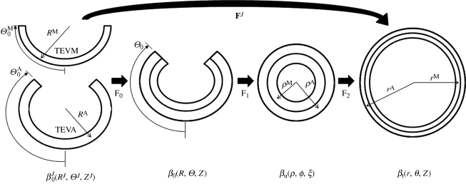
For inflation and extension of a two-layer, axisymmetric tube, with each layer possessing residual-stress in the traction-free state, one typically considers four configurations when performing stress analyses: a current (loaded) configuration (βt), the traction-free, unloaded configuration (βu) and a (nearly) stress-free configurations of each layer ( and
and  ; figure 1). Thus, we must specify the stress-free configuration for the media (
 ,
,  , ΛM and
  ) and the stress-free configuration for the adventitia (
 ,
,  , ΛA and
  ), where
  is the outer radius,
  the inner radius, ΛJ the axial stretch and
  the opening angle (J = M or A, denoting media and adventitia, respectively). Note that
  and
and  are one measure of the opening angle which occurs when a single radial cut is imposed in a vessel ring in the unloaded configuration. The deformation gradients, FM and FA, are the gradients of the map that take points from an appropriate stress-free configuration (
 and
and  , respectively) to the loaded configuration (βt); the components of FJ and CJ, the right Cauchy–Green deformation tensor, are diagonal matrices, given as
 |
2.4 |
where λz and ΛJ are axial stretches for the motion from βu to βt and  to βu, respectively. Finally, given the incompressibility assumption, det[FJ] = 1; thus
 |
2.5 |
where ro is the outer radii of the vessel in βt and r and RJ are the radius of interest in  and βt (figure 1). In the framework of finite elasticity, the Cauchy stress is defined as T = −pI +2·FJ·(∂WJ/∂CJ)·(FJ)T, where I is the identity tensor and WJ is the strain energy density function for material J and p is the Lagrange multiplier that arises due to the incompressibility constraint.
Figure 1.
Kinematics for inflation and extension of a two-layer elastic cylinder.
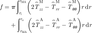
The equations of equilibrium for a two-layer vessel may be written as
 |
2.6 |
and
 |
2.7 |
where rMA is the radial location of the media–adventitia interface in the loaded configuration (βt) and  , where i = r, θ or z. Note that f in equation (2.7) is adjusted for the axial force generated from end-cap pressure existing in all in vitro biaxial testing devices.
For single layer vessels (i.e. TEVM and TEVA) equations (2.6) and (2.7) reduce to
 |
2.8 |
where J = M for TEVM and J = A for TEVA.
2.4.2. Constitutive model
We used the strain energy function of Baek et al. [19], which is a simple extension of the model of Holzapfel et al. [22] for each layer. This strain energy function is
 |
2.9 |
where bJ,  and
and  are material parameters,
  is the first invariant of CJ,
  is the stretch of the kth fibre family, and
  is the associated angle between the axial and fibre directions. For inflation and extension tests (given appropriate material symmetry),
  , so that
  . We considered four fibre families with
  ,
,  ,
,  .
.
2.4.3. Parameter identification
Material parameters were determined for TEVM and TEVA via a nonlinear regression technique that minimized the error between measured values of P and f and calculated values of P and f from equations (2.8)1 and (2.8)2 given measured values of outer diameter and length under these measured values of P and f and the measured stress-free configuration. We seeked to identify material parameters via nonlinear regression that minimize the error function:
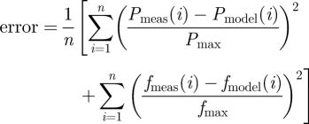 |
2.10 |
which quantifies the difference between experimental data and modelling predictions for n data points. Pmax and fmax are the maximum pressure and axial force in their respective dataset. Calculations were performed in Matlab using the lsqnonlin subroutine which allows the prescription of upper and lower limits on the parameter values. The lower and upper limits of the parameters were prescribed as  Pa,
Pa,  and αJ∈ [0°, 90°],
2.4.4. Evaluate predictive capability of model
Using the material parameters determined for the TEVM and TEVA, the mechanical response of a two-layer TEVMA was predicted using this constitutive model. Namely, the unloaded geometry and pressure from the experimental data were used to calculate the outer diameter and axial force via equations (2.6) and (2.7). The model predictions were compared with experimental data from the TEVMA using a standard R2 value to evaluate the predictive capability of the model and material parameters.
3. Results
3.1. Pseudoelastic response and incompressibility
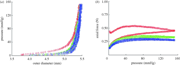
Three inflation/deflation cycles were performed at each axial stretch to ensure consistency of the sample response. Between cycles 1 and 2, there was a slight shift of the pressure–diameter curve of approximately 40 µm at 150 mmHg (figure 2a) for a representative TEVA. However, there were negligible differences in the pressure–diameter curves (less than 10 µm at 150 mmHg) between cycle 2 and all subsequent cycles. Not only was there a shift at the maximum pressure tested, there was also a notable shift throughout the pressure range. There was more hysteresis occurring during the first cycle than in the other two cycles. These same trends were seen with the axial force (figure 2b) as a 0.12 N shift occurs at 150 mmHg between cycles 1 and 2, while all subsequent cycles had a much smaller shift (less than 0.05 N). This plot also provided insight into the energy dissipation of the vascular construct between loading and unloading. Only a small degree of hysteresis is observable following the first loading/unloading cycle; thus, finite elasticity is an appropriate framework for stress analysis of these so-called pseudo-elastic materials. This response is not limited to the TEVA, but is also seen in TEVM and TEVMA. Upon unloading following mechanical testing, the unloaded length was between λz = 1.02 and 1.05. Thus, there is a small amount of plastic deformation and/or creep which occurs during testing. Importantly, this response is similar in native arteries; nevertheless, since the amount of irreversibility is small, we neglect this and model native and SA-TEBVs as a nonlinear elastic solid.
Figure 2.
(a) Biomechanical repeatability occurs after the first cycle for pressure–diameter and (b) axial force–pressure responses of TEVA (shown at an axial stretch of 1.2). The repeatability is also seen in the other two construct types (open circle, cycle 1; open inverted triangle, cycle 2; open square, cycle 3).
Small differences (less than 50 µm) are observed when comparing the measured wall thickness of a TEVA to the predicted thickness assuming incompressibility with reference to the unloaded configuration, throughout the inflation/deflation cycle (not shown). Similar results were obtained with the TEVM and TEVMA.
3.2. Opening angle
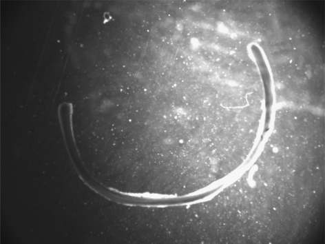
A representative image of the opening angle of a TEVMA (figure 3) indicates an angle of 107°. The experimental methods used to determine the opening angle for each vessel must be performed extremely carefully to avoid impacting the results. Table 1 shows the unloaded geometry as well as opening angle information for all of the vessels tested. Additionally, this table shows mean and standard deviations for each vessel type. There was a large variability in the opening angle measurements. It should be noted that some constructs exhibited residual stresses in other directions as indicated by a twisting of the ring in the circumferential direction; these deformations, however, were not quantified.
Figure 3.
Representative image of opening angle for TEVA in culture media at 37°C; taken from an inverted microscope. Results suggest residual stresses are developed in the vessel during maturation.
Table 1.
Vascular geometry in the unloaded configuration as well as opening angle data (measured as arc length) for all construct types. Measured compliance over physiological range (80–120 mmHg) calculated using equation (2.4). n.a., not applicable.
| construct | number | opening angle (°) | unloaded OD (mm) | unloaded thickness (µm) | unloaded length (mm) | compliance (MPa−1) |
|---|---|---|---|---|---|---|
| TEVA | 1 | n.a. | 5.35 | 518 | 24.45 | 2.90 |
| 2 | 32.25 | 5.32 | 614 | 25.35 | 2.11 | |
| 3 | 44.5 | 5.36 | 574 | 26.11 | 3.55 | |
| 4 | 81.25 | 5.57 | 571 | 27.48 | 3.25 | |
| 5 | 107 | 5.43 | 498 | 28.40 | 2.97 | |
| mean | 66.25 | 5.41 | 555 | 26.36 | 2.96 | |
| s.d. | 34.23 | 0.10 | 46.5 | 1.59 | 0.54 | |
| TEVM | 1 | 0 | 4.92 | 400 | 16.5 | 2.64 |
| 2 | 133 | 4.77 | 360 | 28.0 | 2.61 | |
| 3 | 9 | 5.03 | 429 | 25.1 | 2.52 | |
| mean | 47.33 | 4.91 | 397 | 23.2 | 2.59 | |
| s.d. | 74.33 | 0.13 | 34.6 | 5.98 | 0.06 | |
| TEVMA | 1 | 135 | 5.12 | 485 | 26.02 | 3.31 |
| 2 | 0 | 5.04 | 515 | 27.50 | 2.90 | |
| 3 | 100 | 4.98 | 442 | 26.11 | 2.81 | |
| 4 | 10 | 4.98 | 396 | 24.38 | 1.90 | |
| mean | 61.25 | 5.03 | 459.5 | 26 | 2.73 | |
| s.d. | 66.63 | 0.07 | 51.79 | 1.28 | 0.59 |
3.3. Biaxial biomechanical behaviour
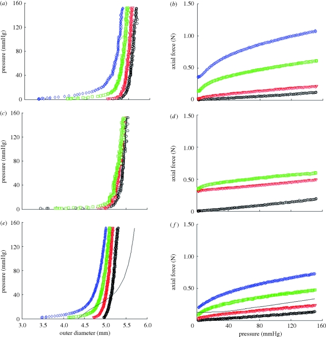
Representative results of pressure—outer diameter and axial force—pressure curves for TEVA (figure 4a,b), TEVM (figure 4c,d) and TEVMA (figure 4e,f) indicate a difference between the three construct types. The biaxial biomechanical response of a human coronary artery at an axial stretch of λ = 1.1 is shown (figure 4e,f) to compare the response of a native vasculature to that of a tissue-engineered vessel. This response is generated from the model and material parameters determined by Holzapfel et al. [22]. There was a definitive difference between the responses of the two vessels at lower pressures; however, the response became much more similar within the physiological range.
Figure 4.
Representative biaxial biomechanical response of a (a,b) TEVA, (c,d) TEVM and (e,f) TEVMA with a representative coronary artery using the constitutive model and material parameters of Holzapfel et al. [35] during standard cyclic inflation testing at fixed axial length (circle, λ = 1; open inverted triangle, λ = 1.1; open square, λ = 1.2; open diamond, λ = 1.3; solid line, coronary).
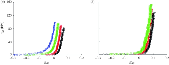
Because the pressure–diameter response depends on both material properties and geometry, it is difficult to quantify differences in the material properties between different vessels from these plots. Stress–strain plots, however, only depend on material properties; thus, differences in the stress–strain response indicate differences in the material properties. Using equations (2.2a) and (2.2b) and the incompressibility assumption, mean circumferential Cauchy stress–circumferential Green strain plots were generated for a representative TEVA and TEVM (figure 5a,b) for the fixed length inflation tests. There were distinct differences in the stress analysis between the two construct types further suggesting that there were differences in material properties.
Figure 5.
Mean circumferential Cauchy stress versus circumferential Green strain for a representative (a) TEVA and (b) TEVM at fixed axial stretches (circle, λ = 1; open inverted triangle, λ = 1.1; open square, λ = 1.2; open diamond, λ = 1.3).
3.4. Constitutive modelling
Material parameters were identified for each TEVM and TEVA tested (table 2). Final parameter values were insensitive to initial parameter values used in the nonlinear regression solver algorithm. The high R2 values suggested that these parameters provided a good fit to data. A representative example of the model fitting the experimental biaxial biomechanical properties can be seen in figure 6a,b; this figure illustrates fitting for a representative TEVA. The model fit TEVA constructs better than the TEVM as indicated by the higher R2 value. While alpha is not experimentally determined, the value of this structural parameter remains critical. Small changes in alpha lead to a much lower R2 value and thus poor predictive capability of the model.
Table 2.
Material parameters for TEVM and TEVA using constitutive equation (2.9) by minimizing the error between experimental data and model predictions (equation (2.10)) via nonlinear regression.
| vessel | bJ(kPa) | b11J(kPa) |  |
 |
 |
 |
 |
αJ | R2 |
|---|---|---|---|---|---|---|---|---|---|
| TEVM no. 1 | 0.10 | 56.82 | 29.84 | 2.38e − 4 | 64.64 | 65.54 | 16.26 | 51.60 | 0.927 |
| TEVM no. 2 | 65.02 | 64.86 | 19.68 | 24.09 | 1e − 5 | 1.19e − 6 | 100 | 19.06 | 0.866 |
| TEVM no. 3 | 83.96 | 0.282 | 31.36 | 45.06 | 1e − 5 | 0.159 | 27.84 | 66.54 | 0.811 |
| mean | 49.69 | 40.65 | 26.96 | 23.05 | 21.55 | 22.38 | 48.03 | 45.74 | 0.868 |
| s.d. | 43.98 | 35.19 | 6.35 | 22.55 | 37.32 | 37.39 | 45.38 | 24.28 | 0.063 |
| TEVA no. 1 | 0.10 | 20.43 | 5.212 | 24.87 | 1.33 | 59.71 | 32.11 | 57.83 | 0.922 |
| TEVA no. 2 | 0.10 | 1.815 | 17.08 | 32.19 | 0.88 | 11.74 | 16.49 | 59.07 | 0.912 |
| TEVA no. 3 | 0.10 | 10.07 | 19.17 | 26.23 | 1.78 | 35.62 | 10.95 | 45.90 | 0.942 |
| TEVA no. 4 | 0.10 | 40.21 | 16.49 | 22.94 | 0.61 | 60.78 | 7.305 | 52.20 | 0.880 |
| TEVA no. 5 | 0.10 | 39.13 | 22.60 | 49.40 | 0.12 | 34.75 | 8.391 | 45.09 | 0.931 |
| mean | 0.10 | 22.33 | 16.11 | 31.13 | 0.94 | 40.52 | 15.05 | 52.02 | 0.918 |
| s.d. | 0 | 17.15 | 6.55 | 10.79 | 0.64 | 20.40 | 10.18 | 6.50 | 0.032 |
Figure 6.
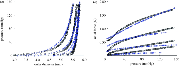
(a) Pressure–diameter (R2 = 0.892) and (b) axial force–pressure (R2 = 0.971) for TEVA no. 5 (black circles) and model predictions using the parameters for TEVA no. 5 from table 2 (blue pluses).
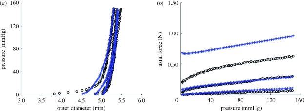
The parameters identified for the TEVA and TEVM constructs were used to predict the biaxial response of the TEVMA. Comparing the experimental values to the predicted values, the model was a good predictor of the material response of the two layer construct; a representative example of the model's biaxial biomechanical predictive capabilities is seen in figure 7a,b. Owing to the deviations in the parameters within the TEVM (table 2), using the mean values of these parameters in the two-layer model introduced large errors into the predictive model. Therefore, a combinatorial approach was taken to determine which TEVM, paired with the mean values for the TEVA produced the smallest mean error in predicting the TEVMA response. While all sets of parameters produced reasonably good fits, it was found that TEVM no. 1 could be used to best predict the two-layer response with an average R2 value of 0.424. However, most of these errors are associated with a specific loading region; namely, discrepancies arise at low pressures and high axial stretches. This is probably due to the model predicting a less compliant response in the axial direction and a manifestation of the over prediction of axial force at higher axial stretches as seen in figure 6b. The average R2 value of the pressure–diameter plots alone was 0.673. These errors illustrate that, given the highly nonlinear nature of this model the range of strains over which this model provides good predictive capabilities is limited to the range of strains of the experimental data over which the model was originally fit. Thus, the constitutive model (equation (2.9)) with identified material parameters is suitable for subsequent mechanical design analysis to optimize fabrication strategies for self-assembly TEVMA.
Figure 7.
(a) Predicted pressure–diameter (R2 = 0.838) and (b) axial force–pressure (R2 = 0.439) of TEVMA (blue pluses) using the material parameters from table 2 along with experimental measurements (black circles).
4. Discussion
It has been a long-held belief that matching biomechanical properties between the native vasculature and a vascular graft is a necessary design target to achieve long-term patency [23]. Although it is recognized that restenosis following vascular by-pass grafting is a multifactorial phenomenon, mechanically mediated adaptations play a key role in restenosis. Traditionally, saphenous veins have been used for coronary by-pass grafting; in their native environment, these veins experience an order-of-magnitude lower shear stresses, much lower mean and cyclic pressures, and higher radius to thickness ratio when compared with coronary arteries. Thus, following implantation of a saphenous vein into the arterial system, the shear stress and circumferential stress slightly increase, while the cyclic pressure and cyclic strain dramatically increase. Typically, veins are implanted at a fairly low axial stretch, thus the axial stress probably decreases. These altered loads can induce significant remodelling in the graft vessel. Grafts derived from the arterial system (e.g. internal mammary artery (IMA) or radial artery) experience less dramatic, but still significantly, altered loading following implant. Thus, the IMA often grows in a tortuous fashion, indicating maladaptive remodelling due to insufficient axial loading [24].
In addition to graft remodelling, the host vessel experiences significant changes in the local loads near the anastomosis, including altered cyclic strains due to compliance mismatch between the host and graft and altered haemodynamics due to diameter and compliance mismatch. Host tissues experience oscillatory shear stress and a significant reduction in cyclic strain; both mechanical stimuli are associated with intimal hyperplasia (IH) and plaque formation. Comparing autologous (compliant) to synthetic (non-compliant) grafts, it was found that the 2 year patency rate of compliant grafts was more than two times superior than the patency rate of non-compliant grafts [23]. This experiment, however, brings into question the resulting effect of synthetic graft biocompatibility. To eliminate synthetic materials from the experiment, [25] chemically cross-linked arterial autografts with glutaraldehyde to decrease the compliance of the grafts prior to implantation. It was thus found that the three month patency was significantly greater in compliant (not cross-linked) grafts.
Specific mechanisms of failure as a result of compliance mismatch have been investigated. IH at and around the suturing point has been shown to cause significant intimal thickening with synthetic grafts (expanded polytetrafluoroethylene) whereas IH with autologous grafts result in significantly less thickening [26]. To eliminate blood–synthetic material contact, Trubel et al. [27] used autologous vein autografts externally stiffened with Dacron mesh to force compliance mismatch. It was found that significant IH occurred in compliance mismatched vessels while very little IH was observed in diameter mismatched vessels. Ballyk et al. [28] mathematically investigated compliance mismatch and found that significantly increased transmural stresses develop near the vasculature–graft junction. This mathematical finding, along with experimental results of Matsumoto & Hayashi [29], further suggests a localized cellular response to an increased stress.
There are numerous reports of the mechanical properties of human coronary arteries. These properties vary significantly with age and from patient to patient. Gow et al. [30] and Gow & Hadfield [31] reported compliance (as defined in equation (2.3)) of C =1.50 MPa−1 and C = 1.60 MPa−1 for the left coronary arteries (LCAs) and right coronary arteries (RCAs), respectively. Hayashi et al. [32] reported a compliance of C = 1.76 MPa−1 for the left circumflex. Purinia & Kas'ianov [33] reported cyclic strains of 5.3 ± 1.3 per cent and 4.7 ± 0.2 per cent over pressures of 60–140 mmHg in the LCA and RCA, respectively, in patients between 40 and 59 years of age; these data correspond to compliances of C = 5.0 ± 1.2 MPa−1 and C = 4.4 ± 0.2 MPa−1 for the LCA and RCA, respectively. For patients above 60 years of age Purinia et al. [34] reported cyclic strains of 5.1 ± 2.7 per cent and 5.2 ± 2.5 per cent over pressures of 60–140 mmHg, which is in keeping with compliances of C = 4.8 ± 2.5 MPa−1 and C = 4.9 ± 2.3 MPa−1 for the LCA and RCA, respectively. Holzapfel et al. [35] characterized a two-layer model for human left anterior descending coronary artery; based on their constitutive model, material parameters and stress-free reference states for the media and adventitia, over the pressure range of 80–120 mmHg and an axial stretch of 1.1, this model predicts an inner radius of ri ∈ [4.9,5.1] mm, an outer radius of ro ∈ [6.0,6.1] mm, a cyclic strain of Δɛ ∈ [6.0,6.1] = 2.6 per cent, a compliance of C = 4.6 MPa−1, and an axial force on the vessel wall of f ∈ [0.15,0.18] N (figure 4e,f).
We have shown that the average compliance of a TEVMA was 2.73 MPa−1, which is within the range of those reported by Gow et al. [30] and Hayashi et al. [32], and in the same order of magnitude, albeit slightly lower than the compliance reported by Purinia & Kas'ianov [33] and Holzapfel et al. [35]. Thus, these TEBVs exhibit compliances near or slightly lower than native human coronary arteries. The axial force for TEVMA under an axial stretch of λz = 1.1 was nearly identical to that of a representative native coronary artery (figure 4f). Thus, upon implant of an end-to-end anastomosis, with the graft at an axial stretch of 1.1, the axial force (and thus, axial stress) imposed on the host vessel at the anastomosis will be equal to pre-graft values. Note that end-to-side anastomosis develops a more complicated stress field [28].
Representative pressure–diameter and axial force–pressure curves are shown in figure 4. From the understanding of the macro-structure, the biomechanical response of the TEVMA would be expected to be a composite of the two constituent layers. Qualitatively, pressure–diameter plots demonstrate that the TEVMA (figure 4e) combines trends of both the TEVA (figure 4a) and TEVM (figure 4c). Visual inspection of these three figures revealed that the most compliant construct was the TEVA while the TEVM was the least compliant. While both curves had similar shapes, the TEVM curve had a much greater distension at lower pressures than the TEVA. During inflation of the TEVMA, the TEVA was restricting the TEVM from rapidly distending at low pressures. However, the inflation curve of the TEVMA did not precisely follow that of the TEVA since the adventia layer thickness in the TEVMA is only half of the full TEVA. The compliance of a TEVMA lies in between the other two construct types. This result was further confirmed quantitatively as shown in table 1. A similar result can be seen in the axial direction when comparing figure 4b,d,f. As expected, in both the circumferential and axial directions it appears that such behaviour was dominated by the TEVA.
All three vessel types displayed a large range in opening angle measurements. Because these vessels were developed individually in a tissue engineering laboratory, vessel to vessel variability can arise during the fabrication. For example, the process of wrapping the tissue sheets around the mandrel is performed manually and not automated. This can lead to different circumferential pre-stretch levels being imposed on the tubular construct while on the mandrel. Knowing that static stretching of SMCs induces remodelling [36], it is reasonable to believe that different circumferential static stretches while on the mandrel will lead to different remodelling rates and therefore different opening angles. In addition, the differences in stress between the stress-free and traction-free states of a vessel are very small. Using calculated parameters for a representative TEVA, a 5.434 mm outer diameter and 0.498 mm thickness vessel with an opening angle of 107° will have a Tθθ∈ [−0.164,2.806] kPa from the inner to outer radius, respectively, in the unloaded configuration. When comparing these values to those observed during inflation and extension (figures 4 and 5), there is an order of magnitude difference between the stresses observed in the traction-free state and the mean stresses at physiological pressures. With these very small differences in the unloaded transmural stresses, the experimental methods to determine opening angle could influence measurements. While these residual stresses are on the same order of magnitude as native vessels [37], the tissue-engineered tissues display less consistent results. This could result from the axial location from where the rings were taken since end effects or different contraction rates might cause different residual stresses.
These models are a valuable tool in understanding the biomechanical response of a TEVMA prior to development. Figure 7a,b indicate that the calculated material properties of the TEVM and TEVA can be used to develop a two-layer model which will predict the response of a TEVMA. For all TEVMA modelled, the predicted values for diameter over the physiological range were slightly underestimated. There are a number of reasons why this would be the case. During the production of the TEVMA, the tissue sheet was developed as a co-culture. With two cell types being in the same cell culture media, there was the possibility of one cell type influencing the cellular processes of the other. This would lead to different material properties and therefore a different material response. One solution to develop more representative TEVA and TEVM would be to use conditioned culture medium from a TEVMA tissue sheet. In addition, unlike native vessels, once the TEVMA is formed, the media- and adventitia-like layers are indistinguishable; thus, these layers could not be separated to measure the individual opening angles of each layer. Rather, we assumed that the opening angle was similar to those measured from the single layers. Inaccuracies in the true stress-free state of each layer of the TEVMA could, at least in part, explain the slight differences between the prediction model and the experimental data.
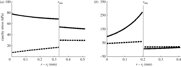
It is well known that tissues grow and remodel in response to altered mechanical loading and these mechanisms appear to be aimed at restoring the local mechanical environment to a homeostatic state of stress (and/or strain). Whereas studies on native tissues suggest that the homeostatic circumferential and axial stresses are 50–150 kPa, the homeostatic stresses for TEVM, TEVA and TEVMA are not yet known. One advantage to understanding the stress distribution across the vascular wall is the knowledge of local mechanical influences on cellular responses. The predicted circumferential and axial stress in the media and adventitia of a TEVMA at 100 mmHg at an axial stretch of λz = 1.1 were  kPa,
kPa,  kPa,
kPa,  kPa, and
  kPa (figure 8b), which are considerably different when compared with the wall stresses of a human coronary artery as predicted by ([22]; figure 8a). The stress distribution in both the circumferential and axial directions across the native vasculature is relatively uniform compared with the large gradient seen in the media layer of the TEVMA. Indeed, these results suggest that following implant, the TEVMA may experience significant stress-mediated growth and remodelling. For example, large stresses predicted in the media could result in significant local growth (or atrophy) and even IH. Thus, although the overall biomechanical indicators such as compliance and axial force are similar between native coronary arteries and TEVMA, if the local mechanical environment deviates significantly from the homeostatic mechanical environment, maladaptive remodelling may ensue. For this reason, we submit that identification of a predictive constitutive model is critical to conduct design analysis that not only matches the global biomechanical response parameters (e.g. compliance), but also matches the local mechanical environment (i.e. local stresses) to minimize maladaptive remodelling. Such analysis can be used to motivate novel fabrication strategies to achieve reasonable matches to both global and local mechanical targets. Note that the abrupt change in stress at the media–adventitia interface is due to the step-wise change in the material model; in reality, there is a narrow continuous transition between the stresses in the media and those in the adventitia.
Figure 8.
Predicted circumferential and axial stresses for a representative coronary artery (a) using the constitutive model and material parameters of Holzapfel et al. [35] and for a TEVMA (b) using the material parameters from table 2 (thick solid line, tθθ; thick dashed line, tzz).
While these models provide good insights into the local mechanical response as well as tissue level mechanics, they are not without limitations. The TEVMA was fully capable of loading beyond an axial stretch of 1.2, however because the TEVM was only capable of being tested to λ = 1.2, the two-layer model cannot be extrapolated to predict the response at higher axial stretches. Moreover, at an axial stretch of 1.2, the circumferential strains that were experienced by the TEVMA are considerably smaller than those experienced by the TEVM alone. Thus, the range of strains that the media-like layer of the TEVMA experienced over the experimental loading was different from the range of strains that the TEVM were exposed to during the same experimental loading. Since the material parameters were determined for the TEVM are only valid over the range of strains experienced by the TEVM, any extrapolation outside the range of strains will result in significant error; this is especially true for the chosen constitutive equation that incorporates exponential functions. The predictive capabilities of the model are quickly lost once strains outside of the tested range are introduced as this leads to negative or extremely large values for pressure and axial force. Therefore, one must use caution when using this model as a tool to predict the material response of the tissue-engineered vasculature.
In summary, our in vitro biomechanical characterization has demonstrated that TEVMA displayed compliance on the same order of magnitude as native vessels when subjected to the same physiological loads. Previous studies have shown that TEVMA do possess the mechanical strength to be used as a viable graft [9,38], but biomechanical properties at physiological loads had not been characterized until now. In order for these vessels to have the greatest chance of patency, their biomechanical properties would ideally match that of the surrounding vasculature. The results of these experiments demonstrate that the biomechanical response of the self-assembly tissue-engineered constructs does not precisely match that of the native vasculature, but we have now developed a model to better understand the effect of different assembly strategies on the biaxial biomechanical response.
Acknowledgements
This work was supported, in part, by the National Institutes of Health (HL-088 156); we are grateful for this support. LG holds a Canadian chair for tissue engineering and stem cell research from CIHR. The authors would like to thank Cindy Perron for her technical assistance.
References
- 1.Thom T., et al. 2006. Heart disease and stroke statistics–2006 update: a report from the American Heart Association Statistics Committee and Stroke Statistics Subcommittee. Circulation 113, e85–e151 10.1161/CIRCULATIONAHA.105.171600 (doi:10.1161/CIRCULATIONAHA.105.171600) [DOI] [PubMed] [Google Scholar]
- 2.L'heureux N., Paquet S., Labbe R., Germain L., Auger F. A. 1998. A completely biological tissue-engineered human blood vessel. FASEB J. 12, 47–56 [DOI] [PubMed] [Google Scholar]
- 3.Nerem R. M., Seliktar D. 2001. Vascular tissue engineering. Annu. Rev. Biomed. Eng. 3, 225–243 10.1146/annurev.bioeng.3.1.225 (doi:10.1146/annurev.bioeng.3.1.225) [DOI] [PubMed] [Google Scholar]
- 4.Guilak F., Butler D. L., Goldstein S. A., Mooney D. J. 2003. Functional tissue engineering, pp. 258–267 New York, NY: Springer [Google Scholar]
- 5.Isenberg B. C., Williams C., Tranquillo R. T. 2006. Small-diameter artificial arteries engineered in vitro. Circ. Res. 98, 25–35 10.1161/01.RES.0000196867.12470.84 (doi:10.1161/01.RES.0000196867.12470.84) [DOI] [PubMed] [Google Scholar]
- 6.Weinberg C. B., Bell E. 1986. A blood vessel model constructed from collagen and cultured vascular cells. Science 231, 397–400 10.1126/science.2934816 (doi:10.1126/science.2934816) [DOI] [PubMed] [Google Scholar]
- 7.Seliktar D., Nerem R. M., Galis Z. S. 2001. The role of matrix metalloproteinase-2 in the remodeling of cell-seeded vascular constructs subjected to cyclic strain. Ann. Biomed. Eng. 29, 923–934 10.1114/1.1415522 (doi:10.1114/1.1415522) [DOI] [PubMed] [Google Scholar]
- 8.Niklason L. E., Gao J., Abbott W. M., Hirschi K. K., Houser S., Marini R., Langer R. 1999. Functional arteries grown in vitro. Science 284, 489–493 10.1126/science.284.5413.489 (doi:10.1126/science.284.5413.489) [DOI] [PubMed] [Google Scholar]
- 9.L'heureux N., et al. 2006. Human tissue-engineered blood vessels for adult arterial revascularization. Nat. Med. 12, 361–365 10.1038/nm1364 (doi:10.1038/nm1364) [DOI] [PMC free article] [PubMed] [Google Scholar]
- 10.L'heureux N., Stoclet J. C., Auger F. A., Lagaud G. J., Germain L., Andriantsitohaina R. 2001. A human tissue-engineered vascular media: a new model for pharmacological studies of contractile responses. FASEB J. 15, 515–524 10.1096/fj.00-0283com (doi:10.1096/fj.00-0283com) [DOI] [PubMed] [Google Scholar]
- 11.Grenier G., et al. 2005. Tissue reorganization in response to mechanical load increases functionality. Tissue Eng. 11, 90–100 10.1089/ten.2005.11.90 (doi:10.1089/ten.2005.11.90) [DOI] [PubMed] [Google Scholar]
- 12.Grenier G., Remy-Zolghadri M., Bergeron F., Guignard R., Baker K., Labbe R., Auger F. A., Germain L. 2006. Mechanical loading modulates the differentiation state of vascular smooth muscle cells. Tissue Eng. 12, 3159–3170 10.1089/ten.2006.12.3159 (doi:10.1089/ten.2006.12.3159) [DOI] [PubMed] [Google Scholar]
- 13.Laflamme K., Roberge C. J., Labonte J., Pouliot S., D'orleans-Juste P., Auger F. A., Germain L. 2005. Tissue-engineered human vascular media with a functional endothelin system. Circulation 111, 459–464 10.1161/01.CIR.0000153850.53419.50 (doi:10.1161/01.CIR.0000153850.53419.50) [DOI] [PubMed] [Google Scholar]
- 14.Laflamme K., et al. 2006. Adventitia contribution in vascular tone: insights from adventitia-derived cells in a tissue-engineered human blood vessel. FASEB J. 20, 1245–1247 10.1096/fj.05-4702fje (doi:10.1096/fj.05-4702fje) [DOI] [PubMed] [Google Scholar]
- 15.Laflamme K., Roberge C. J., Pouliot S., D'orleans-Juste P., Auger F. A., Germain L. 2006. Tissue-engineered human vascular media produced in vitro by the self-assembly approach present functional properties similar to those of their native blood vessels. Tissue Eng. 12, 2275–2281 10.1089/ten.2006.12.2275 (doi:10.1089/ten.2006.12.2275) [DOI] [PubMed] [Google Scholar]
- 16.Diebolt M., Laflamme K., Labbe R., Auger F. A., Germain L., Andriantsitohaina R. 2007. Polyphenols modulate calcium-independent mechanisms in human arterial tissue-engineered vascular media. J. Vasc. Surg. 46, 764–772 10.1016/j.jvs.2007.05.031 (doi:10.1016/j.jvs.2007.05.031) [DOI] [PubMed] [Google Scholar]
- 17.Remy-Zolghadri M., Laganiere J., Oligny J. F., Germain L., Auger F. A. 2004. Endothelium properties of a tissue-engineered blood vessel for small-diameter vascular reconstruction. J. Vasc. Surg. 39, 613–620 10.1016/j.jvs.2003.08.007 (doi:10.1016/j.jvs.2003.08.007) [DOI] [PubMed] [Google Scholar]
- 18.Zaucha M. T., Raykin J., Wan W., Gauvin R., Auger F. A., Germain L., Michaels T. E., Gleason R. 2009. A novel cylindrical biaxial computer controlled bioreactor and biomechanical testing device for vascular tissue engineering. Tissue Eng. Part A 15, 3331–3340 10.1089/ten.tea.2008.0369 (doi:10.1089/ten.tea.2008.0369) [DOI] [PMC free article] [PubMed] [Google Scholar]
- 19.Baek S., Gleason R. L., Rajagopal K. R., Humphrey J. D. 2007. Theory of small on large: potential utility in computations of fluid–solid interactions in arteries. Comput. Meth. Appl. Mech. Eng. 196, 3070–3078 10.1016/j.cma.2006.06.018 (doi:10.1016/j.cma.2006.06.018) [DOI] [Google Scholar]
- 20.Gauvin R., Ahsan T., Larouche D., Levesque P., Dube J., Auger F. A., Nerem R. M., Germain L. 2010. A novel single-step self-assembly approach for the fabrication of tissue-engineered vascular constructs. Tissue Eng. Part A 16, 1737–1747 [DOI] [PubMed] [Google Scholar]
- 21.Rachev A. 1997. Theoretical study of the effect of stress-dependent remodeling on arterial geometry under hypertensive conditions. J. Biomech. 30, 819–827 10.1016/S0021-9290(97)00032-8 (doi:10.1016/S0021-9290(97)00032-8) [DOI] [PubMed] [Google Scholar]
- 22.Holzapfel G. A., Gasser T. C., Ogden R. W. 2000. A new constitutive framework for arterial wall mechanics and a comparative study of material models. J. Elasticity 61, 1–48 10.1023/A:1010835316564 (doi:10.1023/A:1010835316564) [DOI] [Google Scholar]
- 23.Walden R., L'italien G. J., Megerman J., Abbott W. M. 1980. Matched elastic properties and successful arterial grafting. Arch. Surg. 115, 1166–1169 [DOI] [PubMed] [Google Scholar]
- 24.Jackson Z. S., Gotlieb A. I., Langille B. L. 2002. Wall tissue remodeling regulates longitudinal tension in arteries. Circ. Res. 90, 918–925 10.1161/01.RES.0000016481.87703.CC (doi:10.1161/01.RES.0000016481.87703.CC) [DOI] [PubMed] [Google Scholar]
- 25.Abbott W. M., Megerman J., Hasson J. E., L'italien G., Warnock D. F. 1987. Effect of compliance mismatch on vascular graft patency. J. Vasc. Surg. 5, 376–382 10.1067/mva.1987.avs0050376 (doi:10.1067/mva.1987.avs0050376) [DOI] [PubMed] [Google Scholar]
- 26.Bassiouny H., White S., Glagov S., Choi E., Giddens D., Zarins C. 1992. Anastomotic intimal hyperplasia: mechanical injury or flow induced. J. Vasc. Surg. 15, 708. [DOI] [PubMed] [Google Scholar]
- 27.Trubel W., Schima H., Moritz A., Raderer F., Windisch A., Ullrich R., Windberger U., Losert U., Polterauer P. 1995. Compliance mismatch and formation of distal anastomotic intimal hyperplasia in externally stiffened and lumen-adapted venous grafts. Eur. J. Vasc. Endovasc. Surg. 10, 415–423 10.1016/S1078-5884(05)80163-7 (doi:10.1016/S1078-5884(05)80163-7) [DOI] [PubMed] [Google Scholar]
- 28.Ballyk P. D., Walsh C., Butany J., Ojha M. 1998. Compliance mismatch may promote graft-artery intimal hyperplasia by altering suture-line stresses. J. Biomech. 31, 229–237 10.1016/S0197-3975(97)00111-5 (doi:10.1016/S0197-3975(97)00111-5) [DOI] [PubMed] [Google Scholar]
- 29.Matsumoto T., Hayashi K. 1996. Stress and strain distribution in hypertensive and normotensive rat aorta considering residual strain. J. Biomech. Eng. 118, 62–73 10.1115/1.2795947 (doi:10.1115/1.2795947) [DOI] [PubMed] [Google Scholar]
- 30.Gow B. S., Schonfeld D., Patel D. J. 1974. The dynamic elastic properties of the canine left circumflex coronary artery. J. Biomech. 7, 389–395 10.1016/0021-9290(74)90001-3 (doi:10.1016/0021-9290(74)90001-3) [DOI] [PubMed] [Google Scholar]
- 31.Gow B. S., Hadfield C. D. 1979. The elasticity of canine and human coronary arteries with reference to postmortem changes. Circ. Res. 45, 588–594 [DOI] [PubMed] [Google Scholar]
- 32.Hayashi K., Igarashi Y., Takamizawa K. 1986. New approaches in cardiac mechanics (ed. Kazuo), pp. 285–294 Philadelphia, PA: Taylor & Francis [Google Scholar]
- 33.Purinia B. A., Kas'ianov V. A. 1977. Biomechanical porperties of the human coronary arteries. Kardiologiia 17, 108–111 [PubMed] [Google Scholar]
- 34.Purinia B. A., Kas'ianov V. A., Ozolanta I., Mungalov D. 1979. Biomechanical porperties of human coronary arteries and their variation with age. In Proc 2nd National Conf. on Problems of Biomechanics. Riga, Latvia: Zinatie [Google Scholar]
- 35.Holzapfel G. A., Sommer G., Auer M., Regitnig P., Ogden R. W. 2007. Layer-specific 3D residual deformations of human aortas with non-atherosclerotic intimal thickening. Ann. Biomed. Eng. 35, 530–545 10.1007/s10439-006-9252-z (doi:10.1007/s10439-006-9252-z) [DOI] [PubMed] [Google Scholar]
- 36.Asanuma K., Magid R., Johnson C., Nerem R. M., Galis Z. S. 2003. Uniaxial strain upregulates matrix-degrading enzymes produced by human vascular smooth muscle cells. Am. J. Physiol. Heart Circ. Physiol. 284, H1778–H1784 [DOI] [PubMed] [Google Scholar]
- 37.Chuong C. J., Fung Y. C. 1986. On residual stresses in arteries. J. Biomech. Eng. 108, 189–192 10.1115/1.3138600 (doi:10.1115/1.3138600) [DOI] [PubMed] [Google Scholar]
- 38.Konig G., et al. 2009. Mechanical properties of completely autologous human tissue engineered blood vessels compared to human saphenous vein and mammary artery. Biomaterials 30, 1542–1550 10.1016/j.biomaterials.2008.11.011 (doi:10.1016/j.biomaterials.2008.11.011) [DOI] [PMC free article] [PubMed] [Google Scholar]


