Abstract
Patient motion during an MRI exam can result in major degradation of image quality, and is of increasing concern due to the aging population and its associated diseases. This work presents a general strategy for real-time, intra-image compensation of rigid-body motion that is compatible with multiple imaging sequences. Image quality improvements are established for structural brain MRI acquired during volunteer motion. A headband integrated with three active markers is secured to the forehead. Prospective correction is achieved by interleaving a rapid track-and-update module into the imaging sequence. For every repetition of this module, a short tracking pulse-sequence re-measures the marker positions; during head motion, the rigid-body transformation that realigns the markers to their initial positions is fed back to adaptively update the image-plane – maintaining it at a fixed orientation relative to the head – before the next imaging segment of k-space is acquired. In cases of extreme motion, corrupted lines of k-space are rejected and re-acquired with the updated geometry. High precision tracking measurements (0.01 mm) and corrections are accomplished in a temporal resolution (37 ms) suitable for real-time application. The correction package requires minimal additional hardware and is fully integrated into the standard user interface, promoting transferability to clinical practice.
Keywords: motion correction, prospective, real-time, active marker, device tracking, RF-coil, micro-coil, rigid-body, motion artifact
INTRODUCTION
Patient movement is a fundamental problem in virtually all in vivo MR applications. Motion induces local field variations, causes erroneous positional encoding of k-space data, and corrupts the spin-excitation history between slices; these phenomena manifest in image-space as mis-registrations, blurring, and ghosting. Even a few millimeters of movement during scanning can produce severe artifacts in reconstructed data, rendering images unusable. Often, it is subject populations with the highest potential diagnostic benefit where the utility of MRI is curtailed by motion artifacts. In a study of seventeen patients with frontoparietal tumors, data from five had to be rejected due to gross motion artifacts (1). Even amongst a healthy elderly population, our experience suggests that significant artifacts may appear in 10–20% of high resolution structural brain scans; typically used for diagnostic and morphological analysis, such scans are especially prone to motion artifact due to their longer duration. To address these concerns, a motion correction strategy for brain MRI is presented.
The fact that the head is a rigid-body (to a very close approximation) allows an arbitrary motion to be described by six degrees-of-freedom (6-DOF) – three rotations about a 3D orthogonal coordinate-system, and three translations. Retrospective motion compensation methods, such as those used to co-register multiple image volumes in functional MRI (fMRI) studies, are well established. The most popular algorithms (2) determine the 6-DOF via minimization of a least-squares cost function and only correct for inter-image motion. Retrospective correction involves interpolation, which can cause image blurring, and is further limited by its inability to fully correct for the influences of through-plane motion on local spin-history.
In contrast, prospective strategies compensate for motion in the acquisition stage by keeping the image-plane at a fixed orientation relative to the patient’s head during the scan; thus the need for interpolation is eliminated, and the volume’s spin-history maintained. Several prospective correction techniques for brain MRI have been proposed, each using different reference data to solve for the 6-DOF. An image-based approach known as PACE (3) is able to correct for inter-image motion only, such as between image volumes in an EPI time series. An extension of the original linear navigator concept (4), 3D-navigator methods acquire extra data along various 3D k-space trajectories to estimate the 6-DOF. A spherical navigator (SNAV) (5–8) samples a spherical shell of points, and compares them to a reference by 3D registration of their magnitudes; PACE and SNAVs, however, require relatively long acquisition and registration calculation times (> 2 s per iteration), limiting their usefulness in real-time applications. For improved temporal resolution, cloverleaf navigators (9) trace an abbreviated 3D k-space trajectory; motion is detected by comparing each cloverleaf acquisition to a 12 s reference map acquired before the start of the scan during which the patient must remain motionless. A technique related to navigators, PROPELLER (10) acquires rotating “blades” of k-space where a center circular region is sampled by each blade; information in this region is then used to estimate motion between blades. Implemented as a 2D, retrospective technique, it performs in-plane motion corrections but is limited to only rejecting potential through-plane data.
Alternatively, external reflective markers attached to the subject have been used to track head motion by infrared video cameras (11–15). This requires extensive hardware additions, as well as appropriate synchronization and data transfer between optical system and scanner. A cross-calibration procedure is needed to determine the coordinate transform between camera-space (where positions are tracked) and magnet-space (where image-plane orientation is defined), an initial setup procedure requiring ~ 30 min (14). Further, direct line of sight is required between cameras and markers, so marker mounting to the head becomes problematic – this is currently achieved by affixing markers to a patient-customized dental cast (14).
The method described here uses real-time tracking of multiple active markers to provide the 6-DOF information necessary for prospective correction. Monitoring the position of micro RF-coil “active markers” using magnetic resonance was first introduced in 1986 (16), and later developed as a means of actively tracking the tip of a catheter or surgical tool during MR-guided interventional procedures (17–21). Marker-based techniques have also been combined with navigator echoes (22) and non-Cartesian k-space sampling (23,24) for retrospective motion correction. Proof-of-principle in prospective correction applications was demonstrated in an “offline” inter-image update scheme (25); motion was introduced between complete slice acquisitions, and the tracking system activated to realign the scan-plane geometry, resulting in well registered slices of the same imaged section before and after motion. Recent work by Krueger et al. presented the first use of active markers for real-time motion correction (26), with preliminary results showing image quality improvements in moving phantoms (27).
The current work represents the full development of a complete prospective, real-time compensation package capable of robustly handling any arbitrary rigid-body motion. The simple geometry of the active marker device minimizes correction times, while providing excellent tracking accuracy. A routine that dynamically updates the image-plane orientation is interleaved into the imaging sequence, allowing for intra-image motion compensation – between single or multiple lines of k-space – during the acquisition of a single volume. The general correction strategy can be flexibly incorporated into multiple imaging sequences, promoting its utility in a variety of MR applications. The implementation and results presented here demonstrate its application in 2D/3D structural brain scans.
METHODS
Overview
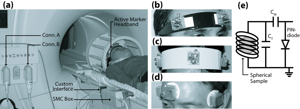
The setup for a motion corrected brain exam is shown in Fig. 1a. A headband integrated with three active markers is secured to the forehead of a volunteer, maintaining a fixed location relative to the head so that any head movement is reflected in the markers. Three points in 3D-space are sufficient to uniquely solve for the 6-DOF transform that fully describes any arbitrary rigid-body motion. This transformation is fed back to dynamically adjust the image-plane, keeping it at a fixed orientation relative to the head, and thus prospectively compensating for the motion.
Fig. 1.
(a) Hardware setup for motion correction package. Multi-channel MR system allows dual-coil option for imaging using a standard bird-cage coil (Conn. A), and tracking using the active marker headband (Conn. B). Active markers communicate with MR system via SMC circuitry, which is mounted to the side of the scanner bed. (b–d) Prototype headband designs include hairband, velcro-strap, and electrode-style. Design (b) was used for all in vivo results presented. (e) Active marker schematic, consisting of a micro-coil wrapped around a spherical sample, with appropriate tuning and matching capacitance. Resonant circuit is actively detuned during RF-transmit via PIN-diode and SMC-controlled decoupling current.
Figure 2 outlines the modifications to a general image acquisition loop, with a focus on structural imaging sequences, that are needed to perform this in real-time. At scan start, a reference tracking module measures the initial positions of all active markers. In the following iterative loop, tracking and geometry update modules are interleaved into the imaging sequence until all k-space is acquired. For scans with a pre-pulse, e.g. inversion, saturation, magnetization preparation, this is performed first. Next, the tracking module is performed to re-measure marker locations after any arbitrary motion. In the geometry update module, current marker positions are compared with their initial reference positions, and the 6-DOF rigid-body transform determined that realigns the markers; this transform is then used to adaptively update the image-plane orientation. The tracking module is performed immediately before the imaging module, and after any (typically long) magnetization preparation delay, in order to minimize the time between geometry update and imaging. In the rejection module, if the displacement, i.e. “motion” in Fig. 2, between the current and previous tracking measurements (defined as the distance measured from the outermost edge of the imaging FOV) is greater than a user-defined rejection “threshold”, then the most recently acquired k-space data is discarded and the subsequent imaging module re-acquires the rejected k-space with updated geometry. If, however, motion is within the threshold limit, then the data is accepted and the following imaging module acquires the next segment of k-space as usual. Depending on the imaging sequence, the imaging module could acquire a single k-space phase-encode (spin-echo (SE) or gradient-echo (GE)), or a number of phase-encodes equal to the echo train length (ETL) for segmented k-space acquisitions (fast SE/GE (FSE/FGE)). The tracking and update frequency is controlled by setting “interval”, the number of imaging modules acquired between tracking modules. Once the motion corrected scan is complete, images are conventionally reconstructed on the scanner, and immediately available for viewing. For each iteration, the total time for all tracking acquisitions, calculations, and updates (dashed boundary in Fig. 2) is several tens of milliseconds, specifically 37 ms for the images presented here.
Fig. 2.
Flowchart of motion tracking and prospective correction strategy – consisting of tracking, geometry update, and rejection modules (white boxes) – interleaved into a generic imaging pulse-sequence (shaded boxes). The algorithm’s primary functionality is enclosed by the dashed boundary.
All experiments were performed on a 1.5T Philips Achieva (Philips Medical Systems, Best, The Netherlands). The tracking pulse-sequence and modifications to the imaging sequence’s run-time execution were programmed in Philips Pulse Programming Environment, and a software patch was generated that seamlessly integrates all prospective correction options into the standard Philips graphical user interface (GUI). Software patch and active marker headband comprise the complete prospective correction package – no other additional hardware or software is required for acquisition or post-processing other than that available on the standard clinical Philips MR system.
Active Micro-Coil Tracking Device
Each active marker (Fig. 1e) is a glass sphere (3.25 mm internal diameter) filled with 10 mM Gd-doped water solution. The spherical symmetry minimizes orientation-dependence of the sample, and its short T1 allows full signal recovery in the presence of rapid tracking and imaging RF-pulse excitations. A miniature RF receive-coil with appropriate capacitors for a tuned and matched network surrounds each sphere. The resonance circuit is enclosed in a 25×25×17 mm acrylic casing with an RF-shielded base to prevent the micro-coil from picking up signals from the patient. Each marker is attached via transmission line to a custom interface box, which is connected to a Synergy Multi-Connect box (Philips Medical Systems, Best, NL, by IGC Medical Advances) provided for third-party coils (Fig. 1a). The SMC box connects to a standard frontend coil connector. The multi-channel MR system allows for simultaneous imaging with any standard Philips coil, and position tracking via our custom active marker device.
Several headband designs were investigated to firmly affix the markers to the head – including a semi-flexible plastic hairband, velcro-strap, and ECG-style electrodes (Fig. 1b–d). The setup of Fig. 1b showed the most promising rigid-body mounting to the head that minimized slippage, and is used for all in vivo results.
Tracking Module
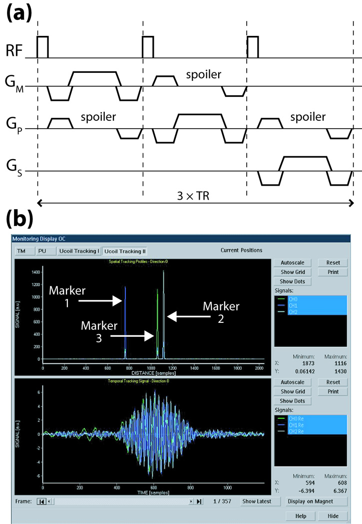
The spherical samples are excited by a weak non-selective RF-pulse (flip-angle = 3°) from the volume coil, in order to minimize effects on imaged spins. This is followed by gradient-echo projection readouts in three orthogonal directions (Fig. 3a), thereby determining the position of each active marker uniquely in 3D-space (17). Tracking sequence and measurements are defined in the image mps-coordinate system (directions m: measurement, p: phase-encode, s: slice-selection). The markers are measured simultaneously, and since the receive channels are independent, the signals from each can be separately and unambiguously identified.
Fig. 3.
(a) Basic tracking pulse-sequence using only positive readout gradients (time = 3×TR). For B0-correction, this sequence is repeated with reversed polarities for each readout (time = 6×TR); positions are then determined by averaging the independently computed locations from the two opposite readouts. (b) Scanner GUI monitoring of tracking profiles in space (upper plot) and time (lower plot) of three active markers after the first projection readout GM. Similar plots are displayed in real-time for all three gradient directions over the scan’s duration.
The time signal received from each micro-coil during one projection readout Gm (Fig. 3b, lower plot) is dominated by the frequency f0 corresponding to its spatial location, r0, given by the linear relationship: r0 = f0•2π/γ/Gm. Fourier transform of each time signal yields its dominant frequency component (Fig. 3b, upper plot), and hence each marker’s position along the projected axis. To refine the marker’s location, a quadratic fit to the intensities of the peak and two surrounding points is made. Since the peak’s signal-to-noise ratio (SNR) is typically > 1000, this yields sub-millimeter resolution of each marker’s position, well below the raw digital resolution. For example, for a sequence-defined tracking digital resolution of 1 mm, the quadratic fit provides resolution of the marker position to ~ 0.01 mm. Although only relative displacement of markers is needed for our tracking algorithm, we also implemented a symmetric gradient readout scheme in order to acquire B0 independent position information (17) that was used to compare with measurements of the marker displacements made by caliper in the following grid validation tests.
The micro-coil’s small radius and RF-shielding ensures most of its received signal originates from its own spherical sample. Spoiler gradients (Fig. 3a) designed to dephase the magnetization in large volumes while preserving signal from the smaller spheres (21) are used to further enhance the spherical sample’s signal relative to any signal from its surroundings.
Run-time execution of the tracking module can be adjusted by GUI selection of tracking interval, rejection option (enable/disable, threshold), and tracking sequence (type, flip-angle, resolution). In the current work, typical values are: interval = 1, threshold = 10 mm, flip-angle = 3°, resolution = 1 mm, and TR = 8.3 ms. The total delay for the tracking module is then = 3×TR + position calculations = 25 ms + 10 ms = 35 ms. Additionally, time and frequency signals of each active marker are displayed in real-time on the scanner console after every tracking shot, if desired, by enabling an external monitoring option (Fig. 3b); this allows visual confirmation of sufficient marker SNR for accurate tracking.
Geometry Update Module
The transformation to correct for rigid-body motion involves 6-DOF – three rotations θm, θp, θs and three translations tm, tp, ts. By placing three active markers in a linearly independent arrangement, i.e. as the vertices of any asymmetric triangle, a unique rigid-body transformation can be identified that realigns the triangles. As long as this triangular marker arrangement moves with the anatomy, we can apply this transformation to the image-plane orientation to compensate for motion.
Let the set X = {x1 , x2 , x3 } contain the three active marker position vectors measured by the reference tracking module (see Fig. 2), and Y = {y1, y2, y3 } the positions re-measured after some arbitrary motion. Let R be the 3×3 rotation matrix defined by θm, θp, θs, and t = [tm, tp, ts]T the 3×1 translation vector. Minimizing the following least-squares cost function:
| [1] |
results in the rotation R and translation t that realigns Y onto X. The following closed-form solution presented by Umeyama (28), using the singular value decomposition (SVD) of a covariance matrix of the data, is implemented in this module. We define:
| [2] |
| [3] |
| [4] |
| [5] |
μx and μy are 3×1 mean vectors of X and Y, respectively, while Σxy is a 3×3 covariance matrix of X and Y. The optimum solution is given in Eqs. [6], [7]. For a detailed proof, see Umeyama (28).
| [6] |
| [7] |
The transform defined by R and t is used to update the initial image-plane orientation by modifying the relevant RF, gradient, and data acquisition attributes in the imaging pulse-sequence. The simple geometry of the problem, essentially a 3-point 3D registration calculation, results in a total time of only 2 ms for all geometry calculations and updates in this module.
Image Quality Metric
To quantitatively assess image quality, a metric is developed that is based on the signal power in the image at high spatial frequencies. High k-space frequencies contain information with respect to small-scale spatial variations such as edges, while low frequencies correspond to homogeneous regions of uniform intensity in image-space. Motion tends to cause image blur and loss of edge definition, which is reflected by a decrease in energy at high frequencies.
A quality metric Q is defined that quantifies degradation in edge sharpness. Given a volume V, its power spectrum is generated from the Fourier transform of its magnitude images. A cutoff frequency ωc is chosen to delineate between edged vs. smooth image characteristics. High frequency power spectra above ωc is integrated over all slices, and normalized to the volume’s total power, to yield PV. For a reference volume, the same calculations are performed to obtain Pref. We then define Q = PV/Pref×100. Image quality Q is thus a measure of the high frequency power contained in V, expressed as a percentage relative to a reference volume; to best compare improvements in image quality allowed by motion correction, uncompensated scans with the volunteer at rest were chosen as reference volumes. A range of ωc was tested between 0.02 to 0.1 cycles/mm. Integration above ωc = 0.02 cycles/mm yields Q’s sensitive to changes in spatial objects below 25 mm, while ωc = 0.1 cycles/mm reflects spatial variations below 5 mm. Analysis was performed using Matlab (Mathworks, Natick, MA, USA).
Active Marker Validation
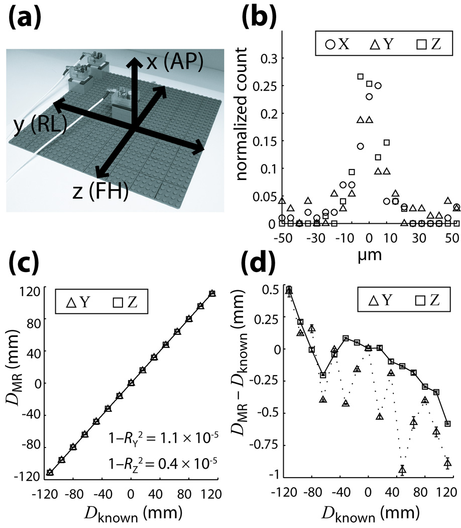
The quality of active marker position measurements was evaluated using standard LEGO pieces to provide a framework for accurate and reproducible movement since they possess excellent machined tolerance (< 2 µm) (29). A planar 260×260 mm (32×32 stud) LEGO base-plate was mounted to a rigid board to avoid flexing, and secured to the scanner bed in a coronal orientation; using the optical positioning laser, the center of the grid was positioned at the magnet isocenter and aligned with the y-z gradient axes (Fig. 4a). For these experiments, we refer to the xyz-coordinate system since we wish to test the physical gradient directions.
Fig. 4.
(a) Setup of grid for validation tests showing its orientation relative to gradient and patient axes. (b) Reproducibility of MR position measurements along the x,y,z gradient axes, illustrated as a histogram distribution of the deviation of each measurement from its corresponding mean. (c) Accuracy of measurements is displayed by comparing MR and caliper (known) measured distances along the y and z axes. Least-squares linear regression fits result in high correlation coefficients RY and RZ for both directions. (d) Measurement error between MR and caliper values as a function of distance. Error bars in (c,d) are the standard deviations of MR measurements at each position, reflecting the high reproducibility in (b). All curves are plotted with B0-corrected data; plots using positive readout gradients are similar in nature.
An active marker was mounted to a 4×4 stud mobile base, which could be precisely and securely affixed to any point on the LEGO grid via the stud-and-tube coupling mechanism. An active marker was thus moved in 16 mm increments along the y and z axes co-planar to the LEGO grid, and 15 positions measured along each axis; for measurements along the x-axis, the mobile base was placed at the center of the grid and “built up” as a tower in the vertical direction in 19 mm increments and 10 positions measured. Measurements (x = 0 to 171 mm, y = z = −112 to 112 mm) cover the full range of motions typically possible within the confines of a standard bird-cage head-coil. The B0-corrected tracking sequence was run five times at each position, resulting in a set of measurements to be used for evaluation of tracking accuracy and reproducibility along the three gradient axes.
In Vivo Tests
A standard bird-cage coil was used to acquire brain MRI (Fig. 1a) in the presence of head motion. Experiments were designed to validate effectiveness of the correction strategy under a variety of imaging parameters and motion conditions. All experiments with human subjects were in accordance with local IRB regulations and informed consent was obtained before each exam.
Three cases were investigated: in-plane motion and through-plane motion using multi-slice gradient-echo (2D-GE), and 3D magnetization prepared rapid acquired gradient-echo (3D-MPRAGE) to establish the correction scheme’s effectiveness in a more complex sequence. For each case, a volunteer was trained to reproduce three types of motions: a baseline “at rest” position containing only unconscious physiological motion, a continuous, smooth ±5–10° left-right head-shake, and an intermittent, but abrupt ±5–10° left-right head-jerk. Motions were performed throughout the entire scan. For each motion, the scan was performed twice – with prospective correction ON and OFF – resulting in a total of six scans per case. For scans with correction OFF, all tracking and geometry calculations were performed and logged – but not applied to update the image-plane – in order to verify reproducibility of volunteer motion within each matching pair of motion conditions.
For the two multi-slice cases, 2D-GE scans (TE/TR = 2.4/185 ms, flip-angle = 90°, FOV = 250 mm2, in-plane resolution = 1 mm2, slices = 3, thickness/gap = 5/3 mm, number of signal averages = 2, scan time = 3:45) were performed with line-by-line prospective correction. In one case, axial slices were acquired so the left-right headshake would simulate in-plane motion. In the other case, coronal slices were acquired with the left-right movement now inducing through-plane motion. For the 3D-MPRAGE case, which incorporates a 180° inversion pre-pulse for T1-weighting with a fast, segmented, volumetric k-space acquisition (TE/TR/TI/shot interval = 4/8.3/1000/1500 ms, flip-angle = 8°, FOV = 240×240×100 mm, voxel size = 1.25×1.25×2 mm, slices = 50, ETL = 48, scan time = 6:50), track-and-update modules were interleaved every 48 k-space phase-encodes (~ 400 ms of image data acquisition). Scan durations were increased due to extensive real-time logging of tracking information required at this developmental stage of testing; with logging disabled, scan times reduce to 2:27 and 6:33 for the 2D-GE and 3D-MPRAGE sequences, respectively. The original scan times of each sequence with prospective correction entirely disabled are 1:33 and 6:25.
RESULTS
Active Marker Validation
The data gathered from grid tests was used to assess reproducibility and accuracy of the active marker tracking scheme. For all positions tested on the grid, the distance from each MR measurement (N = 5 for each position) to a reference point at the center of the grid (within 30 mm of the magnet isocenter to minimize measurement distortions) was calculated. The resulting set of mean MR-measured distances at each position DMR, were compared with corresponding distances Dknown measured by digital caliper (Mitutoyo Corp., Japan) at the same marker positions.
To illustrate reproducibility of the MR measurements at each grid position, histograms of the deviation of each measurement from its corresponding mean value DMR at that position are plotted for each gradient direction (Fig. 4b). All three directions depict a Gaussian distribution with FWHM < 0.01 mm, demonstrating high measurement precision which agrees well with our estimate of the quadratic fit resolution based on peak SNR.
Accuracy with respect to caliper measured distances Dknown is shown in Fig. 4c and 4d. Figure 4c plots DMR vs. Dknown for the y and z gradient directions; least-squares linear regression shows high correlation between measurements in both directions. To better visualize the small errors, Fig. 4d plots DMR − Dknown vs. Dknown. For tracking with B0-correction, overall localization errors (mm, mean ± SD) were 0.30 ± 0.40 and 0.07 ± 0.24 along the y and z axis, respectively; using only positive readout gradients, errors observed were 0.26 ± 0.43 and 0.07 ± 0.28 along the y and z axis. The minimal difference between measurement methods may be attributed to a well-shimmed B0 field. Due to similarity of the physical x and y gradients, behavior in the x direction was not investigated further.
In Vivo Tests
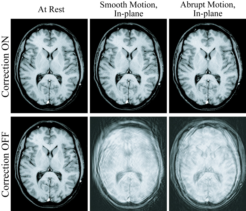
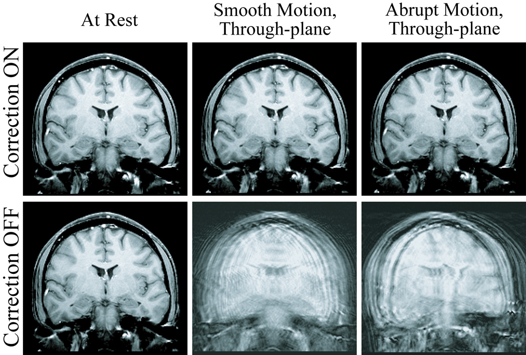
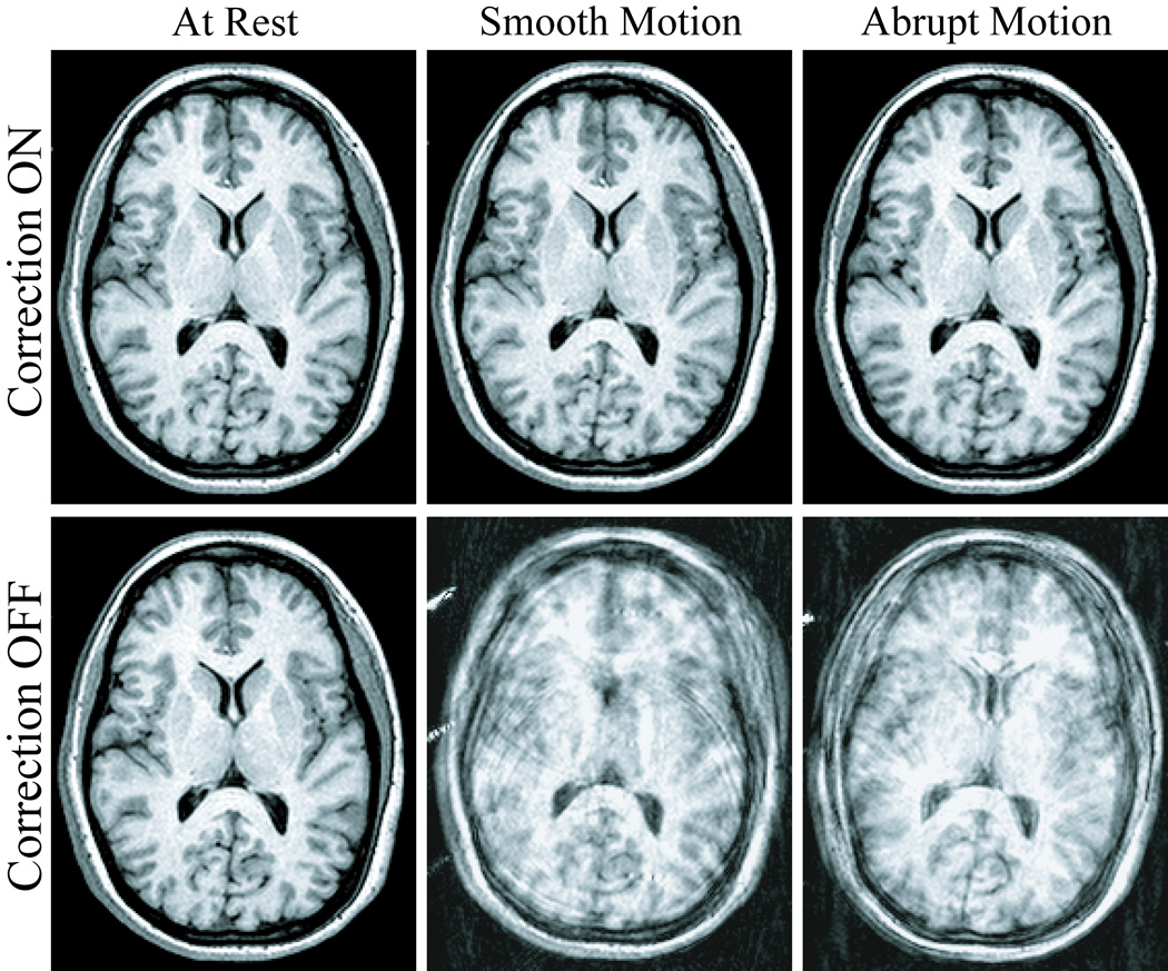
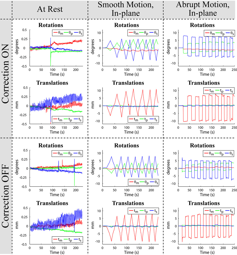
Exemplary slices from the six scans acquired for each of the three human volunteer cases are displayed in Fig. 5, Fig. 7, and Fig. 8. Images in the first row were acquired with correction, and images in the second row without correction. Pairs of images in every column were acquired in the presence of similar motion, namely with the volunteer at rest (first column), and reproducing continuous-smooth (second column), and intermittent-abrupt (third column) left-right headshakes. Comparing matching pairs of scans within each column illustrates the dramatic improvement achieved with motion compensation; for all compensated images, virtually perfect correction is achieved with respect to the reference scan (second row, first column), with no observable degradation in image quality. Figure 6 shows the corresponding motion plots over time for each scan in Fig. 5, where the plotted 6-DOF transform parameters are derived from active marker locations tracked in real-time. From Fig. 6, the nature of the two types of intentional motion is apparent, and is well reproduced by the volunteer between matching pairs of scans. Tracking plots for the scans in Fig. 7 and Fig. 8 reflected similarly well reproduced volunteer movements within each pair of motion conditions and are not shown. Average motion rejection rates over all cases for at rest, smooth, and abrupt motion scans are 0%, 0%, and 9%, respectively; the 9% of data rejected in the abrupt cases correlates with the timing of the intermittent head jerks.
Fig. 5.
Six different 2D-GE axial scans, demonstrating improvements in image quality for the in-plane motion case. The volunteer is at rest (first column), and performing smooth (second column) and abrupt (third column) deliberate left-right head-shakes; two scans were acquired for each motion, with prospective correction turned ON (first row) and OFF (second row). The movements were well reproduced by the volunteer within each pair of acquisitions, as demonstrated by the corresponding tracking plots in Fig. 6.
Fig. 7.
Six different 2D-GE coronal scans, illustrating improvements in image quality for the through-plane motion case. The volunteer is at rest (first column), and performing smooth (second column) and abrupt (third column) deliberate left-right head-shakes, similar to those shown in Fig. 6; two scans were acquired for each motion, with prospective correction turned ON (first row) and OFF (second row).
Fig. 8.
Six different 3D-MPRAGE scans, demonstrating the flexibility of the prospective correction strategy in more complex imaging sequences. The volunteer is at rest (first column), and performing smooth (second column) and abrupt (third column) deliberate left-right head-shakes throughout the entire volumetric acquisition; two scans were acquired for each motion, with correction ON (first row) and OFF (second row).
Fig. 6.
Active marker motion tracking information for the six scans in Fig. 5, plotted as measured rotations (θm, θp, θs) and translations (tm, tp, ts) vs. time. For ease of reference, the layout of the plots above is identical to the layout of the images they correspond to in Fig. 5. The nature of the smooth-continuous (second column) and abrupt-intermittent (third column) head-shakes is apparent, and well reproduced by the volunteer during prospective correction ON (first row) and OFF (second row) acquisitions. The time axis covers the full scan duration, showing that motion occurred throughout the entire multi-slice acquisition.
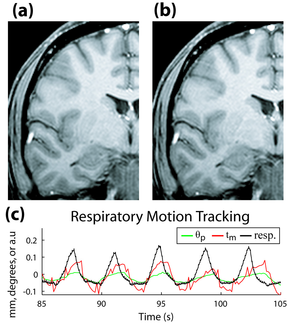
Figure 9 shows the potential advantage of prospective correction in situations without any intentional subject motion. Two 2D-GE coronal scans with the volunteer at rest are shown, with (Fig. 9a), and without (Fig. 9b) correction. The faint ringing artifact in Fig. 9b is no longer visible in Fig. 9a, suggesting compensation for residual physiologically-induced motion. In Fig. 9c, tracking information from the active markers contained a frequency cycle matching the scanner’s respiratory bellows monitor, confirming that the dominant effect on the resting image was due to breathing.
Fig. 9.
(a) 2D-GE coronal image of volunteer at rest with correction ON, and (b) correction OFF. (c) Motion during the scan, measured with active markers (θp in degrees, tm in mm), and respiratory bellows sensor (arbitrary units), illustrating correlation between frequency of motion tracked by markers and respiratory cycle of volunteer.
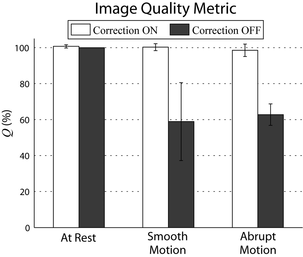
For each scan, Q was calculated over a range of cutoff frequencies. Figure 10 summarizes the results for a spatial cutoff < 12 mm. Average Q of all motion corrected scans is > 98%, near perfect correction relative to the reference scan; for at rest and smooth motions, average Q > 100%, signifying image quality above what even a well-motivated volunteer can achieve without correction.
Fig. 10.
Comparison of image quality between corrected vs. uncorrected scans using metric Q. For each of the three motions tested, each column represents the average Q over the three volunteer cases, while the error bars are standard deviations between cases. Substantial improvement in Q between corrected and uncorrected scans can be seen for both types of deliberate motions. Q’s were generated using ωc = 0.04 cycles/mm, sensitive to spatial variations < 12 mm. Similar results were found for the range of ωc tested. Note that changes in Q reflect relative changes in the high frequency power band, rather than total volume power.
DISCUSSION AND CONCLUSIONS
This work demonstrates utilization of active markers in a fully integrated, real-time motion tracking and correction package for brain MRI. A general strategy is presented for interleaving a short track-and-update module into multiple imaging sequences. The method is successfully implemented in 2D-GE and 3D-MPRAGE scans, with prospective correction applied before every k-space phase-encode or segmented acquisition, respectively.
The most common motions during scanning – slow, continuous motions, and fast but intermittent jerks – were evaluated and robustly handled by the compensation strategy. The raw temporal tracking resolution was sufficient to handle moderate, continuous motions. For rapid motions, too fast for tracking to follow, corrupted k-space data was rejected and re-acquired after the motion was completed. The strategy did equally well to correct both in-plane and through-plane motions. A quantitative image quality assessment showed substantial improvement for all cases of intentional motion, confirming positive visual inspection.
Even with compliant, healthy volunteers, scans where they are instructed to remain motionless can contain sufficient physiological motion to cause faint ringing artifact, and decrease in edge definition. This artifact is no longer visible in corrected images, suggesting utility in cases where even no extreme motions are present. These improvements will likely become more apparent at higher scan resolutions.
Tracking accuracy compared favorably with absolute accuracies for SNAV (8) and optical (14) schemes ( 0.3 mm and 0.25 mm, respectively). More importantly, measurements were also highly reproducible; this is relevant for motion correction since markers are realigned to a reference position, which requires only relative comparison of marker displacements. This contrasts with catheter tracking where absolute accuracy is crucial. Thus, the basic tracking pulse-sequence using only positive readouts was sufficient to achieve the results presented.
Tracking plus corrections were performed in a time on-par with cloverleaf (9) and optical (14) strategies (18.2 ms and 32 ms, respectively). In our current implementation, the tracking TR was defined by the imaging TR; in principle, optimizing the tracking pulse-sequence by employing the system’s maximum gradient specifications will allow the delay per iteration to be reduced from 37 ms to under 20 ms, while still achieving the same tracking spatial resolution. Additionally, track-and-update modules were directly added to the original imaging sequence, i.e. dead time between TRs was not utilized, which would further reduce total delays.
In the 2D-GE cases with information logging disabled, line-by-line correction increased original scan times by 58%. Since increase in scan time is proportional to tracking frequency, combining intermittent tracking with imaging trajectories less sensitive to motion may be an effective compromise for time-critical studies. For example, tracking can be performed between segmented k-space readouts acquired with a reverse-centric phase-encode ordering scheme; in this manner, the phase-encodes in the segment most sensitive to motion – the high frequency k-space – may be acquired closest to when geometry corrections are applied, followed by the low frequency phase-encodes. This should help retain edge information, while fewer tracking interleaves will minimize scan times. This is demonstrated in the 3D-MPRAGE case, which increased original scan times by only 2%. Applying prospective correction to non-Cartesian trajectories, such as radial and spiral readouts, may further decrease a scan’s motion sensitivity.
The correction package requires minimal additional hardware and can be implemented in any clinical scanner with multi-channel capability, provided that three designated channels are available for tracking. Potential improvements include advancements to the basic headband design presented. Using the micro-coils to transmit the tracking RF-pulse would minimize the tracking sequence’s effects on imaged spins. The size of each marker can be reduced to < 1 cm3(21), facilitating their use with tighter-fitting head coils. Alternative head mounting strategies may be explored, including integration of markers into patient headphones (26); however any strategy must maintain a rigid-body and minimize slippage with the skin. Wireless active markers (30) may also provide improved patient comfort.
The strategy’s versatility lends itself to a wide range of MR applications. Results focused on structural imaging sequences, of particular applicability to diagnostic and morphological studies. The technique is also compatible with EPI-based protocols such as fMRI, and arterial spin-labeling (ASL). Currently, these studies almost exclusively employ retrospective image-based correction. Prospective compensation in fMRI may be realized by interleaving track-and-update modules between volume or slice acquisitions in the EPI time series. For a typical fMRI experiment (TR = 2 s, 25 slices), inter-volume updates of 20 ms will increase total scan time by 1%. Updates between every slice will increase times by 25%; in studies where this delay is prohibitive, tracking frequency may be decreased, e.g. updating every 5 slices will increase times by 5%. For ASL, corrections incorporated into the transit time between labeling and imaging will not incur any time penalty. In brain spectroscopy, updates may be inserted between sampling averages or, for chemical shift imaging, between spatial phase-encodes. Application of the full motion correction strategy is largely constrained to the head because of the rigid-body assumption. For non rigid-body applications, the rejection module can be used as a gating mechanism, providing a competitive alternative to linear navigators; for example, in chest or carotid imaging, markers may be placed around the chest or on the Adam’s apple to monitor breathing or swallowing motions, and k-space only acquired when marker positions fall within a certain range. Utility in these applications will be avenues of future investigation.
ACKNOWLEDGEMENTS
We thank the NIH for their funding (grant: R21EB006877), as well as Melanie Kotys, Brian Welch, Cecil Hayes, Robin Goldman, Christina Tosti, and Hamed Mojahed for their support.
List of Symbols
- B0
Italic upper case ‘bee’, subscript roman ‘zero’
- T1
Italic upper case ‘tee’, subscript roman ‘one’
- x0
Italic lower case ‘ex’, subscript roman ‘zero’
- f0
Italic lower case ‘eff’, subscript roman ‘zero’
- π
Greek roman lower case ‘pi’
- γ
Greek roman lower case ‘gamma’
- Gm
Italic upper case ‘jee’, subscript roman lower case ‘em’
- θm, θp, θs
Greek italic lower case ‘theta’, subscript roman lower case ‘em’, ‘pee’, or ‘ess’
- tm, tp, ts
Italic lower case ‘tee’, subscript roman lower case ‘em’, ‘pee’, or ‘ess’
- x1, x2, x3
Bold roman lower case ‘ex’, subscript roman ‘one’, ‘two’, or ‘three’
- y1, y2, y3
Bold roman lower case ‘why’, subscript roman ‘one’, ‘two’, or ‘three’
- μx, μy
Greek bold roman lower case ‘mu’, subscript roman lower case ‘ex’, or ‘why’
- Σxy
Greek bold roman upper case ‘sigma’, subscript roman lower case ‘ex’ and ‘why’
- ωc
Greek italic lower case ‘omega’, subscript roman lower case ‘see’
- Q
Italic upper case ‘kew’
- PV
Italic upper case ‘pee’, subscript roman upper case ‘vee’
- Pref
Italic upper case ‘pee’, subscript roman lower case ‘are’, ‘ee’, ‘ef’
- DMR
Italic upper case ‘dee’, subscript roman upper case ‘em’, ‘are’
- Dknown
Italic upper case ‘dee’, subscript roman lower case ‘known’
- RY
Italic upper case ‘are’, subscript roman upper case ‘why’
- RZ
Italic upper case ‘are’, subscript roman upper case ‘zee’
REFERENCES
- 1.Righini A, de Divitiis O, Prinster A, Spagnoli D, Appollonio I, Bello L, Scifo P, Tomei G, Villani R, Fazio F, Leonardi M. Functional MRI: primary motor cortex localization in patients with brain tumors. Journal of Computer Assisted Tomography. 1996;20(5):702–708. doi: 10.1097/00004728-199609000-00003. [DOI] [PubMed] [Google Scholar]
- 2.Ardekani BA, Bachman AH, Helpern JA. A quantitative comparison of motion detection algorithms in fMRI. Magnetic Resonance Imaging. 2001;19(7):959–963. doi: 10.1016/s0730-725x(01)00418-0. [DOI] [PubMed] [Google Scholar]
- 3.Thesen S, Heid O, Mueller E, Schad LR. Prospective acquisition correction for head motion with image-based tracking for real-time fMRI. Magnetic Resonance in Medicine. 2000;44(3):457–465. doi: 10.1002/1522-2594(200009)44:3<457::aid-mrm17>3.0.co;2-r. [DOI] [PubMed] [Google Scholar]
- 4.Ehman RL, Felmlee JP. Adaptive technique for high-definition MR imaging of moving structures. Radiology. 1989;173(1):255–263. doi: 10.1148/radiology.173.1.2781017. [DOI] [PubMed] [Google Scholar]
- 5.Welch EB, Manduca A, Grimm RC, Ward HA, Jack CR., Jr Spherical navigator echoes for full 3D rigid body motion measurement in MRI. Magnetic Resonance in Medicine. 2002;47(1):32–41. doi: 10.1002/mrm.10012. [DOI] [PubMed] [Google Scholar]
- 6.Petrie DW, Costa AF, Takahashi A, Yen YF, Drangova M. Optimizing spherical navigator echoes for three-dimensional rigid-body motion detection. Magnetic Resonance in Medicine. 2005;53(5):1080–1087. doi: 10.1002/mrm.20445. [DOI] [PubMed] [Google Scholar]
- 7.Wyatt CL, Ari N, Kraft RA. Information Processing in Medical Imaging. Glenwood Springs, CO, USA: 2005. Spherical Navigator Registration Using Harmonic Analysis for Prospective Motion Correction; pp. 738–749. [DOI] [PubMed] [Google Scholar]
- 8.Ari N, Kraft RA. Real-time Motion Detection Algorithms for Spherical Navigator Echoes in Functional MRI. Proceedings of the 14th Annual Meeting of ISMRM; Seattle, WA, USA. 2006. p. 3195. [Google Scholar]
- 9.van der Kouwe AJW, Benner T, Dale AM. Real-time rigid body motion correction and shimming using cloverleaf navigators. Magnetic Resonance in Medicine. 2006;56(5):1019–1032. doi: 10.1002/mrm.21038. [DOI] [PubMed] [Google Scholar]
- 10.Pipe JG. Motion correction with PROPELLER MRI: application to head motion and free-breathing cardiac imaging. Magnetic Resonance in Medicine. 1999;42(5):963–969. doi: 10.1002/(sici)1522-2594(199911)42:5<963::aid-mrm17>3.0.co;2-l. [DOI] [PubMed] [Google Scholar]
- 11.Eviatar H, Schattka B, Sharp JC, Rendell J, Alexander ME. Real Time Head Motion Correction for Functional MRI. Proceedings of the 7th Annual Meeting of ISMRM; Philadelphia, PA, USA. 1999. p. 262. [Google Scholar]
- 12.Tremblay M, Tam F, Graham SJ. Retrospective coregistration of functional magnetic resonance imaging data using external monitoring. Magnetic Resonance in Medicine. 2005;53(1):141–149. doi: 10.1002/mrm.20319. [DOI] [PubMed] [Google Scholar]
- 13.Dold C, Zaitsev M, Speck O, Firle EA, Hennig J, Sakas G. Advantages and Limitations of Prospective Head Motion Compensation for MRI Using an Optical Motion Tracking Device. Academic Radiology. 2006;13(9):1093–1103. doi: 10.1016/j.acra.2006.05.010. [DOI] [PubMed] [Google Scholar]
- 14.Zaitsev M, Dold C, Sakas G, Hennig J, Speck O. Magnetic Resonance Imaging of Freely Moving Objects: Prospective Real-time Motion Correction Using an External Optical Motion Tracking System. NEUROIMAGE. 2006;31(3):1038–1050. doi: 10.1016/j.neuroimage.2006.01.039. [DOI] [PubMed] [Google Scholar]
- 15.Qin L, van Gelderen P, Jin F, Tao Y, Duyn JH. Prospective head movement correction for high resolution MRI using an in-bore optical tracking system. Proceedings of the 15th Annual Meeting of ISMRM; Berlin, Germany. 2007. p. 1828. [DOI] [PMC free article] [PubMed] [Google Scholar]
- 16.Ackerman JL, Offutt MC, Buxton RB, Brady TJ. Rapid 3D Tracking of Small RF Coils. Proceedings of the 5th Annual Meeting of ISMRM; Montreal, QC, Canada. 1986. pp. 1131–1132. [Google Scholar]
- 17.Dumoulin CL, Souza SP, Darrow RD. Real-time position monitoring of invasive devices using magnetic resonance. Magnetic Resonance in Medicine. 1993;29(3):411–415. doi: 10.1002/mrm.1910290322. [DOI] [PubMed] [Google Scholar]
- 18.Zhang Q, Wendt M, Aschoff AJ, Zheng L, Lewin JS, Duerk JL. Active MR guidance of interventional devices with target-navigation. Magnetic Resonance in Medicine. 2000;44(1):56–65. doi: 10.1002/1522-2594(200007)44:1<56::aid-mrm10>3.0.co;2-5. [DOI] [PubMed] [Google Scholar]
- 19.Flask C, Elgort D, Wong E, Shankaranarayanan A, Lewin J, Wendt M, Duerk JL. A method for fast 3D tracking using tuned fiducial markers and a limited projection reconstruction FISP (LPR-FISP) sequence. J Magn Reson Imaging. 2001;14(5):617–627. doi: 10.1002/jmri.1227. [DOI] [PubMed] [Google Scholar]
- 20.Elgort DR, Wong EY, Hillenbrand CM, Wacker FK, Lewin JS, Duerk JL. Real-time catheter tracking and adaptive imaging. Journal of Magnetic Resonance Imaging. 2003;18(5):621–626. doi: 10.1002/jmri.10402. [DOI] [PubMed] [Google Scholar]
- 21.Krueger S, Wolff S, Schmitgen A, Timinger H, Bublat M, Schaeffter T, Nabavi A. Fast and accurate automatic registration for MR-guided procedures using active microcoils. IEEE Trans Med Imaging. 2007;26(3):385–392. doi: 10.1109/TMI.2006.889748. [DOI] [PubMed] [Google Scholar]
- 22.Korin HW, Felmlee JP, Riederer SJ, Ehman RL. Spatial-frequency-tuned markers and adaptive correction for rotational motion. Magn Reson Med. 1995;33(5):663–669. doi: 10.1002/mrm.1910330511. [DOI] [PubMed] [Google Scholar]
- 23.Bernstein MA, Shu Y, Elliott AM. RINGLET motion correction for 3D MRI acquired with the elliptical centric view order. Magn Reson Med. 2003;50(4):802–812. doi: 10.1002/mrm.10584. [DOI] [PubMed] [Google Scholar]
- 24.Shu Y, Elliott AM, Riederer SJ, Bernstein MA. Motion correction properties of the shells k-space trajectory. Magn Reson Imaging. 2006;24(6):739–749. doi: 10.1016/j.mri.2005.10.038. [DOI] [PubMed] [Google Scholar]
- 25.Derbyshire JA, Wright GA, Henkelman RM, Hinks RS. Dynamic scan-plane tracking using MR position monitoring. Journal of Magnetic Resonance Imaging. 1998;8(4):924–932. doi: 10.1002/jmri.1880080423. [DOI] [PubMed] [Google Scholar]
- 26.Krueger S, Schaeffter T, Weiss S, Nehrke K, Rozijn T, Boernert P. Prospective Intra-Image Compensation for Non-Periodic Rigid Body Motion Using Active Markers. Proceedings of the 14th Annual Meeting of ISMRM; Seattle, WA, USA. 2006. p. 3196. [Google Scholar]
- 27.Ooi MB, Krueger S, Thomas W, Swaminathan SV, Brown TR. Prospective Motion Correction via Real-Time Active Marker Tracking: An Image Quality Assessment. Proceedings of the 16th Annual Meeting of ISMRM; Toronto, ON, Canada. 2008. p. 209. [Google Scholar]
- 28.Umeyama S. Least-squares estimation of transformation parameters between two point patterns. IEEE Transactions on Pattern Analysis and Machine Intelligence. 1991;13(4):376–380. [Google Scholar]
- 29.Quercioli F, Tiribilli B, Mannoni A, Acciai S. Optomechanics with LEGO. Appl Opt. 1998;37(16):3408–3416. doi: 10.1364/ao.37.003408. [DOI] [PubMed] [Google Scholar]
- 30.Quick HH, Zenge MO, Kuehl H, Kaiser G, Aker S, Massing S, Bosk S, Ladd ME. Interventional magnetic resonance angiography with no strings attached: wireless active catheter visualization. Magn Reson Med. 2005;53(2):446–455. doi: 10.1002/mrm.20347. [DOI] [PubMed] [Google Scholar]


