

Any design of nanoparticle vectors for cancer therapy or imaging must take into account the interaction of the nanoparticles with the tumor microenvironment. Size, charge, and shape have been shown to dominate this interaction.[1, 2] In vivo probing of solid tumors with particles of different sizes simultaneously has thus far been challenging due to the limitations of available nano-sized probes.[3–5] Fluorescent dextrans and other macromolecule probes have been used in studies with intravital microscopy, but heterogeneities across samples has prevented their use for the simultaneous imaging of a size series of probes within the same tumour.[5] MRI contrast agents are another attractive set of probes due to the minimally-invasive nature of the technology,[6, 7] but the lower spatial resolution of MRI limits the imaging of heterogeneity within tumors, and the technique does not allow for simultaneous imaging and tracking of a size series of probes within the same tumor.
Besides being of distinctive and narrow hydrodynamic sizes, nanoparticle probes used for spatial and temporal tracking of distributions must satisfy the following minimum criteria for successful in vivo studies: colloidal stability, low protein adsorption, and high signal to background. This work aims to create a nanoparticle toolset that enables the in vivo study of distributions of different size nanoparticles simultaneously within the same solid tumor. We focus on fluorescent particles within a narrow charge range and constant shape within the size range of 10 – 150 nm. The behaviour of nanoparticles in this size range following intravenous injection is of particular interest because it encompasses the size range of clinically approved nanoparticle-based drug formulations for cancer therapy.[8] Quantum dots (QDs) are especially attractive fluorescent materials for biological imaging due to their spectral tunability in the visible and infrared regions.[9, 10] QDs can be excited over a wide range of wavelengths, have high two photon absorption cross section, and are relatively photo-stable, allowing long observation times. The hydrodynamic diameter (HD) of water-dispersible single QDs can range from 5–40 nm depending on the organic capping ligands.[11, 12] Larger sized nanoparticle constructs (>40 nm) have been previously achieved by aggregation[13, 14], by adsorbing QDs to larger particles[15], or by growing silica shells around individual QDs.[16] However, these larger constructs tend to have limitations either in their size range, their stability in aqueous solution, or in their brightness.
Here, we report nanoparticles in the size range of 10 – 150 nm that display distinct emission wavelengths for simultaneous imaging of transport in vivo and simultaneously are highly luminescent, non-aggregated, and biocompatible.
For small size particles (~10–20 nm HD) we used recently developed PIL-coated QDs (Figure 1a).[17] PIL-coated QDs have a well defined HD, and they are stable and bright in aqueous solutions (QY = 65%). For 20–70 nm sized particles, individual QDs (CdSe/CdS,[17] core/shell, with oleylamine and oleic acid caps) were coated with a silica layer by a reverse microemulsion method (Figure 1b).[16]
Figure 1.
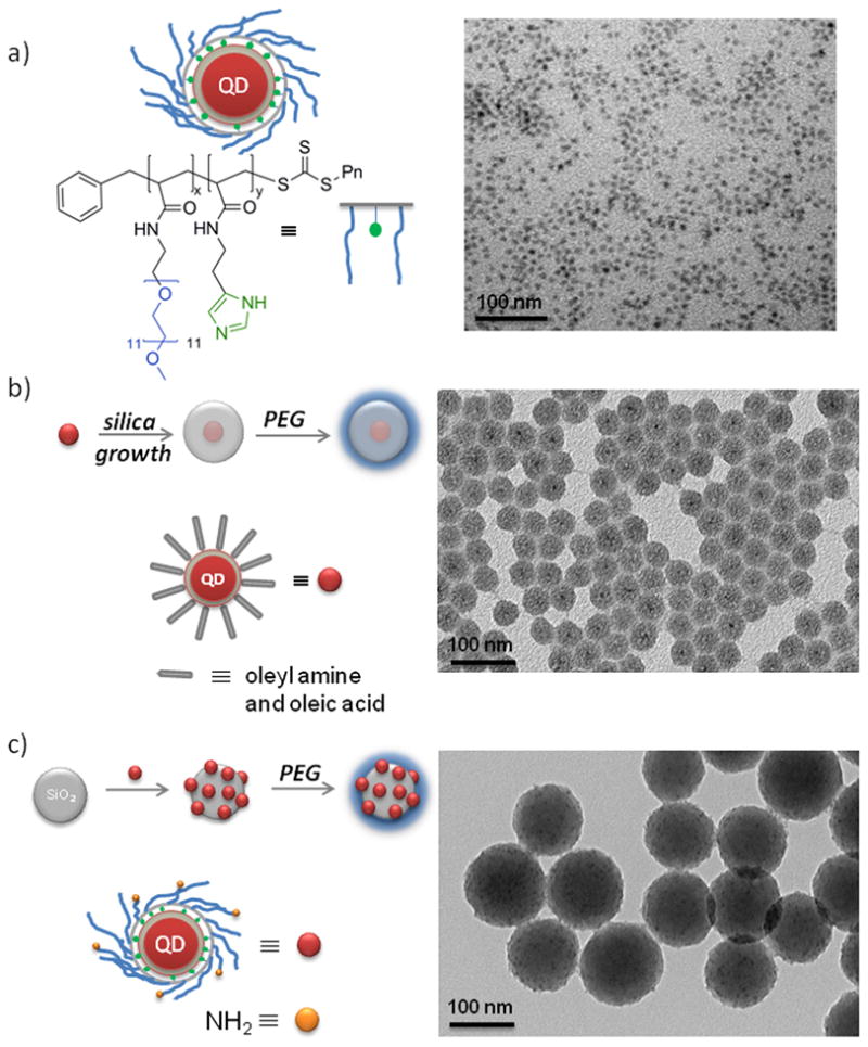
QD-based size series of particles and corresponding TEM images; a) water soluble PIL-coated QDs (10–20 nm), b) single QDs with PEGylated silica shell synthesized via reverse micelles (20–70 nm), and c) silica spheres with electrostatically assembled PIL-coated QDs followed by PEGylation for enhanced stability (100–150 nm). Scale bars are 20nm (a) and 100 nm (b, c) in length.
The thickness of the silica shell was controlled by varying the amount of the silica source. The choice of starting QD structure proved to be crucial for preserving the photoluminescence efficiency of the nanoparticles after the growth of the silica layer. In the case of CdSe/ZnS and CdSe/CdZnS particles, the QD fluorescence was largely quenched after the growth of the silica shell. Conversely, a successful formulation was achieved for CdSe/CdS nanoparticles (4 CdS monolayers, ~95% QY in hexane), which exhibit QY ~40% after silica growth. For particles >100 nm, we used preformed, commercially available silica particles as templates, to which QDs, bearing positive amine groups, were electrostatically assembled (Figure 1c). We found that positively charged QDs rapidly adsorb to negatively charged silica particles when mixed together in water. The optimal loading was determined by adding aliquots of QDs to the silica sphere dispersion and monitoring the size distribution of the silica/QD construct in real time by dynamic light scattering (DLS). Beyond a certain loading, the silica spheres were observed to aggregate in solution. On average each silica sphere was coated with 20–30 QDs. The silica/QD constructs surface were further passivated using siloxane-functionalized methoxy-PEG chains (mPEG) for preventing aggregation and for biocompatibility[17–19] and to satisfy the requirement of a similar surface chemistry across the entire nanoparticle size series.
We found that after the PEGylation step, the QY of QDs assembled onto the preformed silica spheres (>100 nm HD) was ~40% in water. In the case of silica coated QDs (20–70 nm HD), the QY after the PEGylation step was unchanged (~40%) from that before PEGylation. The degree of PEGylation was estimated by thermogravimetric analysis (TGA). For example, it was found that PEG (MW 5000) contributes 2.2% to the PEGylated silica by weight (see Supporting Information). In addition, PEG chain attachment to silica was monitored and verified by ζ-potential measurements of the particles (see Supporting Information). Silica particles that are modified with both QDs and PEG chains have a ζ-potential of −9.0 ± 4.5 mV as a result of the cumulative effect of the addition of PEG and positive QDs. Zeta potentials of PEGylated inversed-micelle QDs and PIL-coated QDs were: −5.9 ± 4.0 mV and 5.1 ± 3.3 mV respectively. Since these zeta potentials are quite small in magnitude, charge should be a negligible factor in their transport behaviour.
The hydrodynamic size of the particles was measured by dynamic light scattering, DLS (Figure 2). All samples were of uniform distribution except for the case of the inverse-micelle QD-silica-PEG5000 (---, Figure 2). In this particular case, the final PEGylation step produced a small amount of broadly distributed aggregates in the 100 nm size range (8.6% by volume). Fluorescence Correlation Spectroscopy (FCS) measurements on this sample shows that only the main fraction around 20 nm is luminescent, indicating that the non-luminescent aggregates likely originate from PEG5000 silane side reactions in the last PEGylation step. Since it is not luminescent, this small aggregate fraction would not interfere with in vivo microscopy measurements.
Figure 2.

Dynamic light scattering (DLS) data for water solutions of PEGylated particles. Peak values from left to right: PIL-coated QDs (–, diameter 10.7 ± 2.4 nm), inverse-micelle QD-silica-PEG5000 (---, diameter 21.6 ± 3.1 nm 91.4% by volume), inverse-micelle QD-silica-PEG5000 (•••••, diameter 56.7 ± 10.1 nm), electrostatically assembled QD-silica-PEG5000 (–•–, diameter 122.4 ± 15.6 nm).
The stability of the final particle constructs was tested by incubating the particles in PBS (4h, 37°C) and measuring particle size with DLS (see Supporting Information). The particles were found to be non-aggregated under these conditions and of the same size as the control particles (4h, RT). We also carried out protein adsorption measurements in order to estimate if the size of the particles would increase in high protein concentration media, thus indicating non-specific binding (see Supporting Information). This experiment is of particular importance because it addresses the question of nanoparticle size behavior under in vivo conditions. After 4h of incubation with Fetal Bovine Serum (FBS) at 37 °C, particles were analyzed by FCS and their size compared to the control particles (incubated in PBS). FCS measurements showed that the size regime of each member of size series was maintained.
To assay the applicability of these nanoparticles as a toolset for probing transport barriers in tumors and assessing drug delivery parameters in vivo, we injected a mixture of these nanoparticles intravenously into a SCID mouse bearing an Mu89 human melanoma xenograft in a dorsal skinfold chamber and carried out intravital multiphoton microscopy on the tumor (Figure 3). To study the effects of size on nanoparticle tumor penetration following extravasation (i.e. distribution of particles from a vessel out into surrounding tissue) in this tumor, we injected a mixture of 12 nm, 60 nm, and 125 nm particles with different emission wavelengths (Figure 3a) and imaged several regions of the tumor over the course of two hours (Figure 3b). Through image analysis consisting of vascular network tracing in 3D and intensity mapping versus distance to the nearest vessel wall,[20] we determined the penetration depth for each nanoparticle (Figure 3c). Figure 3a represents a pseudo color image of the fluorescence over all spectral channels indicating the position of all particles at time 30 min after injection. After an extravasation period of 90 min, the position of particles was determined by recording the fluorescence in defined spectral windows: blue emission for 12 nm particles, red emission for 60 nm particles and green emission for 125 nm particles. Figure 3b shows the resulting fluorescence intensity maps at the 120 min time point after subtracting the corresponding intensity maps at the 30 min time point, thereby showing only the position of those particles that diffused during the 90 min period. If there is no spatial change, the image therefore appears dark. Based on the analysis, the 12 nm nanoparticles extravasate easily, though heterogeneously, and diffuse away from the vessels with minimal hindrance. In contrast, the 60 nm nanoparticles do extravasate but do not leave the immediate perivascular space while the 125 nm particles do not appreciably extravasate. This trend, observed in this particular tumor, is consistent with interstitial transport barriers, such as the extracellular matrix,[21–23] limiting the penetration of nanoparticles of intermediate size while transvascular transport barriers, such as pores in the vessel wall,[4] limiting the extravasation of larger nanoparticles. In order to verify that particle blood clearance is not affecting the extravasation measurements, blood circulation half-lives of size series were estimated (see supporting information for details). We found that 12 nm particles have 24.7 ± 4.0 h circulation half-life while 60 nm and 125 nm particles have 16.6 ± 1.60 and 9.7 ± 0.8 h circulation half-lives, respectively. These circulation times are in the time range of previously reported results[24] and are all significantly longer than extravasation measurements performed in this study (2h).
Figure 3.

Intravital imaging of size-dependent nanoparticle distribution in real time. Intravenous injection into a SCID mouse bearing an Mu89 melanoma in a dorsal skinfold chamber with a mixture of nanoparticles with diameters of 12 nm (476 nm emission), 60 nm (606 nm emission), and 125 nm (540 nm emission). a) Representative multiphoton microscopy image demonstrates the distribution of nanoparticles at 30 min after the injection. b) Multiphoton microscopy images demonstrate distribution of the nanoparitcle in the same resion as (a) at 120 min post-injection (red-yellow hues). The distribution at ~30 min is shown as, dotted white overlay based on 3D vascular tracing. Images are mean intensity projections of 3D volumes; scale bar – 100 μm. c) Penetration depth analysis at 60 min post-injection, with intensity profiles averaged over all 3D vectors normal to the vessels based on 3D vascular tracing. The images and analysis indicate that the 12nm particles effectively extravasate and diffuse away ~100 μm in 60 min, while the 60 nm particles remain within 10 μm of the vessel walls and the 125 nm particles do not appreciably extravasate.
We have developed a size series of luminescent, water soluble particles within the 10–150 nm size range for the purpose of studying the size dependent properties of particle distributions in solid tumors. The size series was designed and constructed to meet each of the multiple criteria required for size dependent in vivo imaging. When simultaneously injected in vivo, the particles show size dependent transport within the same tumors and emerge as a potentially powerful tool for studying biological transport processes. This study demonstrates that QD-based nanoparticles allow direct and simultaneously comparison of different sizes of nanoparticles in a given microenvironment; this technology is promising for use in the quantitative real-time study of transport parameters, the characterization of tissue heterogeneity for drug delivery, the development of in situ tissue microenvironment probes, the measurement of living tissue microrheology, and the screening of tissue modulating therapies for enhancing nanomedicine delivery.
Experimental Section
For a detailed description on synthesis of silica/QD constructs and for measurements of DLS, absolute QY, TGA, ζ-potential, protein adsorption, in vivo imaging and clearance half-lives please see supporting information.
Footnotes
This research was supported by the U.S. National Cancer Institute grants R01-CA126642 (R.K.J, D.F.,M.G.B, and D.G.N), R01-CA085140, R01-CA115767 (R.K.J), P01-CA080124 (R.K.J and D.F), R01-CA096915 (D.F); by the MIT-Harvard NIH Center for Cancer Nanotechnology Excellence (1U54-CA119349) (M.G.B.); by the MIT DCIF (CHE-980806, DBI-9729592); by the ISN (W911NF-07-D-0004) (M.G.B and D.G.N); by the NSF-MRSEC program (DMR-0117795) via the use of its shared user facilities. W.L. was supported by a NSF Graduate Research Fellowship. A.B.G. was a Novartis Fellow of the Life Sciences Research Foundation. We would like to thank S. Geyer for valuable help with quantum yield measurements and to J. Cui for the help with FCS measurements.
Supporting information for this article is available on the WWW under http://www.angewandte.org or from the author.((Please delete if not appropriate))
Contributor Information
Dr. Zoran Popović, Department of Chemistry, Massachusetts Institute of Technology, 77 Massachusetts Ave., Cambridge MA 02139-4307
Dr. Wenhao Liu, Department of Chemistry, Massachusetts Institute of Technology, 77 Massachusetts Ave., Cambridge MA 02139-4307
Vikash P. Chauhan, Edwin L. Steele Laboratory, Department of Radiation Oncology, Massachusetts General Hospital and Harvard Medical School, Boston MA
Jungmin Lee, Department of Chemistry, Massachusetts Institute of Technology, 77 Massachusetts Ave., Cambridge MA 02139-4307.
Cliff Wong, Department of Chemistry, Massachusetts Institute of Technology, 77 Massachusetts Ave., Cambridge MA 02139-4307.
Dr Andrew B. Greytak, Department of Chemistry, Massachusetts Institute of Technology, 77 Massachusetts Ave., Cambridge MA 02139-4307.
Numpon Insin, Department of Chemistry, Massachusetts Institute of Technology, 77 Massachusetts Ave., Cambridge MA 02139-4307.
Prof. Dr. Daniel G. Nocera, Department of Chemistry, Massachusetts Institute of Technology, 77 Massachusetts Ave., Cambridge MA 02139-4307
Prof. Dr. Dai Fukumura, Edwin L. Steele Laboratory, Department of Radiation Oncology, Massachusetts General Hospital and Harvard Medical School, Boston MA
Prof. Dr. Rakesh K. Jain, Edwin L. Steele Laboratory, Department of Radiation Oncology, Massachusetts General Hospital and Harvard Medical School, Boston MA
Prof. Dr. Moungi G. Bawendi, Department of Chemistry, Massachusetts Institute of Technology, 77 Massachusetts Ave., Cambridge MA 02139-4307.
References
- 1.Jain RK. Advanced Drug Delivery Reviews. 2001;46:149. doi: 10.1016/s0169-409x(00)00131-9. [DOI] [PubMed] [Google Scholar]
- 2.Nel AE, Madler L, Velegol D, Xia T, Hoek EM, Somasundaran P, Klaessig F, Castranova V, Thompson M. Nat Mater. 2009;8:543. doi: 10.1038/nmat2442. [DOI] [PubMed] [Google Scholar]
- 3.Perrault SD, Walkey C, Jennings T, Fischer HC, Chan WCW. Nano Letters. 2009;9:1909. doi: 10.1021/nl900031y. [DOI] [PubMed] [Google Scholar]
- 4.Hobbs SK, Monsky WL, Yuan F, Roberts WG, Griffith L, Torchilin VP, Jain RK. Proceedings of the National Academy of Sciences of the United States of America. 1998;95:4607. doi: 10.1073/pnas.95.8.4607. [DOI] [PMC free article] [PubMed] [Google Scholar]
- 5.Yuan F, Dellian M, Fukumura D, Leunig M, Berk DA, Torchilin VP, Jain RK. Cancer Research. 1995;55:3752. [PubMed] [Google Scholar]
- 6.Larsen EKU, et al. ACS Nano. 2009;3:1947. doi: 10.1021/nn900330m. [DOI] [PubMed] [Google Scholar]
- 7.Sarin H, et al. Journal of Translational Medicine. 2008;6:80. doi: 10.1186/1479-5876-6-80. [DOI] [PMC free article] [PubMed] [Google Scholar]
- 8.Farokhzad OC, Langer R. Advanced Drug Delivery Reviews. 2006;58:1456. doi: 10.1016/j.addr.2006.09.011. [DOI] [PubMed] [Google Scholar]
- 9.Bruchez M, Moronne M, Gin P, Weiss S, Alivisatos AP. Science. 1998;281:2013. doi: 10.1126/science.281.5385.2013. [DOI] [PubMed] [Google Scholar]
- 10.Stroh M, Zimmer JP, Duda DG, Levchenko TS, Cohen KS, Brown EB, Scadden DT, Torchilin VP, Bawendi MG, Fukumura D, Jain RK. Nature Medicine. 2005;11:678. doi: 10.1038/nm1247. [DOI] [PMC free article] [PubMed] [Google Scholar]
- 11.Pons T, Uyeda HT, Medintz IL, Mattoussi H. The Journal of Physical Chemistry B. 2006;110:20308. doi: 10.1021/jp065041h. [DOI] [PubMed] [Google Scholar]
- 12.Liu W, Choi HS, Zimmer JP, Tanaka E, Frangioni JV, Bawendi M. Journal of the American Chemical Society. 2007;129:14530. doi: 10.1021/ja073790m. [DOI] [PMC free article] [PubMed] [Google Scholar]
- 13.Zhuang JQ, Wu HM, Yang YA, Cao YC. Journal of the American Chemical Society. 2007;129:14166. doi: 10.1021/ja076494i. [DOI] [PubMed] [Google Scholar]
- 14.Zhuang JQ, Wu HM, Yang YG, Cao YC. Angewandte Chemie-International Edition. 2008;47:2208. doi: 10.1002/anie.200705049. [DOI] [PubMed] [Google Scholar]
- 15.Insin N, Tracy JB, Lee H, Zimmer JP, Westervelt RM, Bawendi MG. ACS Nano. 2008;2:197. doi: 10.1021/nn700344x. [DOI] [PubMed] [Google Scholar]
- 16.Koole R, van Schooneveld MM, Hilhorst J, Donega CD, t Hart DC, van Blaaderen A, Vanmaekelbergh D, Meijerink A. Chemistry of Materials. 2008;20:2503. [Google Scholar]
- 17.Liu W, Greytak AB, Lee J, Wong CR, Park J, Marshal LF, Jiang W, Ting AY, Nocera DG, Fukumura D, Jain RK, Bawendi MG. Journal of American Chemical Society. 2010;132:472. doi: 10.1021/ja908137d. [DOI] [PMC free article] [PubMed] [Google Scholar]
- 18.Meng FH, Engbers GHM, Feijen J. Journal of Biomedical Materials Research Part A. 2004;70A:49. doi: 10.1002/jbm.a.30056. [DOI] [PubMed] [Google Scholar]
- 19.Butterworth MD, Illum L, Davis SS. Colloids and Surfaces a-Physicochemical and Engineering Aspects. 2001;179:93. [Google Scholar]
- 20.Tyrrell JA, di Tomaso E, Fuja D, Tong R, Kozak K, Jain RK, Roysam B. IEEE Trans Med Imaging. 2007;26:223. doi: 10.1109/TMI.2006.889722. [DOI] [PubMed] [Google Scholar]
- 21.Netti PA, Berk DA, Swartz MA, Grodzinsky AJ, Jain RK. Cancer Research. 2000;60:2497. [PubMed] [Google Scholar]
- 22.Chauhan VP, Lanning RM, Diop-Frimpong B, Mok W, Brown EB, Padera TP, Boucher Y, Jain RK. Biophys J. 2009;97:330. doi: 10.1016/j.bpj.2009.03.064. [DOI] [PMC free article] [PubMed] [Google Scholar]
- 23.Magzoub M, Jin S, Verkman AS. FASEBJournal. 2008;22:276. doi: 10.1096/fj.07-9150com. [DOI] [PubMed] [Google Scholar]
- 24.Choi HS, Liu W, Misra P, Tanaka E, Zimmer JP, Ipe BI, Bawendi MG, Frangioni JV. Nature Biotechnology. 2007;25:1165. doi: 10.1038/nbt1340. [DOI] [PMC free article] [PubMed] [Google Scholar]