

Abstract
We present the first electrochemical actuator with Parylene bellows for large-deflection operation. The bellows diaphragm was fabricated using a polyethylene-glycol-based sacrificial molding technique followed by coating in Parylene C. Bellows were mechanically characterized and integrated with a pair of interdigitated electrodes to form an electrochemical actuator that is suitable for low-power pumping of fluids. Pump performance (gas generation rate and pump efficiency) was optimized through a careful examination of geometrical factors. Overall, a maximum pump efficiency of 90% was achieved in the case of electroplated electrodes, and a deflection of over 1.5 mm was demonstrated. Real-time wireless operation was achieved. The complete fabrication process and the materials used in this actuator are bio-compatible, which makes it suitable for biological and medical applications.
Keywords: Bellows, drug delivery device, electrolysis pump, intraocular implant
I. Introduction
AFTER SEVERAL decades of development, many micropumps, including mechanical and nonmechanical, have been demonstrated [1]. Mechanical micropumps may incorporate check valve [2] or valveless [3] approaches to regulate flow direction and include a compliant element for pumping. Typically, large flow rates can be realized (> 10 μL/min). Nonmechanical pumps are driven by electrohydrodynamic [4], electrowetting [5], magnetohydrodynamic [6], phase transformation [7], or electrochemical [8] principles but usually suffer from low achievable flow rates (< 10 μL/min). Among them, electrochemically driven mechanical pumps feature low power consumption, low heat generation, accurate flow control, and large driving force [9], [10]. These factors, combined with the potential for biocompatible construction, afford many interesting biological and medical applications.
Implantable microelectromechanical systems (MEMS) pumps are still an active area of research; specifically, achieving integration of the entire pumping systems remains difficult. Although many nonmechanical pumps cite the possibility of use in drug delivery applications, clinical or in vivo experimental data are rarely seen. Most implantable pumps in literature are still mechanical [11]. The major design concerns for an implantable drug delivery system are as follows: applied voltage, power consumption, dosing accuracy, concentration, frequency, duration, toxicity, drug interaction, and allergies.
Previously, we reported a drug delivery system integrated with an electrochemical micropump for the treatment of intraocular diseases [12]. This pump was integrated with an interdigitated electrode to induce electrochemical phase change of liquid water into hydrogen and oxygen gas for drug delivery. However, oxidation of the drug was observed due to the direct electrolysis of the drug during pumping. Therefore, a separate pumping chamber is required to prevent drug degradation and unwanted pH changes. A simple solution is to mechanically couple the pumping chamber to the drug through a flexible diaphragm.
Parylene diaphragms are widely used in micropumps because of their advantageous properties compared to other thin film materials [13], [14]. First, it is a United States Pharmacopeia class VI polymer and highly inert. It is also compatible with MEMS microfabrication. In addition, Parylene has low Young's modulus which grants large displacement in fabricated diaphragms with low applied pressure. Several Parylene diaphragm geometries have been investigated: flat [15]–[17], dome [18], corrugated [13], [15], [19], [20], and bellows [21], [22]. Among them, corrugated diaphragms and bellows provide the largest deflections (> 1 mm), possess low intrinsic stress, and thus are less likely to undergo plastic deformation compared to flat and dome diaphragms. Corrugated diaphragm fabrication, however, is complex due to the requirement of deep corrugation trenches for large-deflection membrane. Current etching technologies such as wet chemical etching and dry plasma etching are both limited to the substrate thickness (~500 μm for 3–4-in Si wafers). Therefore, the practically achievable corrugation depth is less than 500 μm and places a limit on deflection. Meanwhile, wet-etched corrugations may be associated with residual stress which may result in deformation during the substrate release step.
Microbellows are also difficult to fabricate due to the horizontal convolutions comprising the bellows structure. A common process to produce each bellows convolution involves the deposition and patterning of the sacrificial layer followed by the diaphragm material. By repeating these steps, silicon nitride microbellows were fabricated [23]. An alternative process resulted in Parylene bellows by using a wax mold as a sacrificial material [21], [22]. Other technologies involved in microbellows fabrication are microstereolithography [24] and focused-ion-beam chemical vapor deposition [25]. For micromachining and wax molding, acid or solvent is required for removal of the sacrificial materials. Elevated temperatures encountered during sacrificial release may also induce residual stress in the bellows.
Polyethylene glycol (PEG), a biocompatible and water-soluble polymer [26], is a widely used biomedical material. It is patternable by conventional photolithography [27] and soft lithography [28]. Casting of PEG structures for corrugated Parylene diaphragm was reported [29]. A maximum deflection of 0.9 mm was demonstrated for a 2.6-mm-diameter corrugated diaphragm. Microbellows, however, have not yet been realized by coating over sacrificial PEG casts.
Here, we present a novel Parylene bellows electrochemical actuator. The Parylene bellows is fabricated using a sacrificial PEG molding technique followed by Parylene coating. Only biocompatible materials and solutions are used to produce the Parylene bellows. The large convolutions offer large deflection under a low actuation pressure. By combining the bellows with a pair of interdigitated electrodes, a complete actuator system was assembled. In the literature, characterization of ohmic loss [30] of, electrosynthesis [31] with, and electrochemical sensing [32] using interdigitated microelectrodes were investigated. However, the relationship between interdigitated electrode geometry (specifically electrode element width and spacing) and pump efficiency is not fully characterized. Therefore, an experimental method to evaluate the pump performance based on efficiency was pursued. Actuator performance was characterized, including flow rate, efficiency, real-time pressure generation, and wireless operation.
II. Design
Key actuator features include the following: 1) separation of the electrochemical reaction from the pumped solution by a robust high-deflection Parylene bellows; 2) an efficiency-optimized electrolysis electrode design to minimize power consumption for long-term wireless operation; and 3) construction from biocompatible materials.
The pump actuator consists of interdigitated platinum electrodes and Parylene bellows that are fabricated separately. Assembly involves first filling the bellows with deionized (DI) water and then joining it to the electrode base to seal the electrochemical chamber [Fig. 1(a)]. The interdigitated electrode geometry minimizes the resistive path through the solution to improve pumping efficiency and reduce heat generation [30]. Electrolysis pumping is selected over other actuation methods for its low power consumption (from approximately microwatts to milliwatts) which is achieved without compromising deflection and force (Fig. 2).
Fig. 1.

Parylene bellows electrochemical actuator for ocular drug delivery: (a) Exploded view of the actuator showing the major components, (b) example of the actuator assembled into a drug delivery system, and (c) conceptual depiction of the implanted intraocular drug delivery device. The device is implanted under the conjunctiva (within the eyewall) with the cannula directed through an incision into the anterior segment of eye.
Fig. 2.
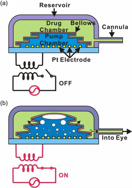
Illustration of wireless operation of the intraocular drug delivery system: (a) power off and (b) power on.
Bellows provide large displacement while requiring minimal driving force compared to other commonly used diaphragm geometries. For example, a flat membrane has very limited deflection and thus is only suitable for low-flow applications [23]. Large deflections are possible but at the cost of large membrane size. Corrugated membranes achieve larger deflection without significant increase in size. However, deep corrugations (> 1 mm) are difficult to fabricate, and only a limited number or corrugations fit within a given diaphragm area. These factors impose a practical limit to deflection achievable with corrugated diaphragms. Bellows grant the largest displacement of these three options (flat, corrugated, and bellows diaphragms) with a minimal increase in overall thickness. Fabrication of bellows by standard lithographic processes is repetitive and time consuming [23]. A simple lithography-less approach to bellows fabrication was devised here to produce flexible Parylene bellows.
Our specific application of interest is a micropump for ocular drug delivery [Fig. 1(b) and (c)]; the envisioned system consists of a reservoir containing the actuator and a cannula through which drug is dosed. The reservoir body is implanted within the eye wall, while the cannula is inserted through an incision and directed to the site of therapy in the intraocular space. Wirelessly-transferred power is applied to the interdigitated electrodes to induce electrolysis (phase change of water into hydrogen and oxygen gas), which results in an internal pressure increase within the actuator and inflates the bellows [Fig. 2(b)]. The inflated bellows drives the drug through the cannula into the eye, while the gases remain trapped inside the pump chamber, preventing undesirable contact with the drug. Control of drug delivery can be achieved by adding a dual-regulating check valve connected to the end of the cannula to prevent both backflow of the drug into the device and accidental delivery resulting from transient pressure fluctuations (e.g., as a result of flying or sneezing) [33].
III. Theory and Modeling
A. Electrolysis Actuation Using Microelectrodes
Electrolysis of water was selected as the actuation mechanism for low power consumption, high pump efficiency, simple structure, and ability to generate large displacements [9], [34].
1) Actuation Force
The electrochemical reactions involved in the electrolysis of water are
| (1) |
At room temperature, a volume expansion from liquid water to gas phase hydrogen and oxygen on the order of a thousand times is achieved. This large volume change provides an excellent mechanical power source, and it proceeds even in a pressurized environment [35].
2) Pump Efficiency
The efficiency (η) associated with the electrolysis reaction is calculated from
| (2) |
where Vexperimental is the total volume of the generated hydrogen and oxygen gases and Vtheoretical is the theoretical volume of the generated gas bubbles [10]. Vexperimental is determined experimentally, and Vtheoretical is calculated from
| (3) |
where qtheoretical is the theoretical gas generation rate (in cubic meters per second), t is the duration (in seconds) over which the current is applied, i is the current (in amperes), F is Faraday's constant (96.49 × 10⁻³ C/mol), and Vm is the molar gas volume at 25 °C and atmospheric pressure (24.7 × 10⁻³ m3/mol).
3) Power Consumption
In addition to high actuation force, the actuator should minimize both power consumption and heat generation. The voltage requirement for electrolytic water decomposition can be calculated from the Nernst equation
| (4) |
Here, E is the electromotive force, F is the Faraday constant, ΔG0 is the Gibbs free energy under standard conditions, R is the gas constant, T is the temperature, pH2 and pO2 are the partial pressures of the gases, and a is activity. Under standard conditions (25 °C and 1 atm), the minimum voltage required for electrolysis is ideally 1.23 V [36]. In practice, the applied voltage U required to initiate electrolytic water decomposition is larger than the theoretical minimum and is expressed as
| (5) |
where εa and εc are the overpotentials of the anode and cathode, respectively, and IR is the ohmic drop due to the electrolyte. Ohmic loss is largely dependent on the distance between the electrodes and may result in higher power consumption and unwanted heat generation, particularly when pure water is used as the electrolyte. This ohmic drop can be reduced by shortening the current path through the electrolyte, using an electrolyte with greater ionic concentration, or by increasing the surface area of the electrode [30].
B. Mechanical Modeling of Parylene Diaphragms
We evaluated the mechanical performance for the two diaphragm geometries considered for our actuator: corrugated membranes and bellows. Both are capable of large deflection under low internal loadings compared to flat membranes [15], [23]. Mechanical modeling aided final selection of the bellows geometry. Finite-element models (FEMs) were developed. In addition, a theoretical linear bellows approximation was also evaluated.
1) FEM Modeling
Nonlinear static simulation of the corrugated membrane and bellows was performed using FEM (Nonlinear StaticV2007 SP4 Solver, COSMOSWorks 2007, SolidWorks Co., Concord, MA) (Fig. 3). Quarter models were used due to geometric symmetry. The diaphragm dimensions, mechanical properties of the materials, and applied loads used in this FEM study are listed in Table I. A corrugation depth of 200 μm was selected based on practical trench depths by deep reactive-ion etching of silicon.
Fig. 3.
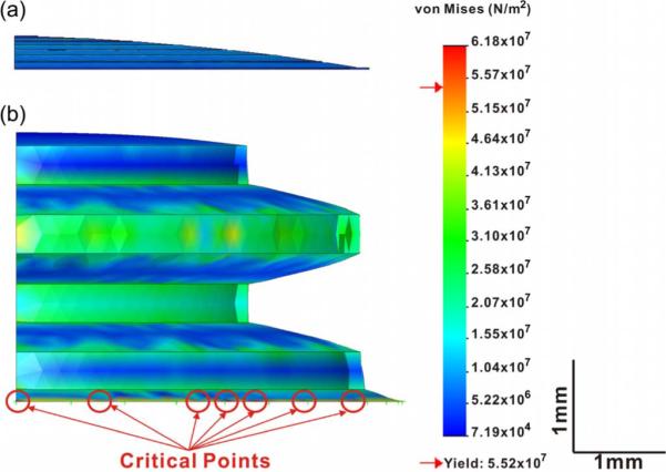
Finite-element analysis using COSMOSWorks showing stress distribution for (a) Parylene corrugated membrane and (b) bellows. Critical stress sites are also indicated in the graph.
TABLE I.
Material Properties, Parameters, and Diaphragm Dimensions Used in Finite-Element Modeling
| Properties, Parameters, or Dimensions | Values |
|---|---|
| Density of Parylene (kg·m−3) | 1289 |
| Young's Modulus of Parylene (GN·m−2) | 2.76 |
| Tensile Strength of Parylene (MN·m−2) | 68.9 |
| Yield Strength of Parylene (MN·m−2) | 55.2 |
| Poisson's Ratio of Parylene | 0.40 |
| Applied Pressure (kN·m−2) | 3.44 |
|
| |
| 1. Dimensions of Corrugated Diaphragm | |
|
| |
| Thickness of Parylene Membrane (μm) | 10.0 |
| Diameter of Diaphragm (mm) | 9.0 |
| Depth of Corrugations (μm) | 200 |
| Number of Corrugations | 4 |
| Maximum Deflection (mm) | 0.8 |
|
| |
| 2. Dimensions of Bellows Diaphragm | |
|
| |
| Thickness of Parylene Membrane (μm) | 10.0 |
| Inner Diameter of Bellows | 6.0 |
| Outer Diameter of Bellows | 9.0 |
| Number of Bellows Convolutions | 1.5 |
| Maximum Deflection (mm) | 1.5 |
2) Linear Bellows Approximation
The linear bellows approximation [37] is
| (6) |
where δ is the bellows deflection, n is the number of convolutions, ν is Poisson's ratio, a is the inner radius of the bellows, b is the outer radius of the bellows, P is the uniform applied pressure, E is Young's modulus of Parylene, and h is the wall thickness of the Parylene bellows. This equation assumes that operation in the elastic range, the thickness of the bellows diaphragm is uniform, and no buckling of bellows occurs [38]. Later, deflections obtained with this equation were compared with FEM simulation and experimental results.
IV. Fabrication
A. Pump Electrodes
Interdigitated electrodes were fabricated on glass substrates by a liftoff process (Fig. 4). A dual-layer photoresist process was used to create an undercut sidewall profile to facilitate metal liftoff. First, AZ1518 photoresist (AZ Electronic Materials, Branchburg, NJ) was spun at 4000 r/min followed by global exposure. Then, AZ4400 photoresist (AZ Electronic Materials, Branchburg, NJ) was applied at 4000 r/min and patterned [Fig. 5(a)]. Following a short descum in oxygen plasma, a Ti/Pt film (300 Å/2000 Å) was e-beam evaporated [Fig. 5(b)]. The pump electrodes were defined by liftoff [Fig. 5(c)].
Fig. 4.

Photographs of interdigitated Pt/Ti electrode layout for electrochemical actuator showing (a) fixed-width variable spacing electrodes, (b) variable width and spacing electrodes, and (c) close-up of (b). The electrode element spacing and width are also defined in (c).
Fig. 5.
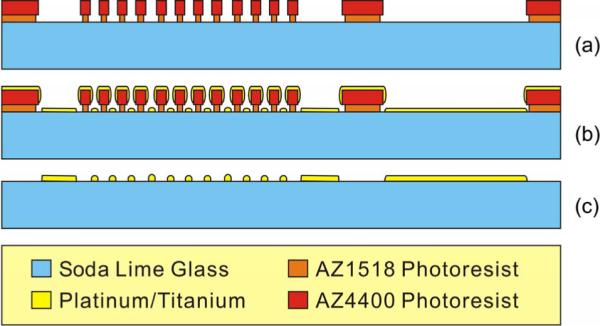
Fabrication process flow for the pump interdigitated electrode: (a) Liftoff lithography, (b) Ti and Pt e-beam evaporation, and (c) Pt liftoff.
B. Molded Parylene Bellows
The bellows fabrication process, dissolvable PEG mold, and fabricated bellows are shown in Fig. 6. First, a pressure-sensitive adhesive film (1.5 cm × 1.5 cm, Scotch Magic Tape 810, 3M, St Paul, MN) was affixed to a glass slide, and a 6-mm-diameter piece was removed from the center [Fig. 6(a)]. This film facilitated the mold release process. Four 400-μm-thick silicone sheets (2 cm × 2 cm, Sylgard 184, Dow Corning, Midland, MI) were obtained (10 : 1 base-to-curing agent ratio) by spin coating (500 r/min) on a Parylene C (Special Coating Systems, Inc., Indianapolis, IN) coated soda lime wafer. The casted film was degassed and cured in vacuum at 65 °C for 1 h (V0914 vacuum oven, Lindberg/Blue, Asheville, NC). Holes were punched into each sheet; two hole sizes were used [diameters of 6 mm (internal) and 9 mm (external)]. Each sheet produced half of one convolution, and these sheets were manually aligned and stacked on the taped slide such that hole sizes alternated to produce the master mold [Fig. 6(a)]. Bubbles trapped between silicone sheets were eliminated by evacuation, and the mold was reinforced around the periphery with an additional layer of silicone (65 °C for 1 h) prior to PEG molding [Fig. 6(b)]. Then, molten PEG (85 °C) (14 000 MW, Sigma-Aldrich, St. Louis, MO) was poured into the silicone mold and degassed [Fig. 6(c)]. After cooling, the silicone was released, and the casted PEG was coated with 10 μm of Parylene C [Fig. 6(d)]. The bellows was released from the glass slide by lifting the adhesive film, and the sacrificial PEG was removed in heated DI water (85 °C for 2 h) [Fig. 6(e)]. Finally, the Parylene bellows was separated from the adhesive film [Fig. 6(f)].
Fig. 6.

Bellows molding process. (a)–(f) Fabrication steps for the bellows. (g) Photographs of the PEG mold. (h) Parylene bellows. The inset in (h) shows a close-up of the top bellows convolution.
C. Actuator Assembly
The assembly process of the electrochemical actuator is shown in Fig. 7. The bellows half of the actuator was first filled with DI water, degassed in a vacuum oven (V0914 vacuum oven, Lindberg/Blue, Asheville, NC), and attached to the pump base using a laser cut (Mini/Helix 8000, Epilog, Golden, CO) double-sided pressure-sensitive adhesive film (Tape 415, 3M, St. Paul, MN) [Fig. 7(a)]. A metal ring (~50 g) was applied on the bonding region for 24 h as a uniform load to enable a maximum bonding strength between the bellows and the glass substrate. The maximum tensile bonding strength of the tape is around 70–200 psi (0.48–1.38 MPa) which is far greater than the maximum bellows internal pressure of 0.5 psi (data shown in later section) generated by the electrolysis gases. In addition, epoxy (5 Minute Epoxy System, ITW Performance Polymers, Riviera Beach, FL) was applied at the bonded edge to reinforce the seal and prevent the leakage of the pump fluid into the drug chamber during operation [Fig. 7(b)].
Fig. 7.

Parylene electrochemical bellows actuator. (a) Schematic diagram of the two-part assembly. (b) Image of assembled actuator.
D. Electroplated Electrodes
Electrodes with higher surface roughness were produced by electroplating on e-beam deposited Pt. The electrodes were connected to a potentiostat in a three-electrode cell configuration with an Ag/AgCl reference electrode. The electroplating solution consisting of (NH4)2PtCl6 was held at a near neutral pH of ~7.8 [39]. Potentiostatic deposition (−0.5 V for 15 min) was performed, and then, the devices were flushed with DI water and blown dry with filtered N2.
V. Experimental Methods
Bellows were evaluated in load–deflection experiments and then compared to results from the linear bellows approximation and FEM. To decrease the power consumption of the pump for wireless operation, pump efficiency was optimized through an investigation of electrolysis electrode geometry. Assembled actuators combining both electrodes and bellows were examined in a continuous delivery mode under a constant applied current. Internal pressure generated over time was measured, and wireless operation was performed.
A. Mechanical Characterization of the Bellows
A 10-μm-thick Parylene bellows diaphragm was clamped into a laser-machined acrylic test fixture. The fixture input was connected to a regulated pressure source that supplied a uniform load [0.25–0.5 psi (1.72–3.44 kPa) with pressure increments of 0.05 psi (0.344 kPa)]. The deflections of the bellows under applied pressures were measured using a compound microscope (PSM-1000, Motic China Group Co., Xiamen, China) with a vertical focus resolution of 1 μm [Fig. 8(a)].
Fig. 8.

Schematic diagrams of the experimental apparatus for (a) Parylene bellows load–deflection testing, (b) flow rate testing for the (top inset) electrodes and (bottom inset) assembled bellows actuator, (c) real-time pressure monitoring, and (d) wireless operation.
B. Pump Efficiency
To determine the impact of interdigitated electrode geometry on pumping efficiency, two sets of experiments were performed with differing electrode designs. The first design was based on a rectangular layout and maintained constant electrode area and fixed element width but varied element spacing. In the second experimental set, both element width and spacing were varied for a circular electrode layout. Flow rates were measured, and the corresponding pump efficiency was calculated for each electrode design.
1) Fixed-Width Variable Spacing Electrodes
Five interdigitated electrode designs with fixed element width and variable element spacing for a rectangular pumping area were investigated (Table II). The number of elements remained constant in all designs. Previously, Belmont demonstrated that the resistance between the cathode and anode decreased as element spacing decreased [30]. However, the relation between pump efficiency and electrode geometry was not determined. Electrodes were mounted in a custom laser-machined (Mini/Helix 8000, Epilog, Golden, CO) acrylic test fixture. A computer-controlled charge-coupled device camera (PL-A662, PixeLINK, Ottawa, ON, Canada) collected flow data from a calibrated micropipette (Accu-Fill 90, Becton, Dickinson and Company, Franklin Lakes, NJ) connected to the output of the test fixture [Fig. 8(b)]. DI water served as the electrolyte. Electrolysis was sustained under constant current conditions (1.0 mA) (2400 Sourcemeter, Keithley, Instruments Inc., Cleveland, OH) for continuous delivery operation. The pump efficiency was calculated using (2).
TABLE II.
Electrode Parameters for Fixed-Width Variable Spacing Electrodes
| Element Width (μm) | Element Spacing (μm) |
|---|---|
| 150 | 25 |
| 150 | 50 |
| 150 | 100 |
| 150 | 150 |
2) Variable Width and Spacing Electrodes
The 12 electrode designs examined are shown in Table III. The electrodes were laid out in a circular area to match the bellows geometry (9 mm in diameter). Here, the number of elements varied in each design. The same experimental setup and methods for evaluated fixed-width electrodes were used here. Although the overall electrode area varied, the same test fixture was used, and thus, the pumping chamber volume was held constant.
TABLE III.
Electrode Parameters for Variable Width and Spacing Electrodes
| Element Width (μm) | Element Spacing (μm) | Electrode Area (mm2) |
|---|---|---|
| 20 | 20 | 20.0 |
| 20 | 50 | 11.2 |
| 20 | 100 | 7.0 |
| 50 | 20 | 29.8 |
| 50 | 50 | 20.2 |
| 50 | 100 | 14.2 |
| 100 | 20 | 34.6 |
| 100 | 50 | 27.4 |
| 100 | 100 | 21.4 |
3) Electroplated Interdigitated Electrodes
One device (circular interdigitated electrodes with an element width of 100 μm and element spacing of 20 μm) was electroplated to increase the electrode surface roughness to determine its impact on pump efficiency. The gas generation rate before electroplating was first measured. Cyclic voltammetry (CV) and electrochemical impedance spectroscopy were used to characterize the surface roughness of the electrodes before and after electroplating (Potentiostat 273A, Princeton Applied Research, Oak Ridge, TN). H2SO4 (0.5 M) was used as the electrolyte in both cases. Finally, the gas generation rate of the electroplated device was measured (applied current of 0.2–0.8 mA) to obtain a before–after comparison.
C. Flow Rate
Assembled bellows actuators were evaluated using the same test fixture and mounted as shown in Fig. 8(b). Fluid was pumped under a constant current (0.2–1.0 mA), and the associated pump efficiency was calculated from (2).
D. Real-Time Pressure Measurement
Real-time measurements of electrolysis chamber pressure were collected at different currents to characterize actuator performance. Pressure was also tracked for on–off operation of the pump. A pressure sensor (ASDX015D44R, Honeywell International Inc., Morristown, NJ) with a response time of 8 ms was connected to the outlet of the test fixture, and its output signal was fed into a data acquisition unit (LabVIEW 7.1 with 2700 DAQ, Keithley Instruments Inc., Cleveland, OH) [Fig. 8(c)].
E. Wireless Operation
A wireless inductive power transfer system specifically developed for biomedical implants was adapted for use with our actuator (2 MHz) [Fig. 8(d)] [40]. RF power was transferred between a primary and a secondary coil; only interdigitated electrodes were attached to the secondary coil through a four-diode ac/dc rectifying circuit. Operation with two types of coils was performed: 1) a hand-wound Litz wire coil and 2) a coil patterned on a printed circuit board (PCB). Rectangular interdigitated electrodes with an element width of 150 μm and spacing of 100 μm were used.
VI. Results and Discussion
A. Mechanical Characterization of the Bellows
Bellows were selected as the actuator diaphragm for its superior deflection with lower material stress based on nonlinear FEM results. Critical stress points were identified at the bottom edge of the bellows [Fig. 3(b)]. Bellows achieved greater deflection compared to corrugated membranes (1.5 mm versus 0.8 mm for 10-μm-thick membranes) under a 0.5-psi (3.44-kPa) applied pressure. The maximum stress imposed on the bellows under the 0.5-psi (3.44-kPa) applied pressure was 61.8 MPa which is less than the tensile strength (68.9 MPa) but higher than the yield strength (55.2 MPa) of Parylene. However, these critical stress sites are limited to small regions, and the bellows is expected to survive pressurized conditions that arise during electrolysis loading.
The load–deflection experiments agreed with the FEM results but not with the linear bellows approximation (Fig. 9). The large mismatch in the latter is likely due to the nonlinear nature of Parylene (a typical inelastic material with plastic nonlinear response), scaling effects, and the low number of bellows convolutions (n = 1.5). Although the linear approximation is widely used to characterize macroscale bellows with a large number of convolutions, it does not offer practical insights on the mechanical performance of our microbellows. Experimentally, an average maximum deflection of 1.78 mm was obtained compared to 1.5 mm for the nonlinear FEM under a 3.44-kPa (0.5-psi) applied pressure. This relatively large deformation under low-pressure loading compared to the starting height of the bellows (1.6 mm) suggests the low pumping resistance of the Parylene bellows which is desirable for lower power consumption.
Fig. 9.
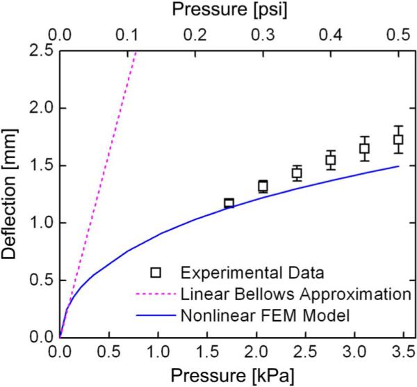
Comparison of load-deflection experimental data with linear approximation and nonlinear FEM model for the Parylene bellows diaphragm (mean ± SE, n = 4).
B. Pump Efficiency
1) Fixed-Width Variable Spacing Electrodes
The gas generation rate and pumping efficiency were measured and calculated, respectively (Fig. 10). Gas generation and, thus, pumping efficiency improved with decreasing element spacing. For smaller element spacings, efficiency remained constant and did not improve further. From (5), the overpotential components (εa and εc) and the electromotive force (E = 1.23 V [36]) are the same or constant for all the five devices tested here. Therefore, the ohmic drop term IR is the only variable in this experiment. Given that the applied current is held at 1 mA and the electrode surface area is constant, current density is also constant. Therefore, the results indicate that decreasing element spacing reduces resistance and improves pumping efficiency.
Fig. 10.
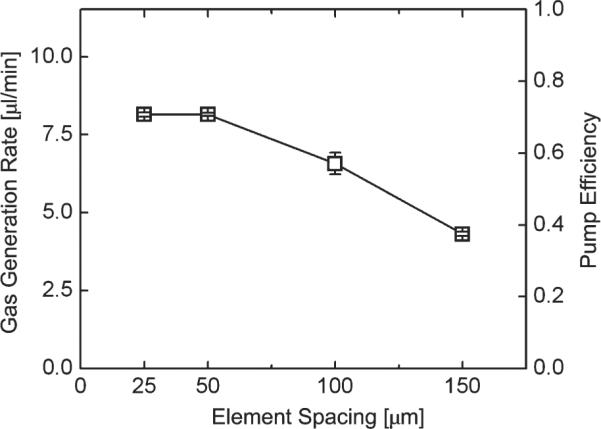
Pump efficiency optimization based on current-controlled gas generation for fixed-width variable spacing electrodes. Pump efficiency increases with decreasing element spacing (mean ± SE, n = 4).
2) Variable Width and Spacing Electrodes
Gas generation and pump efficiency were measured and calculated, respectively [Fig. 11(a) and (b)]. Unlike the constant area electrodes, gas generation and pumping efficiency increased with element spacing. A peak efficiency was identified corresponding to the electrode with elements measuring 50 μm wide and having a 100 μm spacing. No obvious trends can be extracted from these experimental results. From (5), unlike the previous case, the overpotential components (εa and εc) are not constant due to the variation of electrode width (or electrode area) and number of elements. This variable electrode area also influences the ohmic loss IR. However, the dependence of each of these factors (εa, εc, I, and R) in (5) on electrode area and element number is complex. Further investigation with systematic optimization methods is required.
Fig. 11.

Pump efficiency optimization based on current-controlled flow delivery for the constant pump area interdigitated electrodes. (a) Pump efficiency versus current density (mean ± SE, n = 4) and (b) pump efficiency versus element spacing and width results were obtained from electrodes fabricated using the optimized process. (c) Pump efficiency versus current density (mean ± SE, n = 4) and (d) pump efficiency versus element spacing and width results were obtained from electrodes fabricated using the unoptimized process.
In the first batch of electrodes, delamination of the Ti/Pt layer was observed for elevated currents (> 1.0 mA). The premature electrode failure was attributed to poor adhesion between the Ti/Pt and glass substrate. A second batch of electrodes was fabricated using a modified descum process and e-beam deposition vacuum pressure (Table IV). Both sets of electrodes were flow tested under a 1 mA applied current for 10 min [Fig. 11(a)–(d)]. The data confirmed that improved adhesion by the process modification resulted in robust electrodes that did not delaminate even under application of higher currents (up to 10 mA).
TABLE IV.
Fabrication Parameters Used in Electrode Patterning Process
| Liftoff Process Parameters | Unoptimized | Optimized |
|---|---|---|
| Reactive Ion Etching Descum | ||
|
| ||
| Power (W) | 60 | 100 |
| Pressure (mTorr) | 100 | 100 |
| Time (sec) | 30 | 60 |
|
| ||
| E-Beam Metal Evaporation | ||
|
| ||
| Initial Vacuum Pressure (mTorr) | ~10−7 | ~10−8 |
Interestingly, although electrode delamination was observed in the first batch of electrodes, a greater pump efficiency was also obtained (~80% compared to 49%). This efficiency increase is likely attributed to the surface area increase following delamination. Element electrodes of 20 μm wide peeled off after 10 min of 1 mA applied current, while thicker elements (100 μm wide) experienced modest delamination mostly confined to feature edges. Thus, thinner elements with less contact area are at higher risk for delamination. Although this phenomenon increases pumping efficiency, the delicate electrodes may break off and result in undesirable short circuits.
Constant current (1–5 mA for 10 min each) was applied to the new electrodes (both types) with improved adhesion to induce flow, and the corresponding pump efficiency was calculated as shown in Fig. 12. In Fig. 12(a) and (b), efficiency remained constant over the range of applied currents. However, in Fig. 12(c) and (d), a significant increase in efficiency was observed over the current range tested, and efficiency even exceeded 90% at 4 and 5 mA [Fig. 12(c) and (d)]. The increase in efficiency is likely due to slight delamination of the narrow electrode element resulting in an increase in surface area; however, evidence of this modest delamination was difficult to capture under optical microscopy. Higher applied currents of 10 and 50 mA were also examined (data not shown). Electrodes survived 10 mA for 10 min but failed immediately at 50 mA. For normal ocular drug delivery [12], a flow rate of < 2 μL/min is acceptable. The corresponding driving current is usually less than 0.5 mA. However, other drug delivery applications may require higher flow rates and thus higher currents; this is now possible with the improved electrodes.
Fig. 12.

High applied current experiments. [(a) and (b)] Gas generation rate and calculated pump efficiency results for fixed-width variable spacing electrodes. [(c) and (d)] Gas generation rate and calculated pump efficiency results for variable width and spacing electrodes.
3) Electroplated Interdigitated Electrodes
SEM images [Fig. 13(a) and (b)] confirm the surface roughness increase following electroplating. Pumping performances before and after electroplating were compared [Fig. 13(c)–(f)]. Analysis of the CV plot [Fig. 13(c)] suggests ~9.6 × electrode surface area increase. The impedance also decreased by three orders of magnitude at 0.1 Hz as shown in Fig. 13(d). The measured gas generation rate and the corresponding pump efficiency calculated demonstrate a remarkable improvement in pump performance simply by increasing the electrode surface area through plating [Fig. 13(e) and (f)]. Electroplated platinum electrodes are commonly used in neural stimulation [41] and exhibit good corrosion resistance [42]. However, delamination of electroplated Pt was observed and must be further investigated to obtain robust films that are necessary for long-term operation.
Fig. 13.

Electroplated electrode experimental results. SEM images of the e-beam evaporated electrode surface (a) before electroplating and (b) after electroplating. Electrode electrochemical characterization before and after electroplating: (c) CV and (d) electrochemical impedance plots. Electrolysis pumping performance before and after electroplating: (e) pump flow rate and (f) pump efficiency.
C. Flow Rate
In assembled bellows actuators, flow rates up to 6.5 μL/min (1 mA) were obtained (Fig. 14). At applied currents below 0.2 mA, no flow was observed due to the competitive recombination of hydrogen and oxygen into water catalyzed by Pt. An efficiency of ~50% was achieved. Flow data are in close agreement with those of preassembled devices. The seal between the bellows and pump base in the actuator assembly withstood repeated operation of the bellows actuator. No leakage was observed.
Fig. 14.

Flow rate testing for Parylene bellows actuator: (a) Current-controlled delivery collected from 20-μm-width and 100-μm-gap device (mean ± SE, n = 4) and (b) calculated pump efficiency.
D. Real-Time Pressure Measurement
Electrolysis chamber pressure under continuous and on-off operation was measured (Fig. 15(a) and (b), respectively). First, the former increases in a predicable linear manner for constant applied current [Fig. 15(a)]. This demonstrates that continuous constant flow rate pumping is possible given an adequate fluid reservoir volume. The highlighted region corresponds to the normal intraocular pressure (IOP) range [5–22 mmHg or 15.5 ± 2.6 mmHg (mean ± SD)] [43]. Elevated IOP levels (> 22 mmHg) are a characteristic of glaucoma which is a common chronic ocular disease. Regardless of the backpressure contributed by IOP, the electrolysis pump is easily able to overcome the pressure head and pump fluids into the eye. In addition, demonstration of on-off mode operation indicates that pulsatile or bolus delivery is possible [Fig. 15(b)]. Notably, the pressure decrease is correlated closely with the recombination of hydrogen and oxygen that occurs in the presence of Pt which serves as a catalyst. Gas recombination was also reported in similar electrolysis pumps [10], [12]. In our previous study [12], a typical recombination rate of 62 nL/min was measured. Recombination of gases reduces both pressure and gas volume, which restores the bellows to its original resting position.
Fig. 15.

Real-time pressure measurement of Parylene bellows actuator: (a) In actuator chamber and (b) during on (2-min) and off (3-min) operations.
Since both drug and pump chambers are filled with liquids, diffusion of the gas through the Parylene bellows is expected to be minimal. However, a composite bellows (Parylene/metal/Parylene) can be used in place of the Parylene bellows to minimize gas diffusion. Even if gas escape is present, it will not adversely affect the eye since air bubble introduction is routine during eye surgery. Furthermore, gas escape is not expected to significantly impact electrolysis actuation. The volume expansion from liquid phase water to gas phase oxygen and hydrogen is greater than a thousandfold. Thus, for a 100-μL-volume drug reservoir, the minimum volume of the actuator chamber (the volume enclosed by the bellows) is only 0.1 μL. Therefore, the current actuator chamber of 46 μL (≫ 0.1 μL) is more than sufficient for electrolysis pumping. In our previous work [12], we also demonstrated electrolysis actuation against backpressure. The values of these backpressures were based on physiological and abnormal IOP values (0, 20, and 70 mmHg). No obvious difference in the flow rate between the IOP values was observed, which is due to the large driving force provided by electrolysis actuation.
E. Wireless Operation
Wireless operation by inductive power transfer was successfully demonstrated. With the rectifier circuit, flow rates up to 2 μL/min (Irms =0.24 mA) with hand-wound Litz wire coils and 3.4 μL/min (Irms =0.78 mA) with coils on PCBs were achieved. However, no flow was measured without the rectified circuit, and is likely due to the finite-time requirement for gas generation.
VII. Future Work
Complete drug delivery system integration is currently underway in preparation for chronic in vivo drug delivery studies. The prototype bellows actuator will be modified to conform to the contour of the eye. Therefore, the rigid glass substrate will be replaced with a biocompatible plastic sheet (polyetheretherketone or PEEK) which can be easily shaped into a curved geometry to fit against the eye. The Pt interdigitated micro-electrodes will be fabricated on a flexible Parylene film and attached to the PEEK substrate using a biocompatible epoxy prior to assembling the bellows. This flexible contoured bellows actuator will be for implantation into the eye.
VIII. Conclusion
An electrochemical actuator with a Parylene bellows that is suitable for intraocular drug delivery and other implantable micro drug pump applications has been developed. The design, modeling, fabrication, and benchtop testing were described. An optimized electrode dimension with improved pump efficiency approaching 80% was obtained for as-deposited e-beam electrodes and 90% for electroplated electrodes. The e-beam deposited electrodes were robust and survived operation at elevated currents (10 mA for 10 min). The electroplated electrodes provided greater efficiency but require further optimization to prevent delamination. Parylene bellows fabricated by the PEG molding technique provided low pumping resistance and large deflection (> 1.5 mm). Current-controlled flow rate and chamber pressure were also measured. Wireless operation was demonstrated (up to 3.4 μL/min) and will enable, for the first time, practical chronic in vivo operation and therapeutic delivery of ophthalmic drugs in animal models of ocular disease.
Acknowledgment
The authors would like to thank Dr. J. Weiland, Dr. D. Holschneider, Dr. J.-M. Maarek, Dr. T. Givrad, Dr. D. Zhu, Dr. T. Hoang, A. Petrossians, Dr. Y. Huang, and members of the Biomedical Microsystems Laboratory at the University of Southern California for their contributions to this paper.
This work was supported in part by the National Institutes of Health (NIH)/National Eye Institute (NEI) under Award R21EY018490 and in part by a Wallace H. Coulter Foundation Early Career Translational Research Award.
Biographies

Po-Ying (Brian) Li (M'07) received the B.S. degree in mechanical engineering from Tatung Institute of Technology, Taipei, Taiwan, in 1996, the M.S. degree in mechanical engineering from the National Tsing Hua University, Hsinchu, Taiwan, in 2001, and the M.S. degree in materials science from the University of Southern California, Los Angeles, in 2004. He is currently working toward the Ph.D. degree in electrical engineering at the University of Southern California.
From 1999 to 2001, he was a Research Assistant Member in the Composite Structure Laboratory, National Tsing Hua University. He is currently a member of the Biomedical Microsystems Laboratory, University of Southern California. His research is focused on the characterization of the mechanical properties of carbon-fiber-reinforced composite laminate materials.
Mr. Li is a member of the American Society of Mechanical Engineers, the American Chemical Society, and the American Vacuum Society.

Roya Sheybani received the B.S. degree in biomedical engineering from the University of Southern California (USC), Los Angeles, in 2008, where she is currently working toward the M.S. degree in biomedical engineering.
Since 2008, she has been with the Biomedical Microsystems Laboratory, University of Southern California, as a Student Researcher. Her research includes the characterization of electrothermal valves and electrolysis-based drug delivery devices. Her research interests include ocular microelectromechanical devices and drug delivery systems.
Ms. Sheybani is a member of Tau Beta Pi and the Associated Students of Biomedical Engineering. She was a recipient of the USC Women in Science and Engineering Undergraduate Research Grant.

Christian A. Gutierrez received B.S. degrees in electrical engineering and business economics and management and the M.S. degree in electrical engineering from the California Institute of Technology (Caltech), Pasadena, in 2005 and 2006, respectively. He is currently working toward the Ph.D. degree in biomedical engineering (under fellowship) at the University of Southern California (USC), Los Angeles.
He currently works at the National Science Foundation's Biomimetic Microelectronic Systems Engineering Research Center, where he is a Copresident of the student leadership council. His past research was carried out in the Caltech Micromaching Laboratory and was focused on identifying, analyzing, and implementing power harvesting and storage circuitry for microelectromechanical-systems-based power harvesting devices. He is currently conducting research toward the development of novel micro- and nanotechnologies for biomedical applications. His specific research is focused on the development of retinal prosthesis technologies to restore sight to the blind.
Mr. Gutierrez was a recipient of the Caltech Presidential Scholarship and is currently a Bill Gates Millennium Scholar. He is also a recipient of the USC Viterbi School of Engineering Kunzel Fellowship.

Jonathan T. W. Kuo received the B.S. degree in bioengineering from the University of California, San Diego, in 2007. He is currently working toward the Ph.D. degree in biomedical engineering at the University of Southern California, Los Angeles.

Ellis Meng (M'02–SM'09) received the B.S. degree in engineering and applied science and the M.S. and Ph.D. degrees in electrical engineering from the California Institute of Technology (Caltech), Pasadena, in 1997, 1998, and 2003, respectively.
Since 2004, she has been an Assistant Professor in the Department of Biomedical Engineering, University of Southern California, Los Angeles. She currently holds a joint appointment in the Ming Hsieh Department of Electrical Engineering. Her research interests include bioMEMS, implantable biomedical microdevices, microfluidics, multimodality integrated microsystems, and packaging. Currently, she is the Thrust Leader for Interface Technology and the Associate Director of Education and Student Diversity Researcher at the National Science Foundation's Biomimetic MicroElectronic Systems Engineering Research Center. She also holds the Viterbi Early Career Chair in the Viterbi School of Engineering.
Dr. Meng is a member of Tau Beta Pi, the Biomedical Engineering Society, the Society of Women Engineers, and the American Society for Engineering Education. She was a recipient of the Intel Women in Science and Engineering Scholarship, the Caltech Alumni Association Donald S. Clark Award, and the Caltech Special Institute Fellowship. She has also received the NSF CAREER and Wallace H. Coulter Foundation Early Career Translational Research Awards.
Footnotes
Color versions of one or more of the figures in this paper are available online at http://ieeexplore.ieee.org.
References
- [1].Nguyen N-T, Huang X, Chuan TK. MEMS-micropumps: Areview. Trans. ASME, J. Fluids Eng. 2002 Jun.124(no. 2):384–392. [Google Scholar]
- [2].van Lintel HTG, van De Pol FCM, Bouwstra S. A piezoelectric micropump based on micromachining of silicon. Sens. Actuators. 1988 Oct.15(no. 2):153–167. [Google Scholar]
- [3].Stemme E, Stemme G. A valveless diffuser/nozzle-based fluid pump. Sens. Actuators A, Phys. 1993 Nov.39(no. 2):159–167. [Google Scholar]
- [4].Bart SF, Tavrow LS, Mehregany M, Lang JH. Microfabricated electrohydrodynamic pumps. Sens. Actuators A, Phys. 1990 Feb.21(no. 1–3):193–197. [Google Scholar]
- [5].Matsumoto H, Colgate JE. Preliminary investigation of micropumping based on electrical control of interfacial tension. Proc. IEEE Micro Electro Mech. Syst.—An Investigation of Micro Structures, Sensors, Actuators, Machines and Robots. 1990:105–110. [Google Scholar]
- [6].Lemoff AV, Lee AP. An AC magnetohydrodynamic micropump. Sens. Actuators B, Chem. 2000 May;63(no. 3):178–185. [Google Scholar]
- [7].Takagi H, Maeda R, Ozaki K, Parameswaran M, Mehta M. Phase transformation type micro pump. Proc. 5th Int. Symp. Micro Mach. Human Sci..1994. pp. 199–202. [Google Scholar]
- [8].Bohm S, Timmer B, Olthuis W, Bergveld P. A closed-loop controlled electrochemically actuated micro-dosing system. J. Micromech. Microeng. 2000 Dec.10(no. 4):498–504. [Google Scholar]
- [9].Neagu C, Jansen H, Gardeniers H, Elwenspoek M. The electrolysis of water: An actuation principle for MEMS with a big opportunity. Mechatronics. 2000 Jun.10(no. 4/5):571–581. [Google Scholar]
- [10].Xie J, Miao YN, Shih J, He Q, Liu J, Tai YC, Lee TD. An electrochemical pumping system for on-chip gradient generation. Anal. Chem. 2004 Jul.76(no. 13):3756–3763. doi: 10.1021/ac035188u. [DOI] [PubMed] [Google Scholar]
- [11].Amirouche F, Zhou Y, Johnson T. Current micropump technologies and their biomedical applications. Microsyst. Technol. 2009 May;15(no. 5):647–666. [Google Scholar]
- [12].Li P-Y, Shih J, Lo R, Saati S, Agrawal R, Humayun MS, Tai YC, Meng E. An electrochemical intraocular drug delivery device. Sens. Actuators A, Phys. 2008 May;143(no. 1):41–48. [Google Scholar]
- [13].Luharuka R, Noh H, Kim SK, Mao H, Wong L, Hesketh PJ. Improved manufacturability and characterization of a corrugated Parylene diaphragm pressure transducer. J. Micromech. Microeng. 2006 Aug.16(no. 8):1468–1474. [Google Scholar]
- [14].Meng E, Li P-Y, Tai Y-C. Plasma removal of Parylene C. J. Micromech. Microeng. 2008 Apr.18(no. 4):045004. [Google Scholar]
- [15].Sim W, Kim B, Choi B, Park JO. Theoretical and experimental studies on the Parylene diaphragms for microdevices. Microsyst. Technol. 2005 Jan.11(no. 1):11–15. [Google Scholar]
- [16].Meng E, Li P-Y, Tai Y-C. A biocompatible Parylene thermal flow sensing array. Sens. Actuators A, Phys. 2008 May;144(no. 1):18–28. [Google Scholar]
- [17].Li P-Y, Givrad TK, Holschneider DP, Maarek J-MI, Meng E. Proc. Solid-State Sens., Actuators, Microsyst. Workshop. Hilton Head Island, SC: 2008. A wirelessly-activated Parylene electrothermal valve for mapping brain function in freely moving subjects; pp. 32–35. [Google Scholar]
- [18].Feng G-H, Kim ES. Piezoelectrically actuated dome-shaped diaphragm micropump. J. Microelectromech. Syst. 2005 Apr.14(no. 2):192–199. [Google Scholar]
- [19].Stanczyk T, Ilic B, Hesketh PJ, Boyd JGI. A microfabricated electrochemical actuator for large displacements. J. Microelectromech. Syst. 2000 Sep.9(no. 3):314–320. [Google Scholar]
- [20].Noh H-S, Hesketh PJ, Frye-Mason GC. Parylene gas chromatographic column for rapid thermal cycling. J. Microelectromech. Syst. 2002 Dec.11(no. 6):718–725. [Google Scholar]
- [21].Feng G-H, Kim ES. Universal concept for fabricating micron to millimeter sized 3-D Parylene structures on rigid and flexible substrates. Proc. IEEE 16th Annu. Int. Conf. MEMS; Kyoto, Japan. 2003. pp. 594–597. [Google Scholar]
- [22].Luharuka R, Wu C-F, Hesketh PJ. Design, fabrication, and testing of a near constant pressure fuel delivery system for miniature fuel cells. Sens. Actuators A, Phys. 2004 May;112(no. 2/3):187–195. [Google Scholar]
- [23].Yang X, Tai Y-C, Ho C-M. Micro bellow actuators. Proc. Int. Conf. TRANSDUCERS; Chicago, IL. 1997. pp. 45–48. [Google Scholar]
- [24].Kang H-W, Lee IH, Cho D-W. Development of a micro-bellows actuator using micro-stereolithography technology. Microelectron. Eng. 2006 Apr.–Sep.83(no. 4–9):1201–1204. [Google Scholar]
- [25].Matsui S, Kaito T, Fujita J-I, Komuro M, Kanda K, Haruyama Y. Three-dimensional nanostructure fabrication by focused-ion-beam chemical vapor deposition. J. Vac. Sci. Technol. B, Microelectron. Process. Phenom. 2000 Nov.18(no. 6):3181–3184. [Google Scholar]
- [26].Leung H-W, Hermansky SJ, Ballantyne B, Frantz SW. Per-oral subchronic, chronic toxicity, and pharmacokinetic studies of a 100-kilodalton polymer of ethylene oxide (Polyox N-10) in the Fischer 344 rat. Int. J. Toxicol. 2000 Sep.19(no. 5):305–312. [Google Scholar]
- [27].Revzin A, Russell RJ, Yadavalli VK, Koh W-G, Deister C, Hile DD, Mellott MB, Pishko MV. Fabrication of poly(ethylene glycol) hydrogel microstructures using photolithography. Langmuir. 2001 Sep.17(no. 18):5440–5447. doi: 10.1021/la010075w. [DOI] [PubMed] [Google Scholar]
- [28].Suh KY, Seong J, Khademhosseini A, Laibinis PE, Langer R. A simple soft lithographic route to fabrication of poly(ethylene glycol) microstructures for protein and cell patterning. Biomaterials. 2004 Feb.25(no. 3):557–563. doi: 10.1016/s0142-9612(03)00543-x. [DOI] [PubMed] [Google Scholar]
- [29].Wu X, Yuan G, Yoon Y-K, Allen MG. Kinematically stabilized microbubble actuator arrays. J. Microelectromech. Syst. 2008 Feb.17(no. 1):124–132. [Google Scholar]
- [30].Belmont C, Girault HH. Coplanar interdigitated band electrodes for electrosynthesis, Part I: Ohmic loss evaluation. J. Appl. Electrochem. 1994 Jun.24(no. 6):475–480. [Google Scholar]
- [31].Paddon C, Atobe M, Fuchigami T, He P, Watts P, Haswell S, Pritchard G, Bull S, Marken F. Towards paired and coupled electrode reactions for clean organic microreactor electrosyntheses. J. Appl. Electrochem. 2006 Jun.36(no. 6):617–634. [Google Scholar]
- [32].Imisides MD, John R, Wallace GG. Microsensors based on conducting polymers. Chemtech. 1996;26(no. 5):19–25. [Google Scholar]
- [33].Lo R, Meng E. In-plane bandpass regulation check valve in heat-shrink packaging for drug delivery. Proc. IEEE 22nd Int. Conf. MEMS.2009. pp. 236–239. [Google Scholar]
- [34].Neagu CR, Gardeniers JGE, Elwenspoek M, Kelly JJ. An electrochemical microactuator: Principle and first results. J. Microelectromech. Syst. 1996 Mar.5(no. 1):2–9. [Google Scholar]
- [35].Cameron CG, Freund MS. Electrolytic actuators: Alternative, high-performance, material-based devices. Proc. Nat. Acad. Sci. USA. 2002;99(no. 12):7827–7831. doi: 10.1073/pnas.122212299. [DOI] [PMC free article] [PubMed] [Google Scholar]
- [36].Wendt H. Electrochemical Hydrogen Technologies: Electrochemical Production and Combustion of Hydrogen. 2nd ed. Elsevier; New York: 1990. [Google Scholar]
- [37].Haringx JA. Instability of bellows subjected to internal pressure. Phillips Res. Rep. 1952;7:189–196. [Google Scholar]
- [38].Di Giovanni M. Flat and Corrugated Diaphragm Design Handbook. Marcel Dekker; New York: 1982. [Google Scholar]
- [39].Whalen JJ, III, Weiland JD, Searson PC. Electrochemical deposition of platinum from aqueous ammonium hexachloroplatinate solution. J. Electrochem. Soc. 2005;152(no. 11):C738–C743. [Google Scholar]
- [40].Moore WH, Holschneider DP, Givrad TK, Maarek JMI. Transcutaneous RF-powered implantable minipump driven by a class-E transmitter. IEEE Trans. Biomed. Eng. 2006 Aug.53(no. 8):1705–1708. doi: 10.1109/TBME.2006.873698. [DOI] [PMC free article] [PubMed] [Google Scholar]
- [41].Rodger DC, Fong AJ, Li W, Ameri H, Ahuja AK, Gutierrez C, Lavrov I, Zhong H, Menon PR, Meng E, Burdick JW, Roy RR, Edgerton VR, Weiland JD, Humayun MS, Tai Y-C. Flexible Parylene-based multielectrode array technology for high-density neural stimulation and recording. Sens. Actuators B, Chem. 2008 Jun.132(no. 2):449–460. [Google Scholar]
- [42].Fontana MG, Greene ND. Corrosion Engineering. McGraw-Hill; New York: 1967. [Google Scholar]
- [43].Ethier CR, Johnson M, Ruberti J. Ocular biomechanics and biotransport. Annu. Rev. Biomed. Eng. 2004;6:249–273. doi: 10.1146/annurev.bioeng.6.040803.140055. [DOI] [PubMed] [Google Scholar]