Abstract
Core–shell Fe@Fe3O4 nanoparticles exhibit substantial exchange bias at low temperatures, mediated by unidirectionally aligned moments at the core–shell interface. These spins are frozen into magnetic alignment with field cooling, and are depinned in a temperature-dependent manner. The population of such frozen spins has a direct impact on both coercivity (HC) and the exchange-bias field (HE), which are modulated by external physical parameters such as the strength of the applied cooling field and the cycling history of magnetic field sweeps (training effect). Aging of the core–shell nanoparticles under ambient conditions results in a gradual decrease in magnetization but overall retention of HC and HE, as well as a large increase in the population of frozen spins. These changes are accompanied by a structural evolution from well-defined core–shell structures to particles containing multiple voids, attributable to the Kirkendall effect. Energy-filtered and high-resolution transmission electron microscopy both indicate further oxidation of the shell layer, but the Fe core is remarkably well preserved. The increase in frozen spin population with age is responsible for the overall retention of exchange bias, despite void formation and other oxidation-dependent changes. The exchange-bias field becomes negligible upon deliberate oxidation of Fe@Fe3O4 nanoparticles into yolk–shell particles, with a nearly complete physical separation of core and shell.
Keywords: magnetic nanoparticles, exchange bias, core–shell, Kirkendall effect
Introduction
Magnetic exchange bias (EB) has received considerable attention due to its broad impact on magnetoresistive materials and devices, nonvolatile random access memory, and spintronics.1,2 A signature of the EB effect is a shift in the magnetic hysteresis loop in the direction of the applied field under field cooling (FC) conditions. The physical basis for the loop shift is attributed to a unidirectional anisotropy induced by the exchange coupling between two different layers of materials.3,4,5,6 These binary systems are often comprised of ferromagnetic (FM) and antiferromagnetic (AFM) layers, but the latter can be replaced with ferrimagnetic materials or even amorphous spin glasses that lack long-range magnetic order.7
Although the macroscopic model of EB has been in existence since its discovery over fifty years ago,8,9 the microscopic mechanisms of EB are still being actively debated in the magnetic thin film community.1,2,10 For example, the origins of exchange coupling between FM and AFM layers have been proposed to be derived from random fields generated by interface roughness and the formation of vertical AFM domains,11 from AFM domains aligned parallel to the bilayer interface,12 and from defect-induced domains within the AFM layer.13 These diverse arguments are difficult to resolve because of the challenges in measuring and characterizing the magnetic properties of the FM–AFM interface. However, recent experimental studies point to spin frustration as a relevant factor in exchange anisotropy, which can be generated from frozen spins at an AFM interface14 or within disordered spin glass layers.7 Ohldag et al. used x-ray magnetic circular dichroism (XMCD) to show that unidirectional anisotropy can be induced at low temperatures by just a small fraction (<4%) of aligned interfacial spins.13 Despite their nearly negligible contribution toward overall magnetization, such frozen interfacial spins may be largely responsible for mediating most observable EB effects, including horizontal as well as vertical hysteresis loop shifts.
Most EB studies are based on magnetic thin films produced by top-down deposition processes. However, recent advances in the chemical synthesis of highly monodisperse magnetic nanoparticles have created new opportunities to investigate EB phenomena in core–shell systems.15,16,17 In particular, the greater surface-to-volume ratios of nanoparticles supports a higher number of spins at bilayer interfaces, which enables the use of magnetic characterization techniques that are typically applied toward bulk samples. From an applied point of view, nanoscale EB effects offer a potential mechanism to overcome the superparamagnetic limit and increase the thermoremanence of magnetic nanoparticles, a critical bottleneck for magnetic data storage applications.18 Such developments have resulted in a renewed interest to elucidate the atomic origin of EB in core–shell nanoparticles.19,20,21,22
Recently, we prepared both core–shell Fe@Fe3O4 nanoparticles and hollow Fe3O4 nanoparticles, and compared their magnetic properties in the context of EB effects at low temperatures (<30 K).23 In doing so, we established a strong correlation between frozen interfacial spins and the exchange bias field in core–shell nanoparticles under FC conditions, and also observed an unusual drop (jump) in magnetization at low field strength, attributable to the switching of shell moments. The term “frozen” emphasizes our observation that the pinned interfacial spins can relax at higher temperatures; in our system, the interfacial moments can remain frozen along the cooling field only for temperatures below 30 K. Removal of the FM core allowed us to distinguish the contribution of EB effects from the shell and core regions, and revealed that pinned surface and interfacial spins aligned by the cooling field have an influence on the switching behavior of the Fe3O4 domains within the shell layer.
In this article, we demonstrate that EB effects in core–shell nanoparticles can be remarkably robust, despite changes in their composition and structure. We show that the magnetization of aligned frozen spins decays exponentially with repeated cycling of hysteresis loop measurements (training effect), with a direct correlation to changes in induced exchange anisotropy and coercivity. On the other hand, we observe that the strength of EB coupling is preserved for Fe@Fe3O4 nanoparticles, even upon gradual oxidation with subsequent structural changes over a 1.5-year period. Most notably, these age-dependent effects are offset by a large increase in the frozen spin population at the core–shell interface.
Experimental Section
The synthesis of core–shell and yolk–shell Fe@Fe3O4 nanoparticles and also hollow Fe3O4 nanoparticles was performed by adapting the procedures developed by Sun and coworkers.25,26 Fe nanoparticles were synthesized by injecting fresh Fe(CO)5 into a degassed solution of 1-octadecene and oleylamine, and heated at 180 °C under N2 for 20 minutes with magnetic stirring. The Fe nanoparticles were precipitated onto the magnetic stirbar, which was extracted from the reaction flask and washed once with ethanol. The nanoparticles were redispersed in hexanes and injected into a solution of 1-octadecene and (CH3)3NO at 100 °C. The reaction mixture was maintained at this temperature for up to 90 min with mechanical stirring under a constant flow of N2 to drive off the lower-boiling solvent. The temperature was then raised to 240 °C and maintained for 20 minutes under N2 to produce core–shell nanoparticles with a continuous interface. Heating for 20 minutes at 240 °C with exposure to air instead of N2 produced yolk–shell nanoparticles, whereas heating for 2 hours with exposure to air yielded hollow Fe3O4 nanoparticles. In all cases, the nanoparticle dispersions were then precipitated by a magnet and washed with isopropanol and hexane, and used without any size fractionation.
Nanoparticles were characterized by TEM and HRTEM, using a Titan-F30 microscope (FEI) equipped with a Gatan imaging filter and accelerating voltages of up to 300 kV. TEM specimens were prepared by adding a drop of a dilute dispersion of nanoparticles in hexanes onto a Cu grid coated with holey-carbon film, which was dried in air. EELS images were recorded using the 3-window technique.24
Magnetic measurements were conducted using a Quantum Design 7T SQUID magnetometer. Particle loadings were typically below 10% in order to minimize magnetic coupling effects; in this study, samples were prepared by suspending 0.3 wt% nanoparticles in chloroform containing 27 wt% dimethyldioctadecylammonium bromide (DDAB). The as-prepared nanoparticles were presumably coated with a thin monolayer of oleylamine, and were readily dispersed in chloroform. The suspension was concentrated by rotary evaporation then dried under vacuum into a solid composite, with the magnetic nanoparticles uniformly distributed in the diamagnetic matrix.
Results and Discussion
Structural and chemical characterization
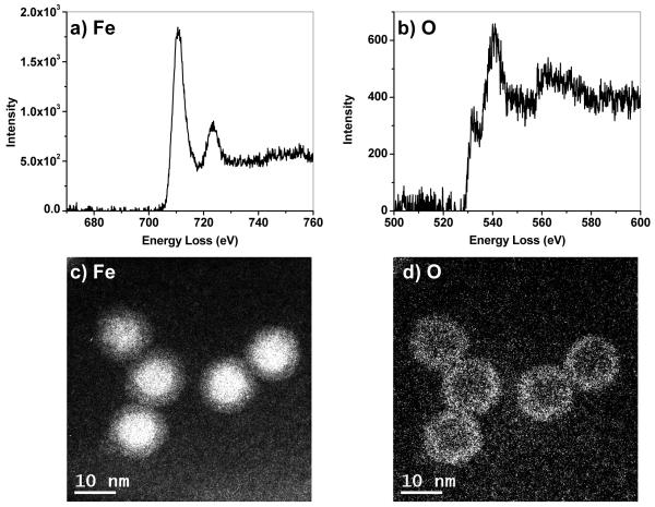
Monodisperse core–shell Fe@Fe3O4 nanoparticles were synthesized by the controlled oxidation of Fe nanoparticles with (CH3)3NO, based on the conditions described by Sun and coworkers.25,26 Two separate samples were prepared, one having a mean core diameter of 8.2 nm and overall diameter of 13.0 nm (Sample A, Figure 1), the other having a slightly larger core of 8.8 nm and an overall diameter of 13.8 nm (Sample B).23 An important modification in our synthesis is the oxidation of Fe nanoparticles with (CH3)3NO under an N2 atmosphere, which yields core–shell nanoparticles with a continuous interface. The boundary between the metallic core and oxide shell is still discernible by the change of contrast in the brightfield TEM image. HRTEM analysis (Figure 1, inset) reveals the Fe3O4 shell to be polycrystalline with domains in random orientations; the electron diffraction patterns produced by fast Fourier transform (FFT) analysis match the inverse spinel structure of iron oxide (Figure S1, Supporting Information). In comparison, the Fe core does not produce any characteristic diffraction peaks and appears to be amorphous, but its existence is supported by electron energy loss spectroscopy (EELS) and energy-filtered TEM (EFTEM) imaging (Figure 2). Elemental distribution maps of freshly prepared core-shell nanoparticles at the absorption edges of Fe (L2,3 edges at 708, 720 eV) and O (K edge starting at 530 eV) confirmed the Fe cores to be essentially unoxidized.
Figure 1.
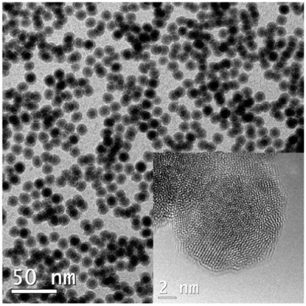
TEM and HRTEM images (inset) of core–shell Fe@Fe3O4 nanoparticles (sample A), with mean diameter of 13.0 nm (N=139, RSD = 5.5%). Core diameter and shell thickness are approximately 8.2 and 2.4 nm, respectively (N=40). See Supporting Information for size and structural analysis.
Figure 2.
(a,b) Electron energy loss spectra (EELS) near Fe and O edges. (c,d) Energy-filtered TEM images of core–shell nanoparticles using Fe and O edge values (708 and 530 eV, respectively).
Because it is difficult to distinguish γ-Fe2O3 from Fe3O4 by electron diffraction due to their similar lattice structures,27 we converted core–shell nanoparticles into hollow nanoshells by extending the reaction time (see Experimental Section). The optical absorption spectra of these hollow iron-oxide nanoparticles were compared with hollow nanoparticles produced by air oxidation, and also with polycrystalline, hollow γ-Fe2O3 nanoparticles produced by a different method described by Cabot et al 15 (Figures S2–S4, Supporting Information). The latter two both exhibit a broad peak near 450 nm, suggesting that the hollow nanoparticles produced by air oxidation are comprised of γ-Fe2O3. In contrast, the pristine hollow nanoparticles produced by (CH3)3NO oxidation do not exhibit this absorption peak, and support their structural assignment as Fe3O4.26 In addition, colloidal γ-Fe2O3 can be converted to α-Fe2O3 when heated to 500 °C, but the freshly prepared hollow Fe3O4 nanoparticles did not undergo such phase changes when annealed at this temperature (Figure S5, Supporting Information). We presume the oxide composition of the core–shell and hollow Fe3O4 nanoparticles to be very similar, as they share a common reaction condition.
Exchange bias in core–shell nanoparticles
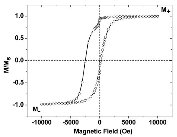
Core–shell Fe@Fe3O4 nanoparticles (Samples A and B) were dispersed in a weakly diamagnetic matrix of dimethyldioctadecylammonium bromide (DDAB), and characterized at low temperatures by superconducting quantum interference device (SQUID) magnetometry using a cooling field of +10 kOe. These particles are superparamagnetic at room temperature but experience a large shift in magnetic hysteresis at 5 K. Sample A produced an exchange-bias field HE of 1150 Oe and a coercivity HC of 1330 Oe (Figure 3), effectively reproducing earlier measurements taken from Sample B, whose nanoparticles were of nearly equal size (Table 1).23 The large exchange-bias fields and coercivities are also accompanied by small but measureable moments aligned in the direction of the cooling field, most of which can be attributed to frozen spins at the core–shell interface. The net moment of frozen spins can be quantified as Mf= (M+ + M−)/2, where M+ and M− are the saturation magnetization in the positive (along the cooling field) and negative field directions, respectively. The magnetization values at maximum applied field (±10 kOe) can serve as M+ and M− to the first degree of approximation for any given sample. The relative magnitude of the frozen moment Mf/M+ is 0.33% for Sample A and 0.66% for Sample B (Table 1). We note that the Mf value calculated by this procedure is smaller than the value derived previously using the difference of the ZFC and FC magnetization curves under a high field,23 as the applied magnetic field is not reversed in that case.
Figure 3.
(a) Magnetic hysteresis of core–shell Fe@Fe3O4 nanoparticles at 5 K under FC (+10 kOe). Studies were conducted on a 1 wt% dispersion of particles in a DDAB matrix (Sample A).
Table 1.
Magnetic properties of core–shell Fe@Fe3O4 nanoparticles at 5 K, after field coolinga
| Sample A | Sample Bb | |
|---|---|---|
| dcore (nm) | 8.2c | 8.8 |
| tshell (nm) | 2.4c | 2.5 |
| HE (Oe) | 1150 | 1190 |
| HC (Oe) | 1330 | 1100 |
| Mf/M+ d | 0.33% | 0.66% |
| ΔM/M+ e | 12% | 31% |
Measurements performed on a 1 wt% dispersion of particles in a DDAB matrix with a +10 kOe cooling field, and collected after a single hysteresis cycle.
Ref. 23.
Size analysis based on particles in Figure 1 (see Supporting Information for details).
M+ = initial saturation magnetization along the cooling field; equivalent to MS.
Low-field jump ΔM defined as the sharp decrease in magnetization between +200 and −200 Oe.
In addition to a sizable HE and HC, a sudden jump in magnetization at low field (+200 to −200 Oe, Figure 3) can be observed under FC conditions. The low-field jump (quantified as ΔM/M+) is caused by magnetic switching in the polycrystalline shell, and can be attributed to the reduction of the Zeeman energy of the ferrimagnetic Fe3O4 domains in the shell layer at low field strength.23 When this energy becomes less than the magnetocrystalline anisotropy of individual domains, many of the ferrimagnetic domains can suddenly switch their orientations from the applied field direction to their respective easy axes (Figure 4). While most of the field-induced anisotropy can be attributed to frozen spins at the core–shell interface, it should be noted that uncompensated spins on the surface and in the shell layer can also be pinned into alignment under FC conditions and contribute toward unidirectional anisotropy. This surface pinning effect has been investigated recently in hollow nanoparticles comprised of γ-Fe2O3, supported by Monte Carlo simulations.16
Figure 4.
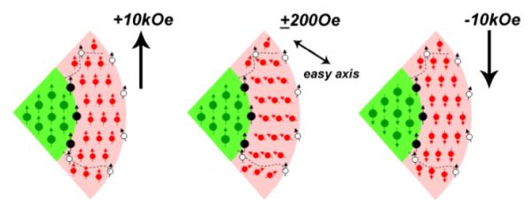
Cutaway (micromagnetic) view of spin configurations in a core–shell nanoparticle during a field sweep under FC conditions. Filled circles (green, red, and black) represent magnetic moments in the FM core, ferrimagnetic shell, and core–shell interface, respectively. For simplicity, each ferrimagnetic domain in the shell layer is represented as a spin lattice with a net moment. Dashed lines demarcate the boundaries of crystalline domains within the shell layer, and open circles indicate residual (uncompensated) spins at the surface or domain boundaries.
The HE, HC, and ΔM/M+ values obtained under FC conditions are all enhanced relative to measurements under zero-field cooling (not shown), as a result of magnetic exchange bias.23 However, the magnitude of the low-field jump does not correlate strongly with HE and HC, as it is also sensitive to structural factors such as the size of the ferrimagnetic Fe3O4 domains, the volume ratio of the core and shell layers, and variations in the shell oxide composition, as well as the stochastic nature of thermally activated processes in finite systems. For example, the conditions used to prepare Fe@Fe3O4 nanoparticle samples in our previous study (Sample B) are essentially identical to that of Sample A, but the percentage of shell moments participating in the low-field jump is more than double (Table 1).
Training effects
The primary role of frozen spins on the EB behavior of this system implies that EB effects are easily modulated by external parameters with a direct impact on Mf, such as temperature and cooling field strength.23 Another mechanism for varying Mf and measuring its influence over EB effects is to apply the hysteresis loop measurement repeatedly over multiple cycles at the same temperature, a process known as magnetic training. The training effect on EB have been previously observed in core–shell Fe@Fe-oxide nanoparticles prepared by cluster-beam condensation methods and analyzed as compact powders,17,28,29 but not been thoroughly studied for nanoparticles isolated and dispersed in a diamagnetic matrix.
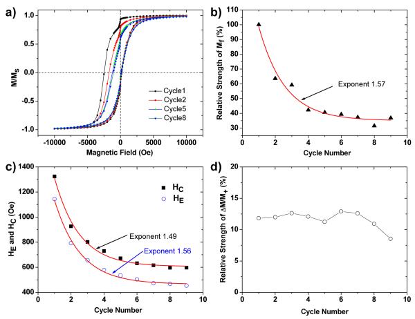
Freshly prepared core–shell Fe@Fe3O4 nanoparticles (Sample B) were cooled to 5 K under a field of +10 kOe, then subjected to nine consecutive M–H hysteresis cycles (Figure 5a). The population of aligned frozen spins was observed to decay exponentially with cycle number: the Mf/M+ ratio decreases to 37% of its initial value after 9 cycles, corresponding to a relaxation constant of 1.57 (Figure 5b). The exchange-bias field HE and coercivity HC also decay exponentially with the number of hysteresis cycles, with decay constants of 1.56 and 1.49, respectively (Figure 5c). However, the relative intensity of the low-field jump (ΔM/M+) is not strongly affected by the number of training cycles (Figure 5d), in line with our observations above.
Figure 5.
Training effect on exchange bias in core–shell nanoparticles (Sample B). (a) Changes in the magnetic hysteresis loop of dispersed Fe@Fe3O4 nanoparticles over multiple measurement cycles. For clarity, only data from cycles 1, 2, 5, and 8 are shown. (b) Relative decrease in Mf as a function of cycle number (from an initial Mf/M+ ratio of 0.33%). (c) Decrease in HC and HE as a function of cycle number. Exponential curve fits in (b) and (c) indicated by solid lines. (d) The relative intensity of the low-field demagnetization (ΔM/M+) is insensitive to the number of measurement cycles.
The decay exponent of HC is less than that of HE, and indicates some differences in the generation of exchange anisotropy versus coercivity. According to the classic Meiklejohn–Bean model for exchange bias, HE is proportional to the strength of unidirectional exchange coupling, which can be expressed as:
| (1) |
where n/a2 is the density of exchange-coupled bonds across the core–shell interface (i.e. number of frozen interfacial spins per unit area), Jex is the interfacial exchange constant, SFM and SFI represent individual spin moments in the ferromagnetic and ferrimagnetic layers, respectively, and MFM and tFM are the saturation magnetization and effective thickness of the ferromagnetic layer (for the case of a spherical Fe core of diameter DFM , tFM is approximately 1/6 DFM).1 This implies a direct relationship between the population of frozen spins and the strength of exchange coupling between core and shell moments, and is supported by the nearly identical decay constants of HE and Mf/M+. A similar conclusion was reached by Zheng et al., who examined training effects on HE in Fe@γ-Fe2O3 nanoparticles.28 Coercivity, on the other hand, is not solely influenced by the unidirectional alignment of frozen spins. This can be explained by considering the decay mechanism, in which a small fraction of frozen spins are depinned from their initial alignment and canted in off-axis directions with each measurement cycle. Although these “melted” spins no longer contribute toward the exchange-bias field, they are still exchange-coupled with both shell and core moments and can therefore contribute to coercivity, resulting in a slightly different decay constant for HC.
Aging effects
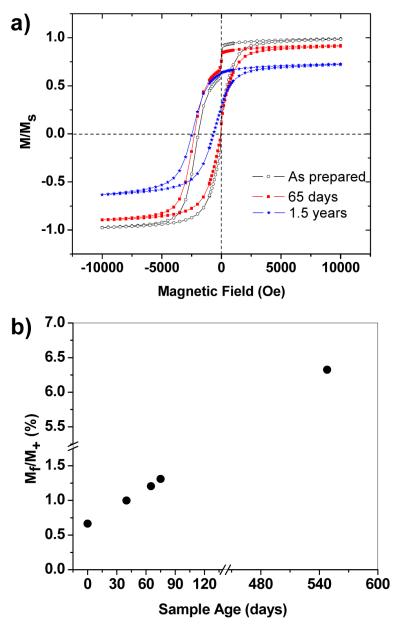
The magnetic properties of the Fe@Fe3O4 core–shell nanoparticles in a DDAB matrix slowly change over time when stored in a capped vial and kept at ambient conditions. Magnetic measurements of Sample B at 5 K over a 1.5-year period indicate a gradual disappearance of the low-field jump (ΔM/M+) and a 25% loss in saturation magnetization; however, HC remains large and HE slightly increases over time (Figure 6a). Most remarkably, we observe a dramatic increase in the relative percentage of Mf to more than 6% after 1.5 years (Figure 6b). These effects were confirmed by the analysis of multiple Fe@Fe3O4 samples, all of which exhibit variable rates of change with age.
Figure 6.
(a) FC hysteresis loops of Fe@Fe3O4 nanoparticles immediately after sample preparation (open circles), after 65 days (filled red squres), and after 1.5 years (blue stars). (b) Increases in Mf over time.
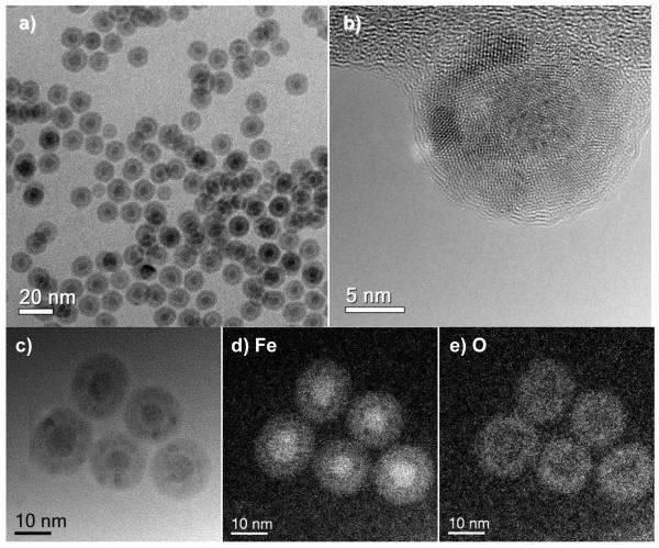
Although the age-related oxidation produces a considerable increase in the population of frozen spins, it is not accompanied by a commensurate increase in HE, in contrast to our earlier observations of correlated changes with cooling field and temperature,23 and also through the training effect in a freshly made sample as described above. This discrepancy is the result of complex changes in the structure and chemical composition of core–shell nanoparticles due to air oxidation, as shown by a careful TEM analysis of the nanoparticles recovered from the DDAB matrix. We observed the cores of the aged nanoparticles to have shrunk from an average diameter of 8.8 nm to less than 6 nm, whereas the shell thickness has increased by at least 2 nm, resulting in an overall expansion in particle volume (Figure 7a,b). However, elemental mapping by EFTEM analysis with 2-nm resolution indicate that the Fe cores are essentially unoxidized, with the O signal strongest in the shell region (Figure 7d,e).
Figure 7.
Fe@Fe3O4 nanoparticles after 1.5 years of storage in a DDAB matrix. (a,b) TEM and HRTEM images; (c–e) brightfield and EFTEM images, indicating Fe and O distribution.
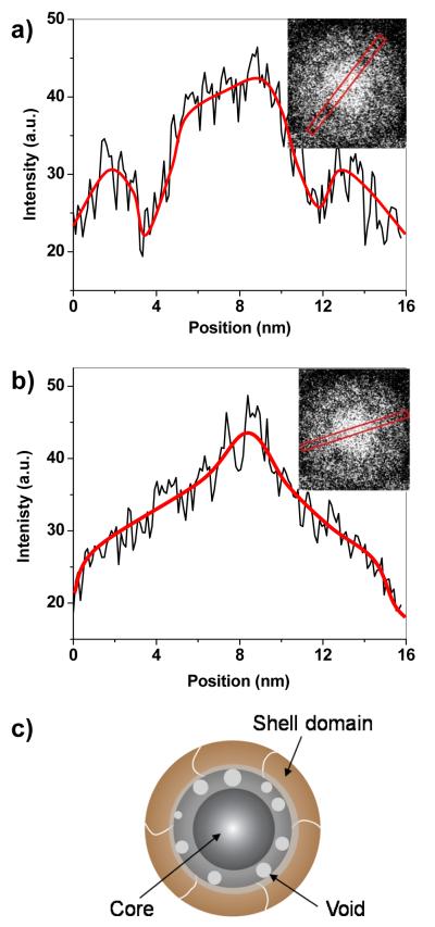
The aged nanoparticles exhibit greater contrast at the core–shell interface in the brightfield TEM images (Figure 7a–c), initially suggestive of a “yolk–shell” structure with a detached core and shell. However, a careful profiling of the nanoparticle in the EFTEM image for Fe distribution indicates that the core–shell interface is in fact mostly intact, but with some small (≤2 nm) voids formed between layers (Figure 8a,b). This structural evolution can be attributed to the nanoscale Kirkendall effect, in which the oxidation-driven migration of metal atoms from the core to the shell produces vacancies at the interface that gradually coalesce into voids.30,31 The Kirkendall effect is generally considered a mechanism for metallurgical corrosion, but has been utilized recently for transforming nanoparticles into yolk–shell and hollow nanostructures.15,26,31,32,33,34,35,36,37
Figure 8.
High-resolution structural analyses of an aged core–shell nanoparticle, taken from the EFTEM image for Fe distribution (cf. Figure 7d). (a) Line profile intersecting two voids; (b) line profile across a continuous core–shell interface. Lines in intensity plots are drawn to guide the eye. (c) Structural model of an air-oxidized core–shell nanoparticle, with an interstitial porous oxide layer.
The high-resolution TEM and EFTEM analyses indicate that the air-oxidized nanoparticles still have a ferromagnetic Fe core and a polycrystalline ferrimagnetic shell (Fe3O4 or γ-Fe2O3), but the well-defined interface has been replaced by a porous and amorphous iron-oxide layer having a thickness of roughly 2 nm (Figure 8c). Exposure to ambient conditions is well known to oxidize Fe and Fe3O4 into γ-Fe2O3 and other iron oxides with weak magnetic properties, so it is remarkable that the Fe core is well preserved after a 1.5-year exposure, as confirmed by EFTEM imaging and SQUID magnetometry. The reduction in core size indicates that Fe oxidation did occur, but the resulting oxide layer and possibly the surrounding DDAB matrix stabilized the Fe core from further degradation at room temperature. The exact composition of this intermediate oxide is presently unclear, as it is mostly amorphous and lacks a characteristic lattice structure, but it is reasonable to propose that its composition may be comparable to FexO (x ≤ 1), with an oxidation state intermediate to that of the Fe core and the iron-oxide shell. It is worth mentioning that FeO is known to disproportionate into Fe and Fe3O4, 27,38 and may possibly provide a buffer against ambient oxidation. We note that the aged nanoparticles were converted uniformly into hollow crystalline nanoshells upon thermal annealing at 400 °C under argon (Figure S6, Supporting Information).
The structural model proposed above is in accord with the observed magnetic behavior of the aged core–shell sample (Figure 6), and allows us to assign the interstitial oxide layer as the main source of additional frozen spins. In principle, a dense frozen spin layer and reduction in core size (dFM) should strengthen exchange anisotropy; however, we observe only a slight increase in HE (Figure 6a). There are at least two reasons that can explain this discrepancy. First, the core–shell interface is only semi-continuous, so the exchange coupling is weakened by the presence of voids. Second, exchange coupling is a short-range interaction and decays exponentially over distance,1 so the increased numbers of frozen spins away from the core–shell interface might not proportionally enhance exchange coupling between the core and shell domains. It is also worth considering that the glassy spin layer itself may provide a significant source of exchange anisotropy, as has been demonstrated in a thin-film bilayer system.7 The disappearance of the low-field jump with age is most likely related to changes in the shell layer, as the increase in shell thickness appears to be accompanied by growth of the crystalline shell domains. An increase in domain size would support a larger magnetocrystalline anisotropy barrier, and diminish the spontaneous low-field switching of the shell moments from the cooling field direction to their easy axis.
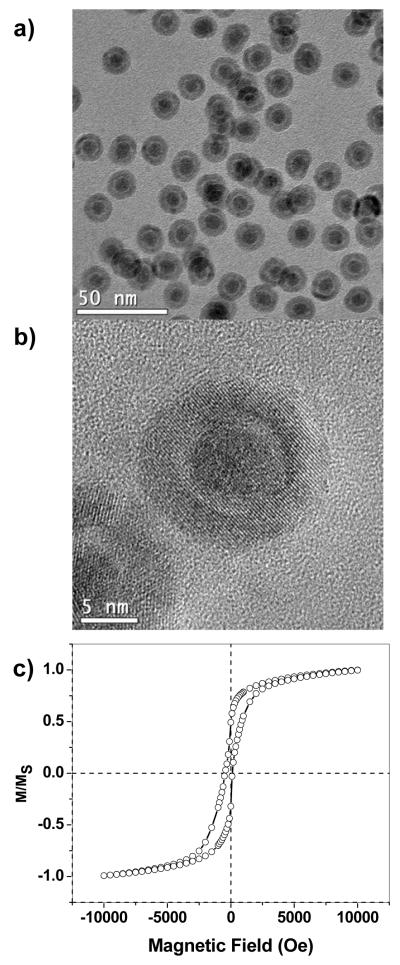
Lastly, in order to determine the extent to which exchange bias is affected by oxidation-dependent structural changes, we compared the magnetic behavior of the aged core–shell nanoparticles against freshly prepared yolk–shell Fe@Fe3O4 particles, which were prepared by the treatment of Fe nanoparticles with (CH3)3NO with exposure to air (See Experimental section). TEM analysis of these nanoparticles initially suggests a very similar morphology as the aged core–shell nanoparticles, but a closer inspection using HRTEM reveals a distinct gap between core and shell, indicating further progression of the Kirkendall effect (Figure 9a,b). SQUID analysis of the yolk–shell Fe@Fe3O4 particles at 5 K under FC conditions established a drastic reduction in HC and HE, indicating a nearly complete decoupling of the Fe core from the Fe3O4 domains in the shell layer (Figure 9c). Therefore, the breaking point in EB coupling for core–shell nanoparticles is determined by a physical separation of core and shell.
Figure 9.
Structural analysis and magnetization behavior of freshly prepared yolk–shell Fe@Fe3O4 nanoparticles. (a,b) TEM and HRTEM analysis; (c) magnetic hysteresis measurements at 5 K under FC (+10 kOe). Studies were conducted on a 10 wt% dispersion of particles in a DDAB matrix.
In closing, we have demonstrated that EB effects in magnetic core–shell nanoparticles can be remarkably robust, despite age-related changes in chemical and physical structure. This is primarily supported by a small but significant number of aligned frozen spins between the core and shell layers, whose relative population can increase over time and with changes in chemical composition. The frozen spin population is also influenced by physical parameters such as temperature and applied field strength, providing mechanisms to tune the strength of exchange anisotropy with subsequent control over magnetic switching behavior. Our studies strengthen the growing body of evidence that uncompensated frozen spins, including those in spin glass systems,7 can support EB effects in multilayered magnetic nanostructures.
Supplementary Material
Acknowledgments
This work is supported by the National Science Foundation under CHE-0957738, and the National Institutes of Health under RC1 CA-147096. Work at the Center for Nanoscale Materials was supported by the U. S. Department of Energy, Office of Basic Energy Sciences, under Contract No. DE-AC02-06CH11357. We thank M. Bode for fruitful discussions.
Footnotes
Supporting Information available: TEM images and size analysis, electron diffraction analysis, and optical absorption spectra of hollow Fe3O4 and γ-Fe2O3 nanoparticles; additional magnetic measurements of Fe@Fe3O4 nanoparticles as a function of time. This data is available free of charge via the Internet at http://pubs.acs.org.
References
- 1.Nogués J, Sort J, Langlais V, Skumryev V, Suriñach S, Muñoz JS, Baró MD. Phys. Rep. 2005;422:65–117. [Google Scholar]
- 2.Nogués J, Schuller IK. J. Magn. Magn. Mater. 1999;192:203–232. [Google Scholar]
- 3.Takano K, Kodama RH, Berkowitz AE, Cao W, Thomas G. Phys. Rev. Lett. 1997;79:1130–1133. [Google Scholar]
- 4.Del Bianco L, Hernando A, Multigner M, Prados C, Sánchez-López JC, Fernández A, Conde CF, Conde A. J. Appl. Phys. 1998;84:2189–2192. [Google Scholar]
- 5.Tang YJ, Smith DJ, Zink BL, Hellman F, Berkowitz AE. Phys. Rev. B. 2003;67:054408. [Google Scholar]
- 6.Tracy JB, Bawendi MG. Phys. Rev. B. 2006;74:184434. [Google Scholar]
- 7.Ali M, Adie P, Marrows CH, Greig D, Hickey BJ, Stamps RL. Nature Mater. 2007;6:70–75. doi: 10.1038/nmat1809. [DOI] [PubMed] [Google Scholar]
- 8.Meiklejohn WH, Bean CP. Phys. Rev. 1956;102:1413–1414. [Google Scholar]
- 9.Meiklejohn WH, Bean CP. Phys. Rev. 1957;105:904–913. [Google Scholar]
- 10.Zabel H, Bader SD, editors. Magnetic Heterostructures. Springer; New York: 2007. [Google Scholar]
- 11.Malozemoff AP. J. Appl. Phys. 1988;63:3874–3879. [Google Scholar]
- 12.Mauri D, Siegmann HC, Bagus PS, Kay E. J. Appl. Phys. 1987;62:3047–3049. [Google Scholar]
- 13.Miltényi P, Gierlings M, Keller J, Beschoten B, Güntherodt G, Nowak U, Usadel KD. Phys. Rev. Lett. 2000;84:4224–4227. doi: 10.1103/PhysRevLett.84.4224. [DOI] [PubMed] [Google Scholar]
- 14.Ohldag H, Scholl A, Nolting F, Arenholz E, Maat S, Young AT, Carey M, Stöhr J. Phys. Rev. Lett. 2003;91:017203. doi: 10.1103/PhysRevLett.91.017203. [DOI] [PubMed] [Google Scholar]
- 15.Cabot A, Puntes VF, Shevchenko E, Yin Y, Balcells L, Marcus MA, Hughes SM, Alivisatos AP. J. Am. Chem. Soc. 2007;129:10358–10360. doi: 10.1021/ja072574a. [DOI] [PubMed] [Google Scholar]
- 16.Cabot A, Alivisatos AP, Puntes VF, Balcells L, Iglesias Ò, Labarta A. Phys. Rev. B. 2009;79:094419. [Google Scholar]
- 17.Del Bianco L, Fiorani D, Testa AM. J. Magn. Magn. Mater. 2007;310:2289–2291. [Google Scholar]
- 18.Skumryev V, Stoyanov S, Zhang Y, Hadjipanayis G, Givord D, Nogués J. Nature. 2003;423:850–853. doi: 10.1038/nature01687. [DOI] [PubMed] [Google Scholar]
- 19.Iglesias Ò , Batlle X, Labarta A. J. Phys. Condens. Matter. 2007;19:406232. doi: 10.1088/0953-8984/19/40/406232. [DOI] [PubMed] [Google Scholar]
- 20.Salazar-Alvarez G, Sort J, Suriñach S, Baró MD, Nogués J. J. Am. Chem. Soc. 2007;129:9102–9108. doi: 10.1021/ja0714282. [DOI] [PubMed] [Google Scholar]
- 21.Feygenson M, Yiu Y, Kou A, Kim K-S, Aronson MC. Phys. Rev. B. 2010;81:195445. [Google Scholar]
- 22.Inderhees SE, Borchers JA, Green KS, Kim MS, Sun K, Strycker GL, Aronson MC. Phys. Rev. Lett. 2008;101:117202. doi: 10.1103/PhysRevLett.101.117202. [DOI] [PubMed] [Google Scholar]
- 23.Ong QK, Wei A, Lin X-M. Phys. Rev. B. 2009;80:134418. [Google Scholar]
- 24.Egerton R. Electron Energy-Loss Spectroscopy in the Electron Microscope. Plenum Press; New York: 1996. [Google Scholar]
- 25.Peng S, Wang C, Xie J, Sun S. J. Am. Chem. Soc. 2006;128:10676–10677. doi: 10.1021/ja063969h. [DOI] [PubMed] [Google Scholar]
- 26.Peng S, Sun S. Angew. Chem. Int. Ed. 2007;46:4155–4158. doi: 10.1002/anie.200700677. [DOI] [PubMed] [Google Scholar]
- 27.Cornell RM, Schwertmann U. The Iron Oxides. VCH Publishers; New York: 1996. [Google Scholar]
- 28.Zheng RK, Wen GH, Fung KK, Zhang XX. J. Appl. Phys. 2004;95:5244–5246. [Google Scholar]
- 29.Peng DL, Hihara T, Sumiyama K, Morikawa H. J. Appl. Phys. 2002;92:3075–3083. [Google Scholar]
- 30.Birchenall CE. J. Electrochem. Soc. 1956;103:619–624. [Google Scholar]
- 31.Yin Y, Rioux RM, Erdonmez CK, Hughes S, Somorjai GA, Alivisatos AP. Science. 2004;304:711–714. doi: 10.1126/science.1096566. [DOI] [PubMed] [Google Scholar]
- 32.Wang CM, Baer DR, Thomas LE, Amonette JE, Antony J, Qiang Y, Duscher GJ. J. Appl. Phys. 2005;98:094308. [Google Scholar]
- 33.Latham AH, Wilson MJ, Schiffer P, Williams ME. J. Am. Chem. Soc. 2006;128:12632–12633. doi: 10.1021/ja064666q. [DOI] [PubMed] [Google Scholar]
- 34.Gao J, Zhang B, Zhang X, Xu B. Angew. Chem. Int. Ed. 2006;45:1220–1223. doi: 10.1002/anie.200503486. [DOI] [PubMed] [Google Scholar]
- 35.Henkes AE, Vasquez Y, Schaak RE. J. Am. Chem. Soc. 2007;129:1896–1897. doi: 10.1021/ja068502l. [DOI] [PubMed] [Google Scholar]
- 36.Railsback JG, Johnston-Peck AC, Wang J, Tracy JB. ACS Nano. 2010;4:1913–1920. doi: 10.1021/nn901736y. [DOI] [PubMed] [Google Scholar]
- 37.Zhai Y, Zhai J, Dong S. Chem. Commun. 2010;46:1500–1502. doi: 10.1039/b923466g. [DOI] [PubMed] [Google Scholar]
- 38.Redl FX, Black CT, Papaefthymiou GC, Sandstrom RL, Yin M, Zeng H, Murray CB, O’Brien SP. J. Am. Chem. Soc. 2004;126:14583–14599. doi: 10.1021/ja046808r. [DOI] [PubMed] [Google Scholar]
Associated Data
This section collects any data citations, data availability statements, or supplementary materials included in this article.


