Abstract
Insertion velocity, tip asymmetry, and shaft diameter may influence steerable needle insertion paths in soft tissue. In this paper we examine the effects of these variables on needle paths in ex vivo goat liver, and demonstrate practical applications of robotic needle steering for ablation, biopsy, and brachytherapy. All experiments were performed using a new portable needle steering robot that steers asymmetric-tip needles under fluoroscopic imaging. For bevel-tip needles, we found that larger diameter needles resulted in less curvature, i.e. less steerability, confirming previous experiments in artificial tissue. The needles steered with radii of curvature ranging from 3:4 cm (for the most steerable pre-bent needle) to 2:97m (for the least steerable bevel needle). Pre-bend angle significantly affected needle curvature, but bevel angle did not. We hypothesize that biological tissue characteristics such as inhomogeneity and viscoelasticity significantly increase path variability. These results underscore the need for closed-loop image guidance for needle steering in biological tissues with complex internal structure.
I. Introduction
Needle insertion into organs is associated with many common medical procedures, including biopsies, ablation, and brachytherapy. The effectiveness of a procedure can be decreased due to inaccurate needle placement, unexpected tissue deformation, and difficulty accessing targets due to anatomical obstacles. The goal of robotic needle steering is to solve these problems by allowing for controlled needle insertion and real-time correction of the needle’s direction inside tissue. In prostate brachytherapy, for example, pubic arch interference (PAI) is a condition in which a portion of an enlarged prostate is blocked by the pubic bone and cannot be reached with a straight needle [1]. PAI could disqualify the patient for brachytherapy, leaving more radical treatments as the only alternative. In hepatic (liver) treatments, needle steering is particularly promising for ablation and biopsy of tumors, in which accurate needle placement is critical.
Recently, researchers have developed techniques for needle steering and identified models for needle steering and needle-tissue interaction [2] [3] [4] [5] [6] [7] [8] [9]. Most needle steering studies have been performed in artificial tissue gels, e.g., [9] [10] [11], with few experiments in real tissues. Our group has characterized effects of insertion velocity and tip asymmetry in artificial tissues [10], and developed controllers, planners, and compensators to account for potential errors in insertion based on computational, modeling, and initial needle orientation errors [12].
We use a needle steering technique that incorporates flexible needle shafts with asymmetric tips. Forces applied normal to the surface of the asymmetric tip cause the needle to bend in the direction of the asymmetry. By simply inserting and rotating the needle shaft, needle steering can be achieved [8]. This work presents the effects of needle insertion design variables on needle shaft curvature in ex vivo biological tissue.
There are two other known examples of needle steering in ex vivo tissue. Minhas et al. tested the steering of a custom needle with a large stainless steel tip attached to a thin flexible Nitinol wire in cadaveric brain tissue [13]. They measured the error of reaching a desired target. A surgeon controlled the needle manually by adjusting the duty-cycled spinning and needle tip orientation of the needle. Burdette et al. [14] developed and tested an integrated steerable needle (using active cannulas) and ablative device. They demonstrate the use of the device for ablating ex vivo bovine liver. Our needle characteristics are different from those of these other studies, and our experiments consider the effects of needle parameters and a broader set of potential needle steering applications.
II. Portable Needle Steering Device
We have developed a portable needle steering device for the insertion and control of flexible needles in soft tissues (Fig. 1). Borrowing heavily from the existing needle steering robot at Johns Hopkins University [10], the portable system can insert and rotate a flexible needle, enabling needle steering. This is achieved though a rotational subassembly mounted on a linear slide. The linear slide is mounted on a manual pantograph mechanism which allows the entire stage to move vertically. Linear bushings and guides are used to maintain a level stage; however, some manual adjustments are needed due to backlash in the pantograph mechanism. This system was designed for portability and standardization, and consists of easily detachable subassemblies.
Fig. 1.
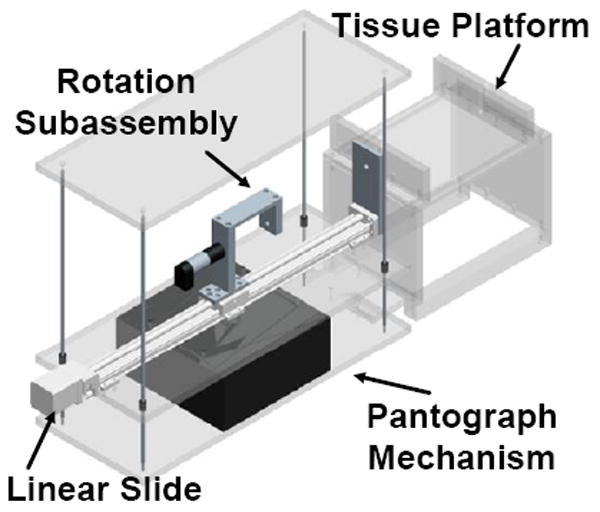
Model of the portable needle steering device.
The translational subsystem consists of the linear slide with limit switches, a 2-phase stepper motor, and a controller from Velmex, Inc. The controller communicates serially with a Lenovo ThinkPad laptop running Ubuntu Linux 9.04 via a serial-to-USB converter to receive motion commands and send position information. The rotational subsystem consists of a 12V DC Maxon motor, an encoder, and a power amplifier. The rotational motor is controlled via analog outputs from a PCMCIA National Instruments DAQcard-6024e, which also reads in position data from the encoders through an external quadrature clock converter chip. This device is controlled using existing software developed for the non-portable needle steering system, and uses the CISST software libraries [15] for many functions.
III. Experimental Methods
A series of experiments were performed on goat liver to identify the effects of insertion velocity, needle tip asymmetry, and shaft diameter on shaft curvature. Fluoroscopic (x-ray) images were taken before and after insertion using a 9-inch XRII OEC series 9600 fluoroscope (Fig. 2).
Fig. 2.
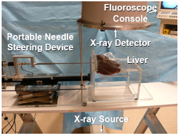
Image of experimental setup, including the portable needle steering device, the fluoroscope, and the liver.
A. Tissue Choice and Insertion Zone Identification
Fresh ex vivo goat liver was chosen as the biological tissue for these experiments. The liver has a complex internal structure consisting of blood vessels and bile ducts, surrounded by hepatocytes, and ligaments that separate the liver into various lobes. Preliminary experiments showed that these structures can compromise steerability. Therefore, we used CT scans to identify and avoid these regions as much as possible. The three-dimensional (3D) Slicer software package was used to render a volume from the scans, and thresholding parameters and cropping were employed to identify larger internal structures. Based on these models, an insertion zone with the most homogeneous tissue was chosen to avoid insertion complications (Fig. 3).
Fig. 3.
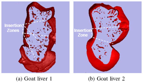
Slices of volume-rendered goat livers generated using fluoroscopic images and 3D Slicer software.
B. Needle Selection and Fabrication
The needles used in these experiments were made out of superelastic Nitinol, which was chosen for its flexibility and resistance to plastic deformation. Two types of needle tip asymmetries were tested in these experiments: bevel tip and pre-bent tip (Fig. 4). Bevel-tip needles have a single angled tip, while pre-bent needles have a bent section in the vicinity of the tip, which can also be beveled. Bevel tips were hand-ground using ISO 6344 standard 320, 400, and 600-grit sandpaper, and a custom fixture was used to hold the needle shaft at a particular angle. Pre-bent needles were also formed by hand, first by grinding a bevel tip. Pliers were used to grasp approximately 3 mm of the shaft and the tip was bent so that the angle of the bend was in line with the bevel angle. Due to errors inherent in machining needle tips by hand, all needles were inspected and measured using a Mitutoyo Toolmaker’s microscope (Table I).
Fig. 4.
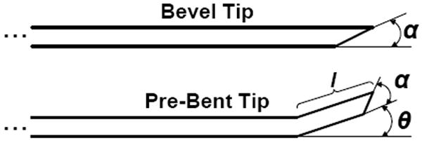
Bevel-tip needles have a single angled tip defined by the variable α. Pre-bent needles are characterized with a bend angle, θ, and bend length, l. Pre-bent needles may also have bevel angles.
TABLE I.
Needle Tip Measurements
| Diameter | Tip | Parameter | Values for 5 needles | ||||
|---|---|---|---|---|---|---|---|
| 0.74 mm | Bevel | α (deg) | - | - | 43.5 | - | - |
| 0.58 mm | Bevel | α | 11.0 | 27.5 | 45.0 | 56.0 | 79.0 |
| Bent | θ (deg) | 8.0 | 16.0 | 34.0 | 42.0 | 56.0 | |
| α | 43.5 | 42.0 | 45.0 | 44.0 | 45.0 | ||
| l (mm) | 3.45 | 3.69 | 4.92 | 3.25 | 3.73 | ||
| 0.48 mm | Bevel | α | 9.0 | 28.0 | 46.0 | 59.0 | 79.0 |
| Bent | θ | 8.0 | 15.0 | 22.0 | 35.0 | 58.0 | |
| α | 46.0 | 44.5 | 44.0 | 42.0 | 42.0 | ||
| l | 3.49 | 3.28 | 4.13 | 3.88 | 4.66 | ||
| 0.38 mm | Bevel | α | - | - | 46.0 | - | - |
C. Needle Insertion Angle Calibration
To facilitate image interpretation, needle bending in the horizontal plane was desired. The bending plane of the needle depends on the orientation of the needle about the axis of the needle shaft. Bevel-tip surfaces must be orthogonal to the surface plane and pre-bends must lie in the plane to keep the needle shaft in the plane. Small deviations in orientation will cause the needle to move vertically in the tissue during insertion. The needle insertion angle was calibrated using the method from [10]. The needle was manually aligned prior to insertion, deviations from the plane were observed in trial insertions, and the angle was modified accordingly. This method, by its manual nature, can introduce error into the estimation of final tip positions and curvature. A planar controller has been developed to minimize this error [12]. However, this method requires the use of stereo or 3D images, which was not possible with the single plane fluoroscope available for these experiments.
D. Obtaining Needle Coordinates from Fluoroscopic Images
The images obtained from the fluoroscope, and used for these experiments, are warped due to internal factors associated with the x-ray detector and external factors such as surrounding magnetic fields. Due to the geometric nature of our analysis, distortion-free images are critical. Therefore, we used an image rectification and calibration technique to correct the images [16]. By imaging an object with known dimensions, we were also able to obtain a pixel-to-millimeter scaling factor, which is a reasonable approximation since the steering occurs in a plane parallel to the detector and the radiation cone is small.
The images were segmented in order to determine the locations of the needle shaft and the needle tip. First, a combination of background subtraction, conservative pixel value thresholding, and smoothing was applied to prepare the images for processing. This resulted in images with large lengths of visible needle shaft and also large regions of visible liver deformation. Pixel values are:
A previously developed kinematic model [8] was used to construct an algorithm to intelligently search for the needle in the images. Previous work determined that circular arcs describe the steering trajectory of bevel-tip needles within a plane [17]. These experiments assume that the needle is steering in a plane parallel to the x-ray detector, which projects to a circle in the images. Therefore, segmenting a bevel-tip needle in an image can be reduced to fitting a circular arc to the image. This approach is similar to the method used in [6], but the algorithm presented below does not use least squares and is relatively robust to the initialization parameters and regions of large liver deformation.
The algorithm is initialized with three pixel locations: the approximate location of the needle base, Bn; the needle tip, Tn; and some pixel on the needle shaft between the tip and the base. A sub-pixel corner finder precisely locates the needle base and the needle tip. The third point is used to approximate the radius, Rn, of a circular arc connecting the needle base and needle tip and to approximate the needle’s concavity, Sn. Using these arc parameters, a simulated needle image was generated:
The arc is thickened so that its width in pixels is approximately equal to the width of the needle in the x-ray images. The correlation between the simulated image and circular structure in the x-ray images can be quantified by:
which penalizes the length of an arc describing the needle, ensuring that the arc stops at the tip of the needle and does not attempt to characterize the motion of the tissue near the tip. The task of segmenting the needle in the image can now be stated as
which can be solved with Matlab’s simplex optimization search (fminsearch) initialized using the approximate arc parameters previously determined.
E. Experimental Variables
Two main experimental variables were considered: insertion velocity and tip asymmetry. Three insertions in two different goat livers were performed for each experiment.
1) Experiment 1 – Insertion Velocity
Needles were inserted 10 cm at five velocities: 0.5 , 1.0 , 1.5 , 2.0 , and 2.5 cm/s. Each needle had a 45° bevel angle at the tip. Four needle diameters were tested: 0.38 , 0.48 , 0.58 , and 0.74mm.
2) Experiment 2 – Tip Asymmetry
The effects of tip asymmetry were studied by varying the degree of asymmetry of the needle tip and by inserting needles 10 cm at 1:5 cm/s. Two types of needle tip asymmetry were used: bevel-tip and pre-bent tip. The following nominal bevel angles were used: 10°, 30°, 45°, 60°, and 80°. The pre-bent needles each had a nominal 45° bevel at the tip and had a nominally 5°, 15°, 30°, 45°, or 60° bent section approximately 3mm long. Two needle diameters were tested: 0:58mm and 0:48mm. Table I provides actual dimensions for the needles, which differ from the nominal values.
IV. Results and Discussion
A. Experiment 1: Insertion Velocity
The effect of insertion velocity on final needle shaft shape is demonstrated using curvature measurements (Fig. 5). A Kruskal-Wallis test was used to determine the significance of the effects of diameter, tip asymmetry, and insertion velocity on needle curvature. This test is appropriate for distributions with a large number of outliers, as is the case with our data. However, we note that the Kruskal-Wallis test (and most standard tests, including analysis of variance) has limited modeling power due to the inhomogeneity of variance seen in our data, found using Bartlett’s multiple-sample test for equal variance. As shown in Table II, the Kruskal-Wallis test for the insertion velocity experiment shows significant differences between the diameter groups, but not velocity or liver sample. A p-value of less than 0.05 indicates a group has statistically significant differences. To further identify which groups were significantly different from others, a post-hoc Scheffe Test was done using the Kruskal-Wallis statistic. For the four diameters tested, each diameter was significantly different from all the other diameters except for adjacent levels (e.g., 0:74mm and 0:58mm).
Fig. 5.
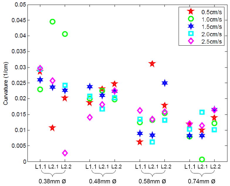
Effects of insertion velocity on shaft curvature for four different shaft diameters and three different insertions in two livers (one insertion into Liver 1 (L1.1) and two insertions into Liver 2 (L2.1, L2.2)).
TABLE II.
Kruskal-Wallis p-values for Curvature
| Source | Insertion Velocity | Bevel Tip Asymmetry | Bent Tip Asymmetry |
|---|---|---|---|
| Diameter | 0.0000 | 0.2058 | 0.5476 |
| Velocity | 0.9938 | - | - |
| Tip Angle | - | 0.0914 | 0.0019 |
| Liver | 0.6048 | 0.5379 | 0.0107 |
These results confirm models and previous experiments in artificial tissues, showing that curvature decreases as diameter increases. Increased stiffness of the needle dominates over the effect of a larger bevel or pre-bent surface. The lack of statistical significance between the two liver samples is also promising; if needles behave similarly in relatively homogeneous regions of liver from two different animals, we might also see such consistency across patients.
B. Experiment 2: Tip Asymmetry for Bevel-Tip Needles
The effect of bevel angle on curvature for various needle insertions was also studied (Fig. 6). We calculated the significance of diameter, bevel angle, and liver using Kruskal-Wallis tests, as shown in Table II. Similar to Experiment 1, the applicability of standard tests is compromised by inhomogeneous variance. There are no clear significant differences between any of the groups, so post-hoc tests do not apply.
Fig. 6.
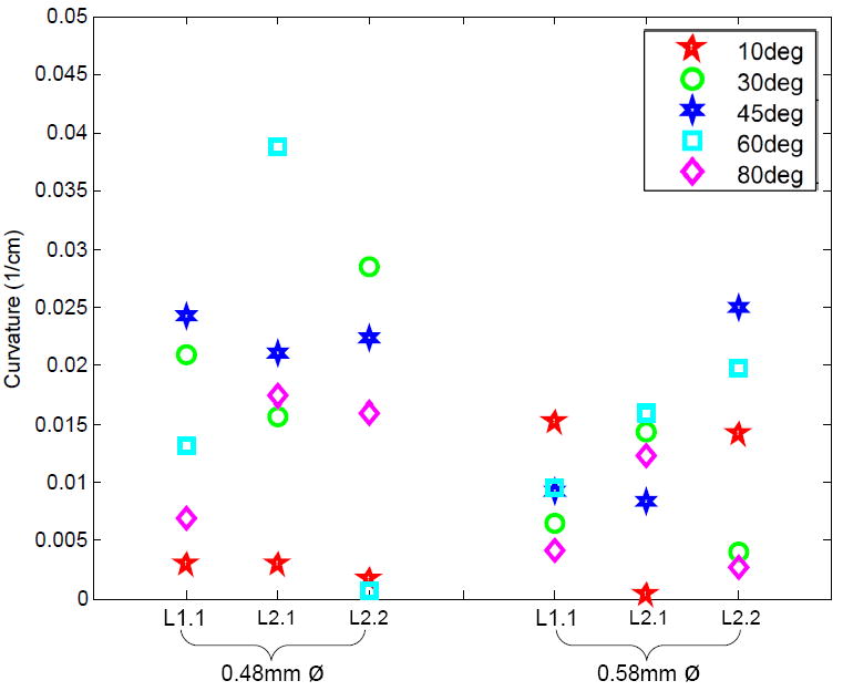
Effects of bevel-tip angle (α) on shaft curvature for two different shaft diameters and three different insertions in two livers (one insertion into Liver 1 and two insertions into Liver 2).
The lack of significance of bevel angle can explained by tissue inhomogeneity, which results in increased variance. Specifically, changing the bevel angle does not increase the surface area/direction of the cutting tip enough to produce the forces necessary to cut though though membranes and vessels without causing deviation from the expected path.
C. Experiment 2: Tip Asymmetry for Bent-Tip Needles
The effect of bent-tip angle on curvature is shown in Fig. 7. We calculated the significance of diameter, bend angle, and liver using the Kruskal-Wallis test, as shown in Table II. In this case, there was homogeneous variance between diameter groups. There was a significant effect of bend angle and liver sample, but not for diameter. As with Experiment 1, to further identify which groups were significantly different from others, a post-hoc Scheffe Test was done using the Kruskal-Wallis statistics to indicate which angle groups were significantly different. There is a significant difference between the groups with a nominal bend angle of 5° and those with a nominal angle of 45°. The other angle groups fall within the mean ranks of the other angles, so they are not significantly different than the rest.
Fig. 7.
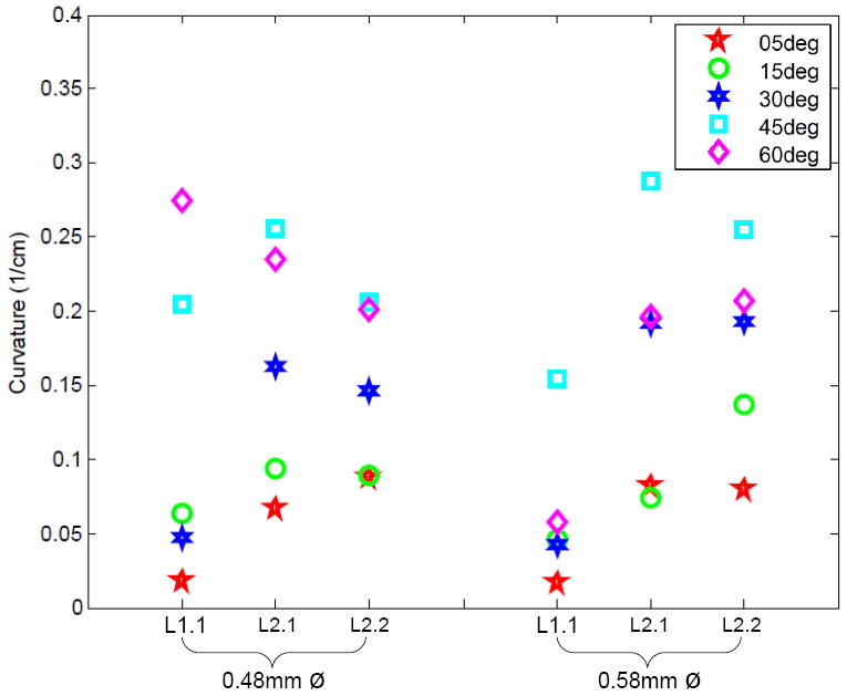
Effects of pre-bent tip angle (θ) on shaft curvature for two different shaft diameters and three different insertions in two livers (one insertion into Liver 1 and two insertions into Liver 2).
Although tip asymmetry did change the path of the needle, we expected significance between more groups. We hypothesize that this is because needles with very large tip asymmetries (e.g., 60°) are exposed to greater tip forces, which increase the variance and curvature of the needle paths. Due to the larger amount of curvature exhibited by the pre-bent needles, they likely left the homogeneous regions of the livers that were selected for these experiments. Consequently, the liver-specific tissue inhomogeneities may have resulted in the statistical significance between livers. These results indicate the need for patient-specific organ models for clinical needle steering.
V. Towards Clinical Applications of Needle Steering
To demonstrate the potential clinical applications of a needle steering robot, three common needle-based medical procedures were simulated in ex vivo tissue: ablation, biopsy, and brachytherapy.
For the ablation experiment, the needle was inserted to a specific location and then partially retracted and reinserted three more times with different tip orientations to demonstrate coverage of a region of interest. One way to perform ablation is to make the needle itself an ablator. A protective sheath/cannula would need to be passed over it in order to protect the surrounding tissue. Such a sheath can have higher structural stiffness than the steerable needle; this would deform the tissue but would not displace the tip relative to the tissue. This method is similar to that used in [14]. A second method is to deploy a cannula over the steerable needle, remove the needle, and then insert an ablator via the cannula. Finally, a catheter ablator could be used. Catheter ablators are often used in cardiac ablation procedures in which the flexible, hollow catheter is passed over a guidewire intravenously to ablate a targeted region of the heart. In the case of ablation within an organ, a steerable needle can be steered to the targeted tissue and can act like a guidewire for the catheter ablator. A commercial ablator was not available for this experiment, so we merely show a hypothetical ablation of a region of interest. The diameter of the ablation zone in Fig. 8 is based on an estimate for a typical radiofrequency catheter ablator, heating for 5 minutes [18]. There are several factors which affect the volume of ablated tissue including time, frequency, and blood flow.
Fig. 8.
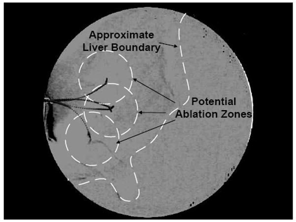
Simulated ablation was performed in ex vivo liver as an example of a needle steering application. The steered needle was partially inserted and retracted several times with different tip orientations to demonstrate coverage of a region of interest.
For the biopsy and brachytherapy examples, the robot was used to steer the needle to a specific target from a pre-defined insertion location. For the biopsy example, the target was an artificial tumor made out of hydrocolloid dental impression material impregnated with iron filings. For the brachytherapy example, there were three desired targets spaced roughly 1:0 cm apart. Once the needle was at the desired target location, a teflon sheath was passed over the needle and then the needle was removed from the tissue. Under x-ray guidance, standard biopsy and brachytherapy tools were introduced into the sheath. The biopsy was performed using an 20-gauge biopsy gun (Fig. 9). The brachytherapy was performed with a standard 20 gauge needle and the seeds were 1mm-diameter, 5mm-long pieces of stainless steel wire which is representative of typical radioactive seed dimensions (Fig. 10).
Fig. 9.
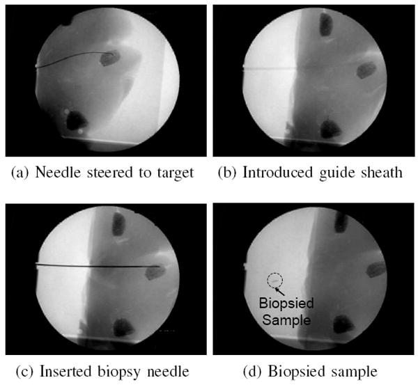
Biopsy was performed in ex vivo liver as an example of a needle steering application. The steered needle was used to deploy a sheath that was then used to introduce a conventional biopsy gun.
Fig. 10.
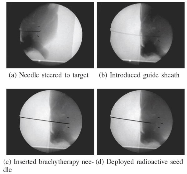
Brachytherapy was performed in ex vivo liver as an example of a needle steering application. The steered needle was used to deploy a sheath that was then used to introduce artificial brachytherapy seeds. In these images, two “seeds” were already placed, and a third is added. This third insertion demonstrated how pre-bent needles can be used for straight line paths as well as curved paths by incrementally inserting and flipping the bend orientation angle.
VI. Conclusion
We have performed experiments to characterize the effects of insertion velocity, tip asymmetry, and shaft diameter on needle insertion for needle steering in ex vivo biological tissue. The lack of trend for bevel tip angle (in contrast to studies in artificial tissues) is likely due to the increased inhomogeneity and viscoelasticity of biological tissues. Pre-bend angle does have a significant effect, however additional tests will need to be done to identify the exact relationship between pre-bend angle and curvature. We also successfully demonstrated several steerable needle-based medical procedures typically performed with rigid needles. This work provides a proof of concept that steerable needles can be used to accomplish useful clinical tasks, although much work remains to develop systems that can be used with patients.
These experiments could be improved using more accurate needle machining techniques, a larger data set, and improved methods for imaging and insertion orientation calibration. Fitting a constant radius of curvature to bevel needles seems to be a good assumption, however, it is not always appropriate for pre-bent needles [11]. Future work is needed to model pre-bent needle behavior.
Understanding the complex dynamics of needle steering in biological tissue is far from complete. This paper is a first step in developing that understanding and, by adding clinical relevance, it facilitates our group’s goal of developing a complete needle steering system that integrates path-planners, controllers, and needle insertion robots. Future work includes characterizing needle steering in various types of clinically relevant tissue, such as prostate and kidney, and also studying percutaneous insertions. Needle steering in vivo also needs to be studied since breathing, blood flow, edema, and other factors may affect steering behavior. When studying steering in vivo, any tissue damage caused by steering can also be measured.
Because changing the bevel and bend angle may not be enough to ensure predictable needle steering, the combination of our needle steering technique with additional techniques, such as base manipulation [3], [5], using a cannula [6], or tissue manipulation [19], could prove to be the most effective way to ensure predictable, and accurate robotic needle steering.
Acknowledgments
The authors thank J. Swenson, R. Middlestat, A. Deguet, A. Uneri, O. Sadowski, E. Tryggstad, R. Taylor, T. McNutt, M. Choti, D. Song, R. Berger, N. Cowan, and G. Fichtinger for their contributions and advice.
This work was supported by NIH grant R01 EB006435, and NSF and NDSEG fellowships.
Contributor Information
Ann Majewicz, Department of Mechanical Engineering, Laboratory for Computational Sensing and Robotics, Johns Hopkins University, Baltimore, MD 21218 USA. ann.majewicz@jhu.edu.
Thomas R. Wedlick, Department of Mechanical Engineering, Laboratory for Computational Sensing and Robotics, Johns Hopkins University, Baltimore, MD 21218 USA. tomw@jhu.edu
Kyle B. Reed, Department of Mechanical Engineering, University of South Florida, Tampa, FL 33620 USA. kylereed@end.usf.edu
Allison M. Okamura, Department of Mechanical Engineering, Laboratory for Computational Sensing and Robotics, Johns Hopkins University, Baltimore, MD 21218 USA. aokamura@jhu.edu
References
- 1.Fichtinger G, Fiene J, Kennedy CW, Kronreif G, Iordachita I, Song DY, Burdette EC, Kazanzides P. Robotic assistance for ultrasound guided prostate brachytherapy. 10th International Conference on Medical Image Computing and Computer Assisted Intervention. 2007:119–127. doi: 10.1007/978-3-540-75757-3_15. [DOI] [PubMed] [Google Scholar]
- 2.Abolhassani N, Patel RV. Deflection of a flexible needle during insertion into soft tissue. 28th International Conference of the IEEE Engineering in Medicine and Biology Society. 2006:3858–3861. doi: 10.1109/IEMBS.2006.259519. [DOI] [PubMed] [Google Scholar]
- 3.DiMaio SP, Salcudean SE. Needle steering and motion planning in soft tissues. IEEE Transactions on Biomedical Engineering. 2005;52(6):965–974. doi: 10.1109/TBME.2005.846734. [DOI] [PubMed] [Google Scholar]
- 4.Engh JA, Podnar G, Khoo SY, Riviere CN. Flexible needle steering system for percutaneous access to deep zones of the brain. 32nd IEEE Northeast Bioengineering Conference. 2006:103–104. [Google Scholar]
- 5.Glozman D, Shoham M. Image-guided robotic flexible needle steering. IEEE Transactions on Robotics. 2007;23(3):459–467. [Google Scholar]
- 6.Okazawa S, Ebrahimi R, Chuang J, Salcudean SE, Rohling R. Hand-held steerable needle device. IEEE/ASME Transactions on Mechatronics. 2005;10(3):285–296. [Google Scholar]
- 7.Sears P, Dupont P. A steerable needle technology using curved concentric tubes. IEEE/RSJ International Conference on Intelligent Robots and Systems. 2006:2850–2856. [Google Scholar]
- 8.Webster RJ, III, Kim JS, Cowan NJ, Chirikjian GS, Okamura AM. Nonholonomic modeling of needle steering. International Journal of Robotics Research. 2006;25(5-6):509–525. [Google Scholar]
- 9.Misra S, Reed KB, Douglas A, Ramesh KT, Okamura AM. Needle-tissue interaction forces for bevel-tip steerable needles. IEEE International Conference on Biomedical Robotics and Biomechatronics. 2008:224–231. doi: 10.1109/BIOROB.2008.4762872. [DOI] [PMC free article] [PubMed] [Google Scholar]
- 10.Webster RJ, III, Memisevic J, Okamura AM. Design considerations for robotic needle steering. IEEE International Conference on Robotics and Automation. 2005:3599–3605. [Google Scholar]
- 11.Wedlick T, Okamura AM. Characterization of pre-curved needles for steering in tissue. 31st International Conference of the IEEE Engineering in Medicine and Biology Society. 2009:1200–1203. doi: 10.1109/IEMBS.2009.5333407. [DOI] [PMC free article] [PubMed] [Google Scholar]
- 12.Reed KB, Kallem V, Alterovitz R, Goldberg K, Okamura AM, Cowan NJ. Integrated planning and image-guided control for planar needle steering. IEEE International Conference on Biomedical Robotics and Biomechatronics. 2008:819–824. doi: 10.1109/BIOROB.2008.4762833. [DOI] [PMC free article] [PubMed] [Google Scholar]
- 13.Minhas D, Engh JA, Riviere CN. Testing of neurosurgical needle steering via duty-cycled spinning in brain tissue in vitro. International Conference of the IEEE Engineering in Medicine and Biology Society. 2009:258–261. doi: 10.1109/IEMBS.2009.5334006. [DOI] [PubMed] [Google Scholar]
- 14.Burdette EC, Rucker DC, Prakash P, Diederich CJ, Croom JM, Clarke C, Stolka P, Juang T, Boctor EM, Webster R. The acussit ultrasonic ablator: The first steerable needle with an integrated interventional tool. Proc SPIE. 2010 in press. [Google Scholar]
- 15.CISST software libraries. Johns Hopkins University; Engineering Research Center for Computer-Integrated Surgical Systems and Technology. http://www.cisst.org/cisst/ [Google Scholar]
- 16.Sadowsky O, Lee J, Sutter EG, Wall SJ, Prince JL, Taylor RH. Enhancement of mobile c-arm cone-beam reconstruction using prior anatomical models. SPIE Medical Imaging. 2009;7258:72 585B–72 585B12. doi: 10.1117/12.813405. [DOI] [PMC free article] [PubMed] [Google Scholar]
- 17.Misra S, Reed KB, Schafer BW, Ramesh KT, Okamura AM. Observations and models for needle-tissue interactions. IEEE International Conference on Robotics and Automation. 2009:2687–2692. doi: 10.1109/IEMBS.2009.5332872. [DOI] [PMC free article] [PubMed] [Google Scholar]
- 18.Patterson EJ, Scudamore CH, Owen DA, Nagy AG, Buczkowski AK. Radiofrequency ablation of porcine liver in vivo: effects of blood flow and treatment time on lesion size. Annals of Surgery. 1998;227(4):559–565. doi: 10.1097/00000658-199804000-00018. [DOI] [PMC free article] [PubMed] [Google Scholar]
- 19.Torabi M, Hauser K, Alterovitz R, Duindam V, Goldberg K. Guiding medical needles using single-point tissue manipulation. IEEE International Conference on Robotics and Automation. 2009:2705–2710. [Google Scholar]


