Abstract
Bevel-tip flexible needles have greater mobility than straight rigid needles, and can be used to reach targets behind sensitive or impenetrable areas. Accurately planning and executing the optimal motions for such steerable needles is difficult, however, and requires solving inverse kinematics for a nonholonomic system.
This paper presents an approach to 3D motion planning for bevel-tip needles in an environment with obstacles. Instead of discretizing the configuration space as in earlier work, we discretize the control space, such that the trajectory of the needle can be expressed analytically without the need for approximate numerical simulation. This results in a fast optimization routine that finds a locally optimal path in a 3D environment with obstacles, requiring just a few seconds of computation time on a standard PC.
We introduce two different discretization strategies that lead to differently structured paths and show that both produce valid trajectories from start to goal. To our knowledge, the presented method is the first to address motion planning for bevel-tip needles in a 3D environment with obstacles.
I. Introduction
In the range of minimally invasive surgical instruments, the needle is probably the oldest and most pervasive tool available. Needles are used in many forms of diagnosis and treatment, from tissue biopsies to placement of radioactive seeds for cancer treatment. As in all areas of medicine, technology is pushing the boundaries, and improvements in medical imaging (fluoroscopy, ultrasound, MRI, etc.) and real-time control enable alternatives to the regular rigid needle.
Flexible needles have greater mobility than rigid needles, and thus make it possible to reach targets around corners and to avoid sensitive or impenetrable areas. These advantages come at a cost: fast and accurate medical imaging feedback is required to compensate for model uncertainties, and trajectory planning is complicated and usually requires both medical experience and computer algorithms. This is certainly true for a class of asymmetric flexible needles with a beveled tip (Figure 1), which are the topic of this paper.
Fig. 1.
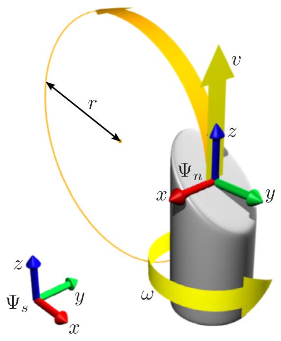
Model setup for the bevel-tip needle with inputs ω and ν.
Bevel-tip flexible needles are asymmetric needles that move along curved trajectories when a forward pushing force is applied. Mechanical properties of these needles have been studied experimentally [1] and their advantages over rigid needles have been shown [2]. The use of a bevel-tip flexible needle as opposed to a symmetric flexible needle [3] has the advantage that needle trajectories can still be influenced even after relatively deep penetration. From a robotics point of view, a bevel-tip needle can be described as a kinematic system with nonholonomic constraints [4], and although motion planning algorithms for such systems exist [5], many of them cannot be applied since the needle only curves when moving forward, not when moving backward. An additional complication is tissue flexibility [6], [7], which is often disregarded for planning purposes, as we do here.
Path planning for bevel-tip needles has been studied in several ways, most of which are applicable only to a planar situation, in which the needle can either curve upward or downward. Alterovitz et al. [8], [9], [10] discretize the full configuration space (translations and rotation) of the needle, and search the resulting discrete state space for optimal paths in the presence of obstacles and uncertainty. Although control laws exist that stabilize the needle motion to a plane [11], truly 3D paths would allow more possibilities than planar paths. Park et al. [12] use a diffusion-based approach to path planning in an obstacle-free 3D environment, but, to the best of our knowledge, no previous work exists that considers path planning for bevel-tip needles in 3D environments with obstacles.
In this paper, we propose a solution to the 3D path planning problem that relies on analytic rather than discretized solutions whenever possible. The specific kinematic properties of the needle allow this, as outlined in Section II, and only the final stages of the path planning formulation require model discretization. By delaying discretization for as long as possible, the resulting quantities remain compact, low-dimensional expressions that are fast to compute and suitable for use in optimization routines. Simulations of the path planning algorithm can be run in a matter of seconds.
The outline of the paper is as follows. Section II presents the model setup of the needle and the details of the path planning problem we are trying to solve. Section III then proposes two specific path planning algorithms, each of which uses a different discretization of the control inputs. Section IV shows simulation results of the two path planners in synthetic environments with and without obstacles, and Section V presents conclusions and possible directions for future research.
II. Model Setup and Control Objective
A. Needle geometry and kinematics
We make the following reasonable assumptions and approximations in order to obtain a finite-dimensional tractable system model. First, we assume that the needle is flexible relative to the tissue, such that the tissue is not displaced during the needle motion. Second, the motion of the needle is fully determined by the motion of the needle tip, i.e. the needle body perfectly follows the needle tip. Third, the needle tip is beveled in such a way that, when pushed forward from the needle base, the needle follows a perfect arc of fixed radius r independent of velocity and tissue properties. Finally, we assume that we can control the orientation of the needle tip by changing the orientation at the base, either because the torsional effect is negligible or because we can compensate for it using realtime tip measurements or accurate torsion models. Experimental results [1] show that needle materials can be chosen such that the needle indeed moves along an arc of approximately fixed radius, although the effects of tissue inhomogeneity and especially needle torsion can be significant and will require compensation.
Under the previous assumptions, the motion of the needle is determined kinematically by two control inputs: the linear forward velocity, denoted ν, and the bevel orientation velocity, denoted ω. We do not consider reverse motion of the needle and hence assume ν ≥ 0 throughout the paper.
Figure 1 shows the model setup. We rigidly attach a coordinate frame Ψn to the tip of the needle, with axes aligned as in the figure, such that the z-axis is the direction of forward motion ν and needle orientation ω, and the beveled tip causes the needle to rotate instantaneously around an axis parallel to the x-axis and passing through the point (0, -r, 0).
Following standard robotics literature [13], the position and orientation of the needle tip with respect to a reference frame Ψs can be described compactly by a 4 × 4 matrix gsn(t) ∈ SE(3) of the form
| (1) |
with Rsn ∈ SO(3) the rotation matrix describing the relative orientation, and psn ∈ T (3) the vector describing the relative position of frames Ψs and Ψn.
The instantaneous linear and angular velocities of the needle are described by a twist Vsn ∈ se(3). For this particular system, the twist is most conveniently expressed in frame Ψn (body coordinates), in which it takes the form
| (2) |
when written as a 6 × 1 vector, or equivalently
| (3) |
when written as a 4 × 4 matrix. The twist relates to gsn as
| (4) |
This kinematic model is the same as the unicycle model in [4]. When the twist is constant, (4) becomes a linear ODE that can be integrated as
| (5) |
for which a relatively simple analytic expression exists [13]. Another way to interpret the needle motion for constant ν and ω is to look at the screw parameters pitch and axis [13], which in this case equal
| (6) |
| (7) |
For constant ν and ω, the needle moves along a helical path with axis l and pitch h.
B. Path planning objective
The goal of the path planning algorithm is to find control actions ω(t), ν(t) such that, starting from Ψs, the needle reaches a goal position Ψg via a reasonably short path, while avoiding any obstacles present in its course (Figure 2). We constrain the needle to start at a specific location (the origin of Ψs) with initial direction of motion along the z-axis of Ψs, leaving the initial bevel orientation angle as an extra degree of freedom. The presented method can be directly extended to include other degrees of freedom in the initial conditions, e.g. the position of the entry point.
Fig. 2.
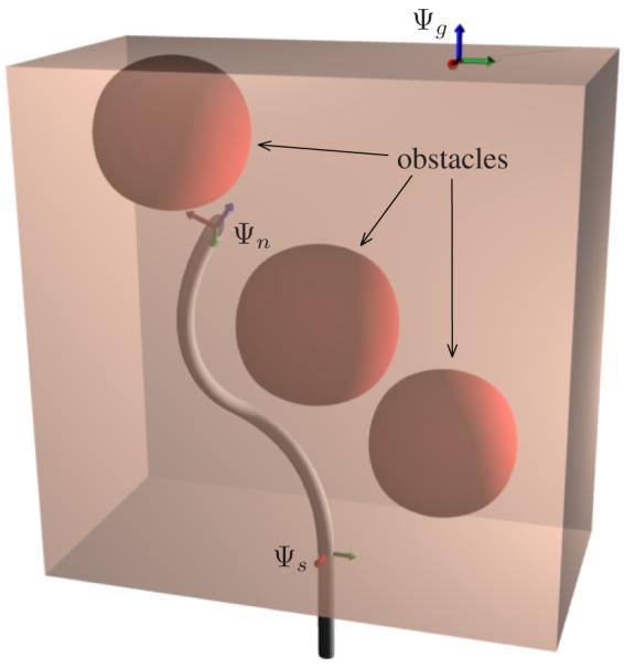
Overview of the control problem: steer the needle (frame Ψn) from Ψs to Ψg with minimal control action while avoiding obstacles.
We express the path planning objective numerically as the minimization of the following cost function
| (8) |
with T the total path length, di(psn(t)) the penetration depth of obstacle i when the needle is at position psn at time t, and αg,ω,l,o positive constants. This cost function jointly expresses several objectives. In order of appearance, these are: deviation of the final needle tip position from the goal location, required control effort along ω, path length, and cost associated with penetration of obstacles. We choose the obstacle penalty to be proportional to the sum of penetration depths of each obstacle, integrated over time. Extensions and adaptations to this cost function can be made if needed, e.g. to include a penalty for deviation from a desired needle orientation at the goal location or to penalize penetration of sensitive obstacles such as arteries more heavily than less sensitive obstacles such as bone.
From (6–7) and by intuition it is clear that, under the assumptions of Section II-A, the trajectory of the needle only depends on the ratio of ω/ν and not on the values of the two individual variables. Although the motion speed is clearly important in practice, for path planning purposes it presents a redundancy: moving along a certain trajectory twice as fast does not change its shape. The cost function reflects this property; it is invariant to scaling of T (and inversely proportional scaling of ω and ν).
The algorithms proposed in Section III are directly based on (8), but both the control variables and the obstacle penalties are approximated through discretization in order to make the problem solvable.
III. Discretized Motion Planning Strategies
The cost function (8) that expresses the path planning goal contains several time integrals that are hard to compute for general motions. A first step towards simplification is to use the observation that needle trajectories (and their cost) only depend on the ratio ω/ν. We therefore set ν(t) ≡ 1 for planning purposes. This is equivalent to parameterizing the trajectory by insertion distance instead of time [11]. One side-effect is that we have to allow for impulsive ω(t) (when changing direction while ν = 0), but this does not pose limitations, as shown in Section III-A.
As a second simplification step, we approximate the integral of the obstacle penetration depths di by a finite sum at discrete times tj ∈ {0,△, 2△, …, T } for suitable △ > 0, and approximate the cost function J in (8) as
| (9) |
where we used the fact that ν(t) ≡ 1. This approximation only penalizes obstacle penetrations at finite times tj, but if △ is chosen sufficiently small, such an approximation should be accurate enough. In addition, we can guarantee obstacle detection for given △ by ’padding‘ the obstacles with a conservative buffer zone of size △.
Using this new approximate cost function, we now present two methods to discretize the function ω(·) such that it can be represented by finitely many parameters. We show how for both methods, the cost function can be expressed analytically.
A. Stop-and-turn strategy
A first discretization strategy (called stop-and-turn) is a generalization of switching control for planar needle steering [8]. Instead of continually varying the orientation of the needle, we first orient the needle (ω ≠ 0, ν = 0), then push it forward (ω = 0, ν ≠ 0), re-orient the needle (ω ≠ 0, ν = 0), etcetera. Although we previously set ν(t) ≡ 1, we can represent a stop-and-turn motion by the impulse train shown in Figure 3(a) and given mathematically as
| (10) |
with tk ≥ 0 the time intervals and δ(t) Dirac‘s delta function.
Fig. 3.
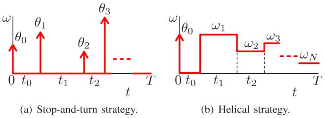
Discretization of ω(t) for two planning strategies.
Given this choice for the structure of ω(·), the total path length becomes T = ∑k tk, and we can calculate the integral term in (9) explicitly as
| (11) |
In addition, we can compute the final position and orientation of the needle analytically as
| (12) |
with
| (13) |
| (14) |
The position error then follows directly as
| (15) |
and hence all terms in the cost function (9) can be expressed analytically, ready to be used for fast numerical optimization.
B. Helical strategy
As a second discretization strategy, we start again from the approximate cost function (9), but we discretize ω(·) to be a piecewise constant function, as illustrated in Figure 3(b), with an impulse θ0 at t = 0 to represent the initial bevel orientation. We also include the extra time segment t0 to obtain an expression that parallels the stop-and-turn strategy.
With this choice of ω(·), the motion of the needle becomes piecewise helical, with pitch and axis given by (6–7) for each piece. The total path length equals T = ∑k tk and the integral term in (9) can be computed analytically as
| (16) |
The final configuration gsn(T) of the needle becomes
| (17) |
where gω(θ) and gv (t) are defined in (13)–(14) and gV(ω, t) denotes the rigid motion along the needle twist for time t at rotation rate ω (and forward speed 1), i.e.
| (18) |
for which an analytic expression can be found in the literature [13]. Again, also for this discretization choice, all terms in the cost function (9) are available analytically.
IV. Simulation Results
We now show simulation results of the two discretization strategies from Section III, applied to several synthetic motion planning problems. Optimizations were performed using a C implementation [14] of the Levenberg-Marquardt algorithm for nonlinear least squares estimation. For all simulations, we chose parameters αg = 1, αω = 10-4 αl = 10-4, αo = 103, and △ = 0.1. These choices are based on quick initial simulation trials and provide an intuitively desired balance between position error, control effort, path length, and obstacle avoidance. Simulation results are not very sensitive to changes in any of the parameters α; trajectory shapes and algorithm convergence remain more or less the same when the parameters are changed by an order of magnitude. Practical values of α will depend on the ’medical cost‘ (e.g. tissue damage) of long paths and sharp turns.
Since the numerical optimization routine may get trapped in local minima of the cost function, we start every optimization problem from several random initial estimates and choose the best one as the optimal solution. Future work will investigate more rigorous methods, e.g. based on inverse kinematics or using different homotopy classes [15].
A. 3D Motion planning without obstacles
We first consider the trajectories in an obstacle-free environment. Figure 4 shows the optimal trajectories for the two strategies for N = 1, i.e. with only four degrees of freedom in the optimization: initial angle θ0 and time segment t0, and remaining angle θ1 (for the stop-and-turn strategy) or angular velocity ω1 (for the helical strategy) and time segment t1. We set the goal position at various locations in a grid with corners (0, -3, 10) and (2, 3, 10).
Fig. 4.
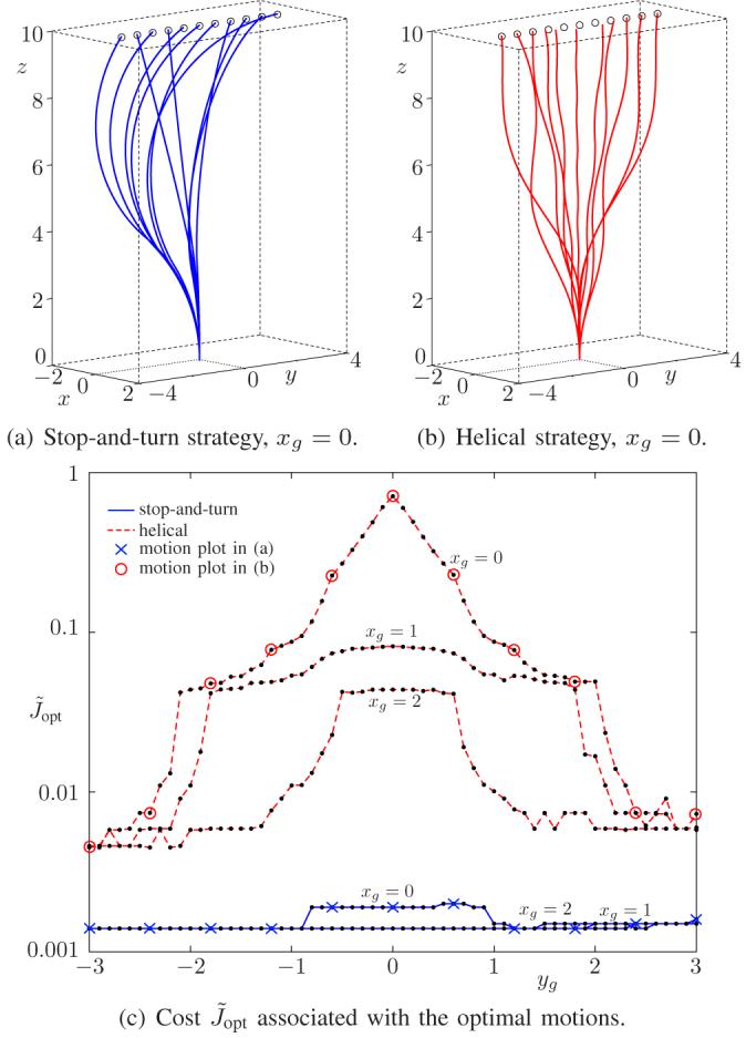
Simulation results in an obstacle-free environment for various goal positions psg = (xg, yg, 10) and minimal . control freedom N = 1.
The figure shows that, for this particular setup, the stop-and-turn strategy has consistent cost around 0.002 and that all goal positions are feasible. The helical strategy has more variable cost, depending on the goal position, and for goal positions near (0, 0, 10) (corresponding to near-vertical displacement), the helical strategy fails to reach the goal. Both graphs contain jagged behavior caused by the optimization routine getting trapped in a local minimum when starting from unfortunately chosen initial estimates. Starting from more initial estimates improves the result.
The graph of the cost function is almost symmetric around yg = 0. This is to be expected, since the obstacle-free path planning problem is the same for positive and negative yg. The slight asymmetry is due to the (small) cost associated with the initial orientation angle θ0, which is larger for goal positions with yg > 0.
The cost function for the helical strategy peaks near psg = (0, 0, 10), which can be explained by looking at the screw motion parameters (6–7). In order to achieve a purely vertical displacement along the z-axis with a single helix, the rotational velocity ω would have to be chosen as ω → ∞ (a high-speed drilling motion). This is clearly prohibited by the cost function, and hence the algorithm converges to a compromise between low position error and low ω, which nevertheless results in a relatively high cost and a deviation of the motion from the desired goal position. The precise compromise depends on the choice of parameters αω and αg. For goal points away from (xg, yg) = (0, 0), the variables θ0, ω1, t0 and t1 are sufficient to achieve good results. Alternatively, if we increase the control freedom to N ≥ 2, the difficulty with near-vertical displacements disappears.
B. 3D Motion planning with obstacles
We now turn to optimal path planning in the presence of obstacles. We consider the problem of reaching the same goal points in the grid cornered by (0, -3, 10) and (2, 3, 10), starting from the origin, while avoiding three spherical obstacles located at (0, 0, 5), (1, 3, 7), (-2, 0, 10), all with radius 2. We set the dimension of the control space to N = 4 and optimize the needle motion for both the stop-and-turn and the helical strategy. We choose N = 4 to demonstrate the kinematic possibilities of the needle, even with few degrees of freedom. The optimal cost is strictly non-increasing with N, since we can always cut one time segment in half (increasing N by 1) and choose the new θk = 0 (for the stop-and-turn strategy) or ωk= ωk-1 (for the helical strategy), without changing the value of the cost function (9).
The results are shown in Figure 5: (a) through (d) show the optimal paths for the two discretization strategies with various goal positions, and (e) shows the optimal cost associated with both strategies and all goal points. The algorithm finds feasible motion paths in the presence of obstacles for most goal positions, but not all. Due to the choice of parameters for the cost function (9) with αo ≫ αg, if the goal position cannot be reached without penetrating an obstacle, the algorithm returns a trajectory that does not reach the goal but avoids the obstacles. This can be seen in the figure: for trajectories with relatively high cost, the goal is not reached but all obstacles are avoided.
Fig. 5.
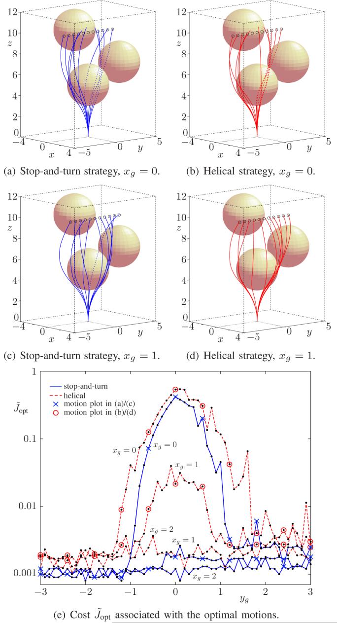
Optimal trajectories in an environment with three obstacles for various goal positions and N = 4 control actions.
Contrary to the obstacle-free example with N = 1, the computed curves of the two strategies for this example look more alike and their corresponding costs are more similar. This is to be expected, since both discretizations approximate the same signal ω(t), and both approximations should converge to the same continuous signal as N increases. Although the stop-and-turn strategy consistently outperforms the helical strategy in terms of the cost function, we cannot conclude that the stop-and-turn strategy is indeed always better. To decide on this question, a more quantitative and medically motivated cost function should be used: one that determines the cost based on the amount of tissue damage, accuracy of motion prediction, simplicity of implementation, possibilities for real-time adjustments to account for deviations, and requirements for (medical image) feedback. At this point, we can say qualitatively that both strategies produce promising trajectories.
Just as in the obstacle-free example, the graph of the cost function contains jagged sections, corresponding to relatively low and high cost trajectories. More extended simulations show that some of the high-cost trajectories correspond to local minima that can be avoided by starting from a different initial estimate, but other high-cost trajectories still remain. It is not obvious how to distinguish between high-cost solutions due to the numerical algorithm, high-cost solutions due to lack of control freedom (requiring larger N), and high-cost solutions due to obstacles prohibiting paths of reasonable length altogether. An example of the last category are the goal positions near (0, 0, 10), which are ’blocked‘ by the obstacle at (0, 0, 5).
V. Conclusions and Future Work
This paper discusses a new path planning algorithm for bevel-tip flexible needles in a rigid 3D environment with obstacles. It shows how the kinematics of the needle can be integrated analytically if a suitable discretization is chosen for the rotational velocity of the needle, i.e. its control input. Two discretizations are presented: a stop-and-turn strategy, in which the needle is alternately rotated around its axis and pushed forward without rotation, and a helical strategy, in which the needle is pushed forward at constant speed and at the same time rotated at a piecewise constant angular speed.
Given the discretization of the control input, the path planning problem can be cast as a nonlinear optimization problem, which can be solved quite efficiently due to the analytic expression for the position of the needle as a function of the control input. Simulations of the optimization for a synthetic 3D environment show the feasibility of the proposed approach, as well as its speed (less than a second for a typical setup) compared to previous algorithms.
Several important issues are still open for future research. Two immediate questions that arise are (1) will the algorithm always find a solution if one exists, and (2) if a solution is found, is it the global optimum. The algorithm attempts to solve a nonlinear non-convex optimization problem, and hence global convergence is not guaranteed. In the simulations, the algorithm was run from several initial estimates and the best result was chosen from these runs, but such a search is clearly never exhaustive. Future research should investigate more systematic ways to choose initial estimates. We also plan to incorporate the presented path planning algorithm as part of a global approach to path planning, e.g. based on probabilistic roadmaps [16].
A second aspect that needs to be further addressed is the required frequency and accuracy of position measurements during needle insertion. These practical requirements influence the choice of discretization for the control input. More switching instants in the path (more control freedom) will generally imply more uncertainty and hence require more measurements to be taken to verify the behavior of the needle.
Another important issue is modeling uncertainty. Alterovitz et al. [8] presented a method explicitly incorporating uncertainty in 2D motion planning, and it would be very useful to extend this idea to the 3D case. Other modeling aspects that could be added as extensions to the presented approach include more general obstacles, deformable tissue, and a periodically changing environment due to respiration or cardiac motion.
Acknowledgments
This work is supported in part by the National Institutes of Health under grant R01 EB006435 and by the Netherlands Organization for Scientific Research (NWO). We also thank Vinutha Kallem, Noah Cowan, and Allison Okamura from Johns Hopkins University for their helpful comments.
References
- [1].Webster RJ, III, Memisevic J, Okamura AM. Design considerations for robotic needle steering. Proceedings of the IEEE International Conference on Robotics and Automation; April 2005. [Google Scholar]
- [2].Engh JA, Podnar G, Khoo SY, Riviere CN. Flexible needle steering system for percutaneous access to deep zones of the brain. Proceedings of the IEEE 32nd Annual Northeast Bioengineering Conference; April 2006.pp. 103–104. [Google Scholar]
- [3].DiMaio S, Salcudean SE. Needle steering and motion planning in soft tissues. IEEE Transactions on Biomedical Engineering. 2005 June;52(6):965–974. doi: 10.1109/TBME.2005.846734. [DOI] [PubMed] [Google Scholar]
- [4].Webster RJ, III, Kim JS, Cowan NJ, Chirikjian GS, Okamura AM. Nonholonomic modeling of needle steering. International Journal of Robotics Research. 2006;5/6(May):509–525. [Google Scholar]
- [5].Kolmanovsky I, McClamroch NH. Developments in nonholonomic control problems. IEEE Control Systems Magazine. 1995 December;15(6):20–36. [Google Scholar]
- [6].Goksel O, Salcudean SE, Dimaio SP. 3D simulation of needle-tissue interaction with application to prostate brachytherapy. Computer Aided Surgery. 2006 November;11(6):279–288. doi: 10.3109/10929080601089997. [DOI] [PubMed] [Google Scholar]
- [7].Glozman D, Shoham M. Image-guided robotic flexible needle steering. IEEE Transactions on Robotics. 2007 June;23(3):459–467. [Google Scholar]
- [8].Alterovitz R, Lim A, Goldberg K, Chirikjian GS, Okamura AM. Steering flexible needles under Markov motion uncertainty. Proceedings of the IEEE/RSJ International Conference on Intelligent Robots and Systems (IROS); August 2005.pp. 120–125. [Google Scholar]
- [9].Alterovitz R, Goldberg K, Okamura A. Planning for steerable bevel-tip needle insertion through 2D soft tissue with obstacles. Proceedings of the IEEE International Conference on Robotics and Automation; April 2005.pp. 1640–1645. [Google Scholar]
- [10].Alterovitz R, Branicky M, Goldberg K. Constant-curvature motion planning under uncertainty with applications in image-guided medical needle steering. Proceedings of Workshop on the Algorithmic Foundations of Robotics; July 2006. [Google Scholar]
- [11].Kallem V, Cowan NJ. Image-guided control of flexible bevel-tip needles. Proceedings of the IEEE International Conference on Robotics and Automation; April 2007; pp. 3015–3020. [DOI] [PMC free article] [PubMed] [Google Scholar]
- [12].Park W, Kim JS, Zhou Y, Cowan NJ, Okamura AM, Chirikjian GS. Diffusion-based motion planning for a nonholonomic flexible needle model. Proceedings of the IEEE International Conference on Robotics and Automation; April 2005.pp. 4611–4616. [Google Scholar]
- [13].Murray RM, Li Z, Sastry SS. A Mathematical Introduction to Robotic Manipulation. CRC Press; 1994. [Google Scholar]
- [14].Lourakis MIA.Levmar: Levenberg-Marquardt nonlinear least squares algorithms in C/C++ 2004Julyhttp://www.ics.forth.gr/~lourakis/levmar/, accessed on August 13, 2007
- [15].Jaillet L, Siméon T. Path deformation roadmaps. Proceedings of the International Workshop on the Algorithmic Foundations of Robotics; July 2006. [Google Scholar]
- [16].Kavraki LE, Švestka P, Latombe J-C, Overmars MH. Probabilistic roadmaps for path planning in high-dimensional configuration spaces. IEEE Transactions on Robotics and Automation. 1996 August;12(4):566–580. [Google Scholar]


