

Abstract
The first microelectromechanical-system normally closed electrothermal valve constructed using Parylene C is described, which enables both low power (in milliwatts) and rapid operation (in milliseconds). This low-power valve is well suited for applications in wirelessly controlled implantable drug-delivery systems. The simple design was analyzed using both theory and modeling and then characterized in benchtop experiments. Operation in air (constant current) and water (current ramping) was demonstrated. Valve-opening powers of 22 mW in air and 33 mW in water were obtained. Following integration of the valve with catheters, our valve was applied in a wirelessly operated microbolus infusion pump, and the in vivo functionality for the appropriateness of use of this pump for future brain mapping applications in small animals was demonstrated.
Index Terms: Drug delivery, electrothermal valve, Parylene C, wireless operation
I. Introduction
In the past decade, the use of Parylene [poly(p-xylylene)] as a structural material in microelectromechanical systems (MEMS) devices has attracted significant attention, particularly for implantable drug-delivery systems that integrate sensing, pumping, and valving [1]-[3]. Parylene C, known for its biocompatibility, is widely used in implantable medical devices. Parylene C is also compatible with MEMS microfabrication processes. Advanced drug-delivery systems can benefit from the excellent mechanical and electrical properties of Parylene C.
Electrothermal valves are critical flow-regulating elements in many microfabricated drug-delivery devices (Table I) [4]-[10]. Valve operation is analogous to that of electrical fuses, and the primary component is a resistive metallic element (typically platinum or gold). The electrothermal valve is normally closed and single use. The valve-membrane blocks the flow path until it is activated, at which point it is thermally removed. In earlier work, metal, silicon, or silicon nitride composites were investigated as electrothermal membrane materials [4]-[6]. When electrical power was applied, the resistive element melted the thin-film membrane of the valve to open the flow path. However, significant power was required to generate the melting temperature for these materials. By substituting with a low-melting-temperature polymer, power consumption is significantly decreased to improve valve performance. A few electrothermal valves employing polymer membranes, such as uncross-linked SU-8, polyethylene/polyethylene terephthalate, polydimethylsiloxane, and polymethylmethacrylate, were reported [7]-[10]. These polymer valves tend to take longer to open compared to nonpolymer valves [4]-[6]. By decreasing the thickness, the valve activation time for polymer valves can be reduced. For implantable drug-delivery applications, valves must be biocompatible [11]. Only one existing valve had biocompatible construction. However, due to the metallic membrane construction (Pt or Ti), the valve also had high power consumption (2.25 W) [4].
TABLE I.
Comparison of the Parylene Electrothermal Valve With the Valves Reported in Research Literature
| Maloney [4] | Cardenas-Valencia [5] | Mueller [6] | Hong [7] | Guerin [8] | McDonald [9] | Luo [10] | Our Device | |
|---|---|---|---|---|---|---|---|---|
| Membrane Materials | Pt/Ti/Pt | SiNx | Doped Silicon | Un-crosslinked SU-8 |
PE/PET Film | PDMS | PMMA | Parylene |
| Membrane Dimension L × W × T (μm) |
50×50×0.01 | 3000×3000×3 | N/A×N/A×50 | N/A×N/A×50 | N/A×N/A×35 | 100×60×20 | 500×500×100 | ø500 × 10 (thick) |
| Thermal Element Materials |
Pt/Ti/Pt | Pt/Ti | Doped Si | Ni | Cu | Pt | Au | Pt |
| Thermal Element Thickness (nm) |
1/10/1 | 30/9 | 50000 | 5000 | N/A | N/A | 1000 | 100 |
| Mass Transport Mechanism |
Diffusion | Pressure Driven | Pressure Driven | Pressure Driven | Pressure Driven | Pressure Driven |
Diffusion | Pressure Driven |
| Max. Pressure (kPa (psi)) |
N/A | 500.0 (72.5) | 20684.3 (3000) | 96.5 (14) | 200.0 (29) | N/A | N/A | 689.4 (100) |
| Melting Temperature (°C) |
1770 | 700 | 1400 | 50 | 120 | 675 | 490 | 290 |
| Opening Power (mW) |
2250 | 16000 | 300 | 288 | 400 | 150 | 67 | 22 |
| Applied Voltage (V) |
N/A | 70 | N/A | 0.7 | 1.5 | 420 | 2.8 | 3.6 |
| Applied Current (mA) |
1000 | N/A | N/A | N/A | N/A | N/A | N/A | 7 |
| Opening Time (ms) |
0.01 | 20 | 0.1 | 1000 | 1200 | 1000 | 15000 | 100 |
| Energy (mJ) |
0.025 | 320 | 30 | 288 | 400 | 150 | 1005 | 2.5 |
| Biocompatibility | Yes | No | No | No | No | No | No | Yes |
| Microfabrication Compatibility |
Yes | Yes | Yes | Yes | No | No | Yes | Yes |
| Delivered Material (Solid/Liquid/Gas) |
Solid/Liquid | Liquid | Gas | Gas | Liquid | Liquid | Liquid | Liquid |
Here, Parylene C (a biocompatible polymer [2], [3], [12]) is selected as the heater-supporting membrane material. Parylene can be thermally oxidized, degraded (between 125 °C and 200 °C) [13], or melted (290 °C) [14] at lower temperatures than previously used polymers and enables a low-power valve that is suitable for wireless implants. Our electrothermal valve membrane consists of a thin-film Pt element sandwiched in Parylene (with thickness < 10 μm to improve both power consumption and valve-opening speed). The valve is placed in the fluid flow path of a catheter and is opened by thermal degradation or melting following the application of electrical current (Fig. 1). The theory, finite-element modeling (FEM), design, fabrication, and testing of our valve are presented. The application of our Parylene electrothermal valve in a wireless powered micro infusion pump [1], [15]-[17] is also discussed. This implantable pump stores radioactive solution for on-demand injection into animals for neuroimaging of cerebral blood flow. A biocompatible and low-power valve allowing rapid and wirelessly activated release of the radioactive drug is required for this application. Thus, our valve enables, for the first time, a new functional neuroimaging paradigm for understanding behavior in freely moving untethered mice.
Fig. 1.
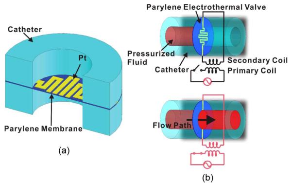
Parylene electrothermal valve. (a) Schematic diagram (cross-sectional view) illustrating the components of the valve. (b) Illustration of the operation principle of the valve in which wireless power transfer is used.
II. Design
The electrothermal drug-delivery valve consists of an electron-beam-evaporated thin-film Pt resistive element embedded in a flexible Parylene membrane (10 μm) (Fig. 2). The center portion of the Pt resistive element corresponds to the active area of the valve. Parylene C (Specialty Coating Systems, Inc., Indianapolis, IN) was selected as the membrane material for its mechanical strength (Young’s modulus of 2.76 GPa [14]), biocompatibility, and ease of integration. It is recognized by the United States Pharmacopeia as a Class VI material that is suitable for the construction of implants, and furthermore, it is well established as a MEMS material [12]. Parylene further simplifies the valve design by obviating the need for an etched silicon membrane support.
Fig. 2.

(a) Illustrations of the electrothermal valve layout in both top and cross-sectional views. (b) Photograph of a single valve. (c) Close-up of a valve element. Both (b) and (c) are reprints of Fig. 1(a) and (b) in [16], reprinted with the permission of the Chemical and Biological Microsystems Society.
Three different serpentine geometries for the resistive elements were selected, each having a different occupied circular area and element linewidth (Table II). The serpentine shape maximizes the total resistance of the element within the designated valve footprint. Two contact pads extending from the electrothermal element provide a convenient location for external electrical connections.
TABLE II.
Valve-Design Parameters
| Valve ID | A | B | C |
|---|---|---|---|
| Layout |

|
||
| Occupied Diameter (μm) |
330 | 500 | 500 |
| Element Line Width (μm) |
20 | 20 | 40 |
| Total Element Length (μm) |
1780 | 3880 | 2380 |
The valve is situated in the fluid flow path, which, in the implementation described here, is the lumen of a catheter. Fig. 1 shows a wireless implementation of the electrothermal valve, in which the valve is triggered when the connected secondary coil is activated by an external primary coil. The power transmitted to the secondary coil allows current to pass through the resistive element and initiates Joule heating to thermally degrade or melt the Parylene membrane surrounding the element. When the electrical (Pt element) and mechanical connections (Parylene membrane) of the valve are broken, the valve opens and allows pressurized fluids to pass. The catheter implementation facilitates incorporation of the valve with commercially available tubing having circular cross sections. This simple single-use low-power valve is easily modified to accommodate other geometries commonly encountered in microfabricated microfluidic systems.
III. Theory and Modeling
A. Mechanical Modeling
The Parylene electrothermal valve prevents flow from a pressurized source prior to activation. To ensure that the Pt element can survive the typical peak pressure from a fluid reservoir [1 atm (101.3 kPa)], the mechanical robustness of the membrane was verified using both large-deflection approximation and nonlinear FEM. First, a simplified nonlinear isotropic homogeneous circular clamped thin film (Parylene only) was modeled under uniformed applied pressure. Due to the complex composite structure of the electrothermal valve membrane (Parylene/Pt), this idealized analytical model may deviate from the actual mechanical response. Thus, a more realistic valve model using a nonlinear FEM model was also examined.
1) Large-Deflection Theory
In large-deflection theory [18], [19], the nonlinear strain-displacement relations resulting from bending and stretching of a plate can be expressed as
| (1) |
where εx, εy, and γz are the strains and u, v, and w are the displacements in x-, y-, and z-directions, respectively. The corresponding governing differential equations of the plate are
| (2) |
where φ is the stress function, E is Young’s modulus, t is the thickness of the plate, D is the flexural rigidity, and p is the applied pressure. By using the minimum-strain-energy method, the solution for a clamped thin circular plate subject to a uniform load (p0) is
| (3) |
2) Finite-Element Simulation
Nonlinear static simulation of the electrothermal valve was also performed using FEM (COSMOSWorks 2007, SolidWorks Company, Concord, MA) (Fig. 3). The mechanical properties of the materials and applied loads used in this FEM study are listed in Table III. Several critical stress points were identified [Fig. 3(b)]. The results indicated that the maximum stress of the Pt element under 1-atm applied pressure is 1.53 GPa, which is less than the tensile strength of the Pt thin film (4.8 GPa). Thus, the electrical connections are expected to survive pressurized conditions that arise during radiotracer loading.
Fig. 3.

Finite-element analysis using COSMOSWorks. (a) Nonlinear and transient FEM model and its corresponding coordinate system. (b) Stress distribution (1 atm).
TABLE III.
Material Mechanical Properties and Parameters Used in FEM
| Material Properties or Parameters | Values |
|---|---|
| Density of Parylene (kg·m−3) | 1289 [14] |
| Density of Parylene (kg·m−3) | 21450 [25] |
| Young’s Modulus of Parylene (GN·m−2) | 2.76[14] |
| Young’s Modulus of Platinum (GN·m−2) | 172 [25] |
| Tensile Strength of Parylene (MN·m−2) | 68.9[14] |
| Tensile Strength of Platinum (GN·m−2) | 4.80 [26] |
| Poisson’s Ratio of Parylene | 0.40 [14] |
| Poisson’s Ratio of Platinum | 0.39 [25] |
| Applied Pressure (kN·m−2) | 0.0405 |
| Thickness of Parylene Membrane, LParylene (μm) | 10.0 |
| Thickness of Platinum, LPt (μm) | 0.2 |
B. Temperature of the Pt Element
The temperature of the thin-film Pt element can be predicted by a conventional calibration method commonly used in thermal anemometry [2]. This method includes determination of the temperature coefficient of resistivity (TCR) and overheat temperature (OHT) for the thin-film metal resistor. TCR is an important parameter to predict Pt element resistance at different temperatures. The temperature dependence of Pt is approximately linear over the range of interest and can be expressed as
| (4) |
where R(T) is the resistance at temperature T, T0 is an appropriate reference temperature, and α is the TCR. In addition, the OHT allows the temperature of the resistive element to be calculated from its resistance. Pt element resistances for different applied currents were obtained. Then, the temperature of the valve Pt element was estimated by using the following equation and the experimentally determined TCR:
| (5) |
C. Thermal Modeling
The valve-opening process is dependent on the heat transfer from the resistive heating element to the valve-membrane material. Therefore, thermal modeling was performed to evaluate heat transfer in the electrothermal valve system. First, a 1-D steady-state heat-transfer analysis was used to model the temperature of the valve under constant applied electrical power. Due to the nonuniform geometry of the valve, this idealized analytical model is limited but provides some information regarding the valve-opening mechanism. A transient finite-element simulation was also performed using a more realistic valve model.
1) Analytical Modeling
A 1-D steady-state heat-transfer analysis uses a uniform simplified thermal resistance model to discuss the temperature of the valve (Fig. 4). Only the top half of the valve model is used in the analysis due to symmetry. Assuming steady-state conditions, the heat-transfer rate is expressed as
| (6) |
where q is the heat generated by the Pt thermal element, T2 is the Parylene temperature at the Parylene–air boundary, T∞ is the ambient temperature, RParallel denotes the combined parallel thermal resistances of the glass and air, Rair is the thermal resistance of the air, Rglass is the thermal resistance of the glass tubing, hair is the convective heat-transfer coefficient of the air, kglass is the thermal conductivity of the glass tubing, Aair is the contact area of the air and Parylene membrane, Aglass is the contact area of the glass catheter and Parylene membrane, and Lglass is the thickness of the glass catheter. Therefore, the boundary temperature of the Parylene and air can be expressed as
| (7) |
Similarly, if the membrane is in contact with water instead of air, hair and Aair can simply be substituted with hwater and Awater. The thermal properties used in the calculations are listed in Table IV. The calculated temperatures for 9 mA of applied current (corresponding to 40.5 mW) at the air–Parylene and water–Parylene boundaries are 474.0 °C and 126.6 °C, respectively. In the case of air operation, the boundary temperature exceeds the Parylene melting temperature (290 °C), and valve opening is expected. However, to open the valve in water, T2 must exceed 290 °C corresponding to a minimum applied power of 105.6 mW. For a 500-Ω Pt thermal element, the corresponding minimum opening current is 14.5 mA.
Fig. 4.

(a) Schematic showing a 1-D heat-transfer model of the Parylene electrothermal valve. (b) and (c) Final model representing only the top half of the valve due to symmetry.
TABLE IV.
Material Thermal Properties and Parameters Used in Analytical and FEM
| Material Properties or Parameters | Values |
|---|---|
| Thermal Conductivity of Parylene, kparylene (W·m−1·K−1) | 0.084 [14] |
| Thermal Conductivity of Glass Tubing, kglass (W·m−1·K−1) | 0.937 [27] |
| Thermal Conductivity of Platinum (W·m−1·K−1) | 73.0 [25] |
| Convection Heat Transfer Coefficient of Air and Parylene boundary, hair (W·m−2·K−1) |
5[28] |
| Convection Heat Transfer Coefficient of Water and Parylene boundary, hwater (W·m−2·K−1) |
200[28] |
| Specific Heat of Parylene (J·kg−1·K−1) | 0.712 [14] |
| Specific Heat of Platinum (J·kg−1·K−1) | 131.2 [25] |
| Applied Electrical Power, q (W) | 0.0405 |
| Ambient Temperature, T∞ (°C) | 25.0 |
| Thickness of Glass Tubing, Lglass (mm) | 10.0 |
This simplified 1-D thermal resistance model can only predict the temperature of a uniform, homogeneous, and layered structure. However, multiple heat propagation routes exist, and the Pt thermal element possesses complex geometry. Using FEM, the valve-opening mechanism can be examined in more detail.
2) Finite-Element Simulation
The steady-state and transient temperature profiles of the electrothermal valve were modeled using FEM (COSMOSWorks 2007, SolidWorks Company, Concord, MA). The same model [Fig. 3(a)] used in mechanical FEM modeling was again applied in valve thermal FEM analysis. The heat-diffusion equation governs the thermal behavior of the system and is expressed as
| (8) |
where k is the thermal conductivity, T is the temperature, q is the energy generated inside the system, ρ is the density, and cp is the specific heat. A cylindrical coordinate system is used with two basic assumptions: 1) k is constant, and 2) axisymmetric geometry exists. Therefore, the governing equation becomes
| (9) |
where I is the applied current, R is the resistance of the Pt element, and V is the volume of the Pt element. The boundary conditions at the interface between the Parylene and top and bottom air interfaces are
| (10) |
| (11) |
where LParylene is the thickness of the Parylene membrane. Similarly, if the membrane is in contact with water instead of air, hair can simply be substituted with hwater.
At the center of the Pt element, due to the axial symmetry of the temperature distribution along the r−z plane, the boundary condition is
| (12) |
At the edge of the Parylene membrane, the boundary condition is (assuming adiabatic conditions and no heat dissipation)
| (13) |
where a is the radius of the Parylene membrane.
The initial condition at t = 0 is
| (14) |
The governing equation (9), the boundary conditions (10)-(13), and the initial condition (14) are then used in the steady-state and transient FEM models to solve for the temperature distributions of the valve at different time increments.
The thermal properties listed in Table IV were used in both steady-state and time-dependent thermal simulations. First, steady-state FEM was performed with air as the fluid medium. The maximum temperature of the valve calculated by steady-state FEM was 499.6 °C and in close agreement with the 1-D analytical value of 474.0 °C. Transient FEM temperature profiles are shown in Fig. 5. A 40.5-mW power was applied to the Pt thermal resistive element. Convective cooling was applied on the Parylene membrane and air boundary. By 133 ms, the majority of the valve area reached over 125 °C, which is the thermal oxidation initiation temperature of Parylene C. The Parylene melting temperature of 290 °C was reached in the central region at 266 ms. By 400 ms, most of the valve area exceeded the Parylene melting temperature, at which point a near-complete opening of the valve is expected. By 2.66 s (2660 ms), the maximum temperature of the valve reached 499.4 °C, which was close to the steady-state FEM result (499.6 °C). Complete valve opening is defined as complete thermal removal of the valve membrane in the flow path. In the simulations, the temperature at the center of the valve was higher than at the edge due to the geometrical arrangement of the Pt element. Therefore, it is expected that thermal degradation will start from the center and expand toward the edges.
Fig. 5.

Finite-element analysis using COSMOSWorks: The results of transient thermal FEM modeling showing the temperature distribution of the valve at three time steps. This figure is a reprint of Fig. 2(d) in [16], reprinted with the permission of the Chemical and Biological Microsystems Society.
IV. Fabrication
A. Valve-Membrane Fabrication
The valves were constructed using standard microfabrication techniques, beginning with a 3-in silicon wafer. The native oxide on the silicon surface was preserved to facilitate Parylene-membrane release at the end of the process. First, a 5-μm-thick Parylene-C layer was deposited [Fig. 6(a)] to form the first layer of the Parylene/metal/Parylene sandwich. A dual-layer photoresist process was used to form a sidewall profile with an undercut to facilitate metal liftoff. First, AZ1518 photoresist (AZ Electronic Materials, Branchburg, NJ) was spin coated at 4000 r/min for 30 s (1.5 μm), followed by global UV exposure (90 mW/s). Then, AZ4400 photoresist (AZ Electronic Materials, Branchburg, NJ) was applied at 4000 r/min for 30 s (4.2 μm). The dual-layer photoresist was selectively exposed (90 mW/s) [Fig. 6(b)]. Following development in AZ351 developer (AZ Electronic Materials, Branchburg, NJ) for ~45 s, an undercut sidewall profile was obtained. Following a short descum in oxygen plasma, a 100-nm Pt film was e-beam evaporated, and the resistive element and contact pad were revealed by liftoff of the photoresist in acetone, isopropyl alcohol, and then deionized (DI) water [Fig. 6(c)].
Fig. 6.

Fabrication process flow for the Parylene MEMS electrothermal valve. (a) Deposition of the bottom 5-μm-thick Parylene. (b) Liftoff lithography and Pt e-beam evaporation. (c) Pt liftoff. (d) Deposition of the top 5-μm-thick Parylene. (e) Contact-pad lithography and reactive ion etching. (f) Removal of photoresist, Parylene-film release, and hand dice of the device. This figure is a reprint of Fig. 5 in [1], reprinted with the permission of the Transducer Research Foundation.
Prior to depositing the second layer of Parylene C (5 μm), a brief oxygen plasma clean (60 W, 100 mT, 30 s) was performed. The final Parylene layer (5 μm thick) was deposited [Fig. 6(d)]. Contact pad openings were defined by lithography (8 μm of AZ4400 at 1500 r/min for 30 s), and Parylene was etched in oxygen plasma (100 W, 100 mT, 1 min) to expose the metal [Fig. 6(e)]. Finally, the photoresist mask was stripped, the entire wafer was immersed into DI water to release the thin-film valves from the substrate, and the individual devices were cut out manually [Fig. 6(f)]. The Parylene deposited on silicon substrates with native oxide may be peeled off; this release is facilitated by immersion in water [20].
B. Valve Packaging
A packaged valve situated in the lumen of a catheter with the contact-pad flaps folded back along the catheter to connect to the control circuitry is shown in Fig. 7. First, the valve was sandwiched between two short glass tubes (Accu-Fill 90, Becton, Dickinson and Company, Franklin Lakes, NJ) and two laser-machined (Mini/Helix 8000, Epilog, Golden, CO) double-sided adhesive rings (Tape 415, 3M, St. Paul, MN). These adhesive rings temporarily connect and align the valve to the top and bottom catheter segments. Then, conductive epoxy (Ohmex-AG, Transene Company, Inc., Danvers, MA) was applied to join electrical wires to the contact pads (cured at 150 °C for 15 h). This assembly was strengthened with a bead of epoxy (5 Minute Epoxy System, ITW Performance Polymers, Riviera Beach, FL). In this strengthening step, the double-sided rings applied in the earlier step prevented leakage of epoxy into the flow path. This assembly process was performed under a stereo microscope.
Fig. 7.

Illustrated assembly process for the Parylene electrothermal valve. (a) Exploded view of components. (b) Conductive epoxy joins wires to the valve. (c) Epoxy bonding of the assembly. Photographs of (d) components for (left) the valve package and (right) the completely packaged valve in a catheter. Images (a)–(c) are reprints of Fig. 6(a)–(c) in [1], reprinted with the permission of the Transducer Research Foundation.
V. Experimental Methods
Both mechanical and thermal performances of the Parylene electrothermal valve were characterized. Mechanical characterization was performed in a benchtop experiment and then compared with the results of large-deflection and nonlinear FEM analyses. Next, the Pt resistive element temperature and the electrical valve-opening parameters in both air and water were obtained. The results for air operation were compared to that of transient FEM analysis.
A. Mechanical Strength of the Valve Membrane
A custom testing apparatus was laser machined in acrylic. The valve was clamped in this test fixture with a circular clamping area matching the inner diameter of the catheters. The input port of this fixture was connected to a regulated pressure testing apparatus that supplies a uniform pressure load. The applied pressure was from 2.5 to 15 lbf/in2 (17.2–103.4 kPa), with a pressure increment of 2.5 lbf/in2 (17.2 kPa). The deflections of the valve under applied pressures were measured using a compound microscope (Motic PSM-1000, Motic, Xiamen, China) with vertical focusing control of 1 μm [Fig. 8(a)].
Fig. 8.

Schematic diagrams of the experimental apparatus for (a) load-deflection testing and (b) electromechanical testing that allow for visual observation of the electrothermal valve.
B. Temperature of the Pt Element
The temperature of the thin-film Pt element was determined using the TCR and OHT calibrations. First, the resistance values of the Pt element were recorded with data-acquisition hardware (LabVIEW 7.1 with 2400 SourceMeter, Keithley Instruments, Inc., Cleveland, OH) while being subjected to known temperatures in an oven (EC0A Environmental Chamber, Sun Electronic Systems, Inc., Titusville, FL) calibrated with a platinum resistance temperature detector (RTD-2-F3105-36-T, Omega, Stamford, CT) to obtain the TCR. Subsequently, the relationship between the applied current and resistance was acquired. These data were used to determine the temperature rise of the Pt element using (5).
C. Valve Opening in Air
The valve-opening experiments were performed in both air and water. The valve was clamped in a test fixture and connected to a constant-current power supply (2400 SourceMeter, Keithley Instruments, Inc., Cleveland, OH). The opening process was monitored through a compound microscope and recorded using a computer-controlled charge-coupled device camera (PL-A662, PixeLINK, Ottawa, Canada) [Fig. 8(b)].
In air, the valve-opening power and current were obtained by applying constant current starting from 1 mA and increasing in small increments; the current at which each valve opened was recorded. The corresponding opening power values were also calculated. The devices were evaluated by using the testing setup [Fig. 8(b)] but with air in the cavity directly below the valve. The thermal events resulting in valve opening were captured using time-sequence microscopy.
D. Valve Opening in Water
For opening the valve in water, current ramping was used. Five ramping rates were evaluated to determine the optimal condition for reliable and repeatable valve opening. The experimental apparatus [Fig. 8(b)] allowed rapid electrical connections and facilitated visual observation of the valve. Current biasing and resistance measurement were performed simultaneously using the Keithley SourceMeter. Water was introduced below the valve but not on the top so that the valve condition was easily assessed with a compound microscope.
VI. Results and Discussion
A. Mechanical Strength of the Valve Membrane
The experimentally obtained load-deflection curve for the composite Parylene/Pt/Parylene valve membrane is shown in Fig. 9. Also plotted are the nonlinear analytical and FEM results; both exhibit good agreement with empirical results. The maximum deflections at the center of the valve were calculated to be 44.5 μm for large-deflection theory and 49.7 μm for the nonlinear FEM under 15 lbf/in2 (103.4 kPa). In the range of the applied pressures tested (0–15 lbf/in2, 0–103.4 kPa), the composite membrane had a maximum deflection of 49.2 μm and did not undergo plastic deformation, and no obvious resistance change was measured after pressure application.
Fig. 9.

Comparison of the experimental data with the nonlinear FEM model and large-deflection approximation. This figure is a reprint in Fig. 4[1] reprinted with the permission of the Transducer Research Foundation.
B. Temperature of the Pt Element
A representative TCR calibration is shown in Fig. 10, and a typical TCR value for our e-beam-deposited thin-film Pt was 1.40 × 10⁻³/K (or 0.14%/K). As expected, the TCR value of the thin-film Pt is lower than that of the bulk material (3.92 × 10⁻³/K) [2]. This TCR value and (5) were used to predict the Pt element temperature for different applied currents in the OHT calibration (Fig. 11). To prevent destructive thermal degradation of the device under test, the OHT experiments were performed at currents that were far below those resulting in valve opening (maximum applied current of 2.5 mA), and the results were extrapolated to higher current ranges by using a second-order polynomial curve fit. For a device with an initial resistance of 617 Ω, the valve-opening current that was higher than 4.6 mA was expected, given that the Parylene-C melting temperature is 290 °C Note that this current setting corresponds to the temperature of the Pt element in air. However, complete valve opening requires elevation of the Parylene-membrane temperature in addition to that of the adjacent Pt trace above the Parylene melting temperature. Thus, opening currents that result in complete valve opening whereby the flow path was completely unobstructed was expected to occur at currents that were greater than 4.6 mA.
Fig. 10.

Representative TCR calibration curve for an electrothermal valve. The slope of the curve corresponds to the empirically obtained TCR (α).
Fig. 11.

Representative OHT calibration curve showing (open square) the resistance and (open circle) OHT as a function of the applied current.
C. Valve Opening in Air
Valves were successfully opened in air under constant applied current (Fig. 12). Fig. 12(a) shows the breach in the Parylene membrane left by an opened valve (15 mA), and Fig. 12(b) shows a magnified view of the edge of melted valve opening. Different valves having resistances ranging from 617 to 125 Ω (for the three different resistive element designs, each having only a small resistance deviation between identical devices) were successfully opened in air under constant applied currents ranging from 7 to 20 mA, respectively [Fig. 12(c)]. The corresponding valve-opening powers are from 22 to 50 mW. Fig. 12(c) also shows that the valve-opening current and power decreased with increasing valve element resistance. The opening currents here are the minimum values that are necessary to achieve valve opening. The typical opening time at the minimum opening current is a few seconds and can be reduced by applying higher current. However, faster opening is achieved at a cost of higher power consumption. In addition, the increased thermal stress may result in breakage of the thin Pt trace prior to complete valve opening.
Fig. 12.

Results for valve opening in air. (a) Open valve (15 mA). (b) Magnified view of the edge of the valve orifice. (c) Valve-opening-current- and power-to-resistance relationship. This figure is a reprint of Fig. 8 in [1], reprinted with the permission of the Transducer Research Foundation.
Valve opening is the result of a sequence of thermal events (Fig. 13). At 133 ms, a thermally oxidized Parylene region in the valve area was visually apparent. At 266 ms, the Parylene membrane began melting, resulting in small openings between the windings of the serpentine Pt trace. By 400 ms, large gaps in the valve membrane have formed, and valve opening is nearly complete. These experimental data corroborate the transient FEM results (Fig. 5). More specifically, the simulations enable prediction of valve-opening time, visualization of the heat-transfer paths, and determination of the temperature distribution across the valve over time. Note that, in this valve design, complete valve opening requires that the majority of the valve area must exceed the Parylene melting temperature. To further reduce power consumption and opening time, the geometric layout of the Pt trace can be modified to minimize the Parylene area to be melted (i.e., by constraining the metal trace to the circumference of the valve) for more efficient heat transfer to the Parylene membrane. This modified design is expected to consume less power and open faster and will be investigated in future work.
Fig. 13.
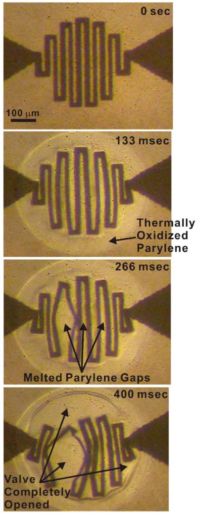
Experimentally obtained time-sequence microscope images for valve-opening testing depicting the corresponding thermal events.
D. Valve Opening in Water
Valve opening in water was evaluated using current ramping instead of constant current biasing. In the case of constant current biasing, significant heat dissipation into water was encountered in this mode, which prohibited reliable and repeatable valve opening. When higher currents were applied to compensate for the increased heat loss to the fluid, premature failure of the Pt element was observed before complete valve opening. The current overshoot provided by the power supply was less than 1%, so trace failure may be attributed to other causes such as thermal stress induced by the difference of the coefficients of thermal expansion between Pt and Parylene (e.g., Pt of 9.1 × 10⁻⁶/°C versus Parylene of 3.5 × 10⁻⁵/°C) or electromigration (the atoms in the Pt trace are removed due to the impact with high-energy electrons) [5], [10]. Therefore, current ramping was applied to optimize the heat transfer to the Parylene membrane for operation in water/liquid.
During current ramping, the valve area was observed through a microscope in real time while simultaneously tracking the resistance. Valve operation for five ramping rates (0.025–2 mA/s) was assessed in order to obtain the optimal biasing conditions for repeatable and reliable valve opening. The current-ramping profiles are shown in Fig. 14, and the inset provides a detail of the current-ramping profile for 0.1 mA/s. Current was increased in incremental steps of 0.2 mA every 2 s. All three valve designs were characterized.
Fig. 14.
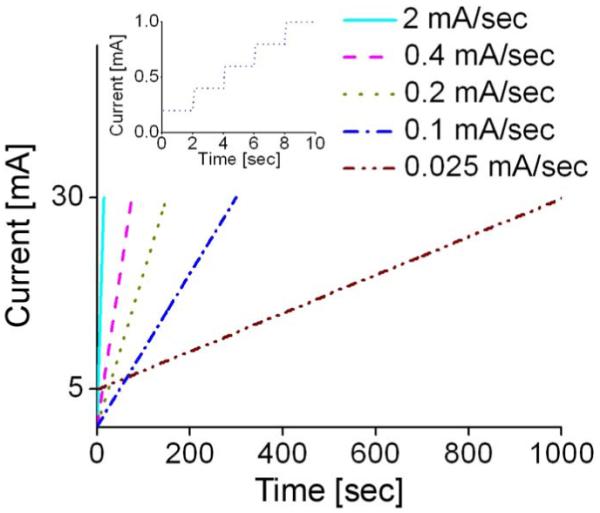
Current-ramping profile. The inset shows a close-up of the 0.1-mA/s waveform. For 0.025 mA/s, the opening time was shorted by initiating the applied current from 5 mA. This figure is a reprint of Fig. 10 in [1], reprinted with the permission of the Transducer Research Foundation.
The results for the current-ramping experiments are summarized in Table V. Successful valve opening is defined as the case of complete valve opening in which the valve membrane is completely removed and no longer obstructs the flow path. Therefore, partial or otherwise incomplete opening is considered unsuccessful valve opening. Ramping rates that were lower than 0.1 mA/s resulted in the most consistent opening performance, and all three valve designs were successfully opened under these conditions. For rates of 0.2 mA/s and above, opening was inconsistent. The observed failure mode was breaking of the Pt lines prior to complete opening.
TABLE V.
Optimization Results for Current-Ramping Testing in Water
| Ramping Rate (mA/sec) |
Valve ID | ||
|---|---|---|---|
| A | B | C | |
| 0.025 | Open | Open | Open |
| 0.1 | Open | Open | Open |
| 0.2 | Not Open | Not Open | Open |
| 0.4 | Open | Not Open | Not Open |
| 2.0 | Not Open | Not Open | Not Open |
Representative examples of the valve-opening process for each of the three valve designs are shown in Fig. 15. The resistance during valve opening was monitored, and the corresponding resistance change to observable opening events was recorded. These events include the onset of membrane melting, breaking of the metal element, and opening of the valve. In one example shown (valve design C), the Pt element line did not break during valve opening due to the increased linewidth (40 μm compared to 20 μm for the other two designs). Note that current ramping involves nonuniform dynamic heat transfer and, as a result, was not modeled, given the limitations of the FEM software package. However, experimental results do suggest that current ramping preserves traces, allowing sufficient time for heat transfer to occur and fully open valves in the presence of water.
Fig. 15.

Representative results for valve opening in water. (Left column) Real-time resistance monitoring of the valve. (Right column) Time-lapse images of valve opening corresponding to resistance-measurement events in the left column plots. (a)–(c) Valve-opening testing results corresponding to three valve designs A, B, and C, respectively. Fig. 15(a) is a reprint of Fig. 9 in [1], reprinted with the permission of the Transducer Research Foundation.
The valve-opening currents were higher for water than for operation in air. This is expected, given the higher rate of heat transfer into water than air and thus necessitates a higher opening current due to the unwanted heat loss. When practical, an air bubble may be introduced between the water and valve to reduce the opening current and increase the opening speed. For example, opening times of 150 s were typical for 0.1 mA/s in water compared to a few seconds in air. This approach, however, may not be practical for all applications. As previously mentioned, the layout of the Pt trace may be optimized to reduce power consumption and limit thermal loss to the surrounding fluid. Thus, valve-layout improvements will be pursued to avoid the long opening times and complex circuitry associated with the use of current ramping. Preliminary experiments with valves having traces limited to the periphery of the valve-membrane area suggest that the desired performance improvements are possible by following this line of investigation.
Our Parylene- and Pt-based electrothermal valve possesses many advantages compared to the previous electrothermal valves listed in Table I. First, the Parylene/Pt membrane is biocompatible and thus suitable for implantation. Parylene can be melted at lower temperature compared to metal or silicon; therefore, our valve has lower power consumption, which is desirable in implantable devices. The selection of Parylene as a valve-membrane material also has other implications. Parylene’s mechanical strength allows mechanically robust thin films that can withstand pressure gradients without plastic deformation. Compared to nonpolymer valves, our Parylene valves were fabricated using simple processes and can easily be integrated with a variety of microfluidic systems. The fastest valves are nonpolymer valves; however, in some cases, Parylene can offer better power consumption. Having a thinner Parylene valve membrane compared to other polymer valves improves both power consumption (~60 times) and opening time (~10 times). Meanwhile, a thin Parylene membrane was microfabricated (10 μm) and offered better power consumption and opening time to other polymer valves. This thin Parylene valve can withstand higher pressure compared to other polymer valves due to its much higher mechanical strength.
VII. In Vivo Application
Previously, a microbolus infusion pump (MIP) for rapid and wireless drug delivery in freely moving untethered rats was described for the specific purpose of functional neuroimaging of behavior [21]-[23]. This imaging paradigm involves the rapid intravenous delivery of a radiotracer, followed by lethal injection, brain removal, slicing, and autoradiographic processing of labeled tissue slices to obtain a statistical parametric mapping. This 3-D reconstruction of the brain details changes in brain activation patterns captured by labeling cerebral blood flow [24].
A critical enabler in this imaging paradigm is the rapid delivery of radiotracer and euthanasia agent to preserve the time resolution of behavioral events and to prevent nonspecific diffusion associated with slow infusion methods. A miniature solenoid valve provided rapid opening to allow delivery from a pressurized reservoir. However, the size and bulk of the solenoid valve prohibits its use in a MIP that is suitable for transgenic mice (32-g pump compared to a typical 40-g mouse). To our knowledge, there are no commercial valves that meet the requirements for a mouse-compatible MIP. Our Parylene electrothermal valve meets all requirements for this application, including low weight, low power, and rapid opening.
The Parylene electrothermal valve was integrated into an implantable MIP that is suitable for use in mice [Fig. 16(a)] [1]. The pump consists of a reservoir, valve, catheter, secondary coil, and tuning capacitors. The total weight of the system is less than 10% of the animal weight (4 g). In benchtop experiments, wireless activation of the valve was successfully demonstrated using the mouse emitter coil cage (primary coil) [Fig. 16(b)].
Fig. 16.

Neuroimaging application of Parylene electrothermal valve. (a) MIP. (b) In vivo testing setup. (c) Photograph comparing the MIP and a mouse. Fig. 16(a) and (c) are reprints of Fig. 11(a) and (b) in [1], reprinted with the permission of the Transducer Research Foundation.
In vivo valve triggering was also demonstrated. First, the mouse was cannulated, and the pump reservoir was loaded with pentobarbital (50 mg/kg)/potassium chloride (3 mol/L). The pump was implanted subcutaneously in the dorsum of the mouse and sutured. To observe the valve triggering, the catheter was left outside the mouse. After energizing the primary coil around the mouse cage, euthanasia solution flowed out of the catheter due to successful triggering of the electrothermal valve. Fig. 16(c) compares the dimensions of the MIP and a mouse. Detailed experiments in mice using this new MIP enabled by our MEMS valve are under way.
VIII. Conclusion
We have successfully developed a disposable low-power Parylene-C MEMS electrothermal valve that is suitable for drug-delivery applications. The design, modeling, fabrication, in vitro benchtop characterization, and preliminary in vivo testing have been described. The TCR and OHT experiments have allowed prediction of the temperature of the Pt element and determination of the appropriate current to apply to open the valve. Opening powers of 22–50 mW have been obtained in air, and reliable valve opening in water using a current-ramping rate of 0.1 mA/s has been achieved. Further reduction in power consumption and optimization of valve performance are planned. Also, additional experiments will evaluate the performance of the valve in the presence of the radiotracer agent and in vivo functional neuroimaging experiments.
Acknowledgment
The authors would like to thank Dr. D. Zhu, Dr. T. Hoang, N. Sardesai, and the members of the Biomedical Microsystems Laboratory, Department of Biomedical Engineering, University of Southern California, for their contributions to this paper.
This work was supported in part by the National Institute of Neurologic Disorders and Stroke under Grant 1 R01 NS050171.
Biography

Po-Ying (Brian) Li (M’07) received the B.S. degree in mechanical engineering from Tatung Institute of Technology, Taipei, Taiwan, in 1996, the M.S. degree in mechanical engineering from National Tsing Hua University, Hsinchu, Taiwan, in 2001, and the M.S. degree in materials science from the University of Southern California, Los Angeles, in 2004. He received the Ph.D. degree in electrical engineering in 2009.
He was a Research Assistant in the Composite Structure Laboratory, National Tsing Hua University, from 1999 to 2001. He is currently a Member of the Biomedical Microsystems Laboratory, Department of Biomedical Engineering, University of Southern California. His research is focused on the characterization of the mechanical properties of carbon-fiber-reinforced composite-laminate materials.
Mr. Li is a member of the American Society of Mechanical Engineers, the American Chemical Society, and the American Vacuum Society.

Tina K. Givrad received the B.S. degree in electrical engineering from Islamic Azad University, Tehran, Iran, in 1992, the M.S. degree in electrical engineering from California State University, Los Angeles (CSULA), in 1996, and the Ph.D. degree in biomedical engineering from the University of Southern California, Los Angeles, in 2007.
Following her graduation from CSULA, she began working for the Boeing North American Defense Group. She is currently a Postdoctoral Research Associate with the Department of Biomedical Engineering, USC. Her research focus has been on the design and fabrication of microbolus pumps for rapid drug infusion used for functional neuroimaging applications in small animals.
Dr. Givrad is a member of the American Society of Mechanical Engineers, the Biomedical Engineering Society, and the Society for Neuroscience.

Daniel P. Holschneider received the B.A. degree in chemistry from The Johns Hopkins University, Baltimore, MD, in 1984, the M.D. degree from the University of North Carolina at Chapel Hill in 1988, and training in clinical psychiatry at the University of California, Los Angeles, in 1993.
He is currently an Associate Professor in the Departments of Psychiatry and Behavioral Sciences, Neurology, Cell and Neurobiology, and Biomedical Engineering, University of Southern California, Los Angeles. His research focus has been on animal models, functional brain mapping in freely moving animals, physiologic monitoring, and technology development (implantable infusion pumps and cardiac output monitoring).

Jean-Michel I. Maarek received the engineering degree (Diplome d’Ingénieur Civil des Mines) in chemical engineering from the Ecole des Mines, Nancy, France, in 1980, the Doctorat Ingénieur degree in biomedical engineering from the Université Paris Val-de-Marne, Créteil, France, in 1984, and the M.S. degree in education from the University of Southern California, Los Angeles, in 1997.
He is currently an Associate Professor of engineering practice with the Department of Biomedical Engineering, University of Southern California, where he is also a Principal Investigator with the Alfred E. Mann Institute for Biomedical Engineering for the Cardiac Output Monitor Project. His research interests are in physiologic monitoring of cardiovascular function, medical device development, and biomedical signal analysis.

Ellis Meng (M’02–SM’09) received the B.S. degree in engineering and applied science and the M.S. and Ph.D. degrees in electrical engineering from the California Institute of Technology (Caltech), Pasadena, in 1997, 1998, and 2003, respectively.
She joined the Department of Biomedical Engineering, University of Southern California, Los Angeles, in 2004, as an Assistant Professor, where she currently holds a joint appointment in the Ming Hsieh Department of Electrical Engineering. She holds the Viterbi Early Career Chair in the Viterbi School of Engineering. She is also currently the Thrust Leader for Interface Technology, the Associate Director of Education, and a Student Diversity Researcher at the National Science Foundation Biomimetic MicroElectronic Systems Engineering Research Center. Her research interests include bio-MEMS, implantable biomedical microdevices, microfluidics, multimodality integrated microsystems, and packaging.
Dr. Meng was a recipient of the Intel Women in Science and Engineering Scholarship, the Caltech Alumni Association Donald S. Clark Award, the NSF CAREER Award, the Wallace H. Coulter Foundation Early Career Translational Research Award, and the Caltech Special Institute Fellowship. She was recently recognized as a Technology Review (TR) 35 Young Innovator Under 35. She is a member of Tau Beta Pi, the Biomedical Engineering Society, the Society of Women Engineers, and the American Society for Engineering Education.
Footnotes
Color versions of one or more of the figures in this paper are available online at http://ieeexplore.ieee.org.
Contributor Information
Po-Ying Li, Department of Electrical Engineering, University of Southern California, Los Angeles, CA 90089 USA (poyingli@usc.edu).
Tina K. Givrad, Department of Biomedical Engineering, University of Southern California, Los Angeles, CA 90089 USA (givrad@usc.edu).
Daniel P. Holschneider, Departments of Psychiatry and Behavioral Sciences, Neurology, Cell and Neurobiology, and Biomedical Engineering, University of Southern California, Los Angeles, CA 90033 USA (holschne@usc.edu)
Jean-Michel I. Maarek, Department of Biomedical Engineering, University of Southern California, Los Angeles, CA 90089 USA (jmaarek@bmsr.usc.edu)
Ellis Meng, Departments of Biomedical and Electrical Engineering, University of Southern California, Los Angeles, CA 90089 USA (ellis.meng@usc.edu).
References
- [1].Li P-Y, Givrad TK, Holschneider DP, Maarek J-MI, Meng E. A wirelessly-activated Parylene electrothermal valve for mapping brain function in freely moving subjects; presented at the Solid-State Sensors, Actuators, Microsystems Workshop; Hilton Head Island, SC. 2008. [Google Scholar]
- [2].Meng E, Li P-Y, Tai Y-C. A biocompatible Parylene thermal flow sensing array. Sens. Actuators A, Phys. 2008 May;144(1):18–28. [Google Scholar]
- [3].Li P-Y, Shih J, Lo R, Saati S, Agrawal R, Humayun MS, Tai Y-C, Meng E. An electrochemical intraocular drug delivery device. Sens. Actuators A, Phys. 2008 May;143(1):41–48. [Google Scholar]
- [4].Maloney JM, Uhland SA, Polito BF, Sheppard NF, Jr., Pelta CM, Santini JT., Jr. Electrothermally activated microchips for implantable drug delivery and biosensing. J. Control. Release. 2005 Dec.109(1–3):244–255. doi: 10.1016/j.jconrel.2005.09.035. [DOI] [PubMed] [Google Scholar]
- [5].Cardenas-Valencia AM, Dlutowski J, Bumgarner J, Munoz C, Wang W, Popuri R, Langebrake L. Development of various designs of low-power MEMS valves for fluidic applications. Sens. Actuators A, Phys. 2007 May;136(1):374–384. [Google Scholar]
- [6].Mueller J, Yang E-H, Green A, White V, Chakraborty I, Reinicke R. Design and fabrication of MEMS-based micropropulsion devices at JPL; Proc. SPIE; San Francisco, CA. 2001.pp. 57–71. [Google Scholar]
- [7].Hong C-C, Choi J-W, Ahn CH. Disposable air-bursting detonators as an alternative on-chip power source; Proc. 15th IEEE Int. Conf. Micro Electro Mech. Syst.; Las Vegas, NV. 2002.pp. 240–243. [Google Scholar]
- [8].Guerin LJ, Dubochet O, Zeberli JF, Clot PACP, Renaud PARP. Miniature one-shot valve; Proc. 11th IEEE Int. Conf. Micro Electro Mech. Syst.; Heidelberg, Germany. 1998.pp. 425–428. [Google Scholar]
- [9].McDonald JC, Metallo SJ, Whitesides GM. Fabrication of a configurable, single-use microfluidic device. Anal. Chem. 2001 Dec.73(23):5645–5650. doi: 10.1021/ac010631r. [DOI] [PubMed] [Google Scholar]
- [10].Luo C, Liu X, Poddar R, Garra J, Gadre AP, Keuren EV, Schneider T, White R, Currie J, Paranjape M. Thermal ablation of PMMA for water release using a microheater. J. Micromech. Microeng. 2006 Mar.16(3):580–588. [Google Scholar]
- [11].Jain KK. Drug delivery system. In: Walker JM, editor. Methods in Molecular Biology. Vol. 437. Humana Press; Totowa, NJ: 2008. [DOI] [PubMed] [Google Scholar]
- [12].Meng E, Li P-Y, Tai Y-C. Plasma removal of Parylene C. J. Micromech. Microeng. 2008 Apr.18(4):045004. [Google Scholar]
- [13].Grattan DW, Bilz M. The thermal aging of Parylene and the effect of antioxidant. Stud. Conserv. 1991;36:44–52. [Google Scholar]
- [14].SCS Parylene Properties2008. [Online]. Available: http://www.scscoatings.com/docs/coatspec.pdf.
- [15].Li P-Y, Holschneider DP, Maarek J-MI, Meng E. Parylene electrothermal MEMS drug delivery valve; Proc. Spring Nat. Meeting ACS; New Orleans, LA. 2008.pp. 941–942. [Google Scholar]
- [16].Li P-Y, Givrad TK, Holschneider DP, Maarek J-MI, Meng E. Mechanical and thermal modeling of a Parylene electrothermal valve for mapping brain function in freely moving subjects; Proc. 12th Int. Conf. Miniaturized Syst. Chem. Life Sci.; San Diego, CA. 2008.pp. 1105–1107. [Google Scholar]
- [17].Li P-Y, Holschneider DP, Maarek J-MI, Meng E. Parylene electrothermal valve for rapid in vivo drug delivery; presented at the American Vacuum Society (AVS) 55th Int. Symp. Exhibition; Boston, MA. 2008. [Google Scholar]
- [18].von Karman T. Encyklopadie der Mathematischen Wissenschaften. Vol. 4. Teubner; Leipzig, Germany: 1910. Festigkeitsprobleme in Machinenbau; pp. 348–352. [Google Scholar]
- [19].Ugural AC. Stress in Plate and Shells. 2nd ed. McGraw-Hill; New York: 1999. [Google Scholar]
- [20].Rodger DC, Fong AJ, Li W, Ameri H, Ahuja AK, Gutierrez C, Lavrov I, Zhong H, Menon PR, Meng E, Burdick JW, Roy RR, Edgerton VR, Weiland JD, Humayun MS, Tai Y-C. Flexible Parylene-based multielectrode array technology for high-density neural stimulation and recording. Sens. Actuators B, Chem. 2008 Jun.132(2):449–460. [Google Scholar]
- [21].Holschneider DP, Maarek J-MI, Harimoto J, Yang J, Scremin OU. An implantable bolus infusion pump for use in freely moving, nontethered rats. Amer. J. Physiol. Heart Circ. Physiol. 2002 Oct.283(4):H1 713–H1 719. doi: 10.1152/ajpheart.00362.2002. [DOI] [PMC free article] [PubMed] [Google Scholar]
- [22].Holschneider DP, Yang J, Sadler TR, Nguyen PT, Givrad TK, Maarek J-MI. Mapping cerebral blood flow changes during auditory-cued conditioned fear in the nontethered, nonrestrained rat. NeuroImage. 2006 Feb.29(4):1344–1358. doi: 10.1016/j.neuroimage.2005.08.038. [DOI] [PMC free article] [PubMed] [Google Scholar]
- [23].Moore WH, Holschneider DP, Givrad TK, Maarek J-MI. Transcutaneous RF-powered implantable minipump driven by a class-E transmitter. IEEE Trans. Biomed. Eng. 2006 Aug.53(8):1705–1708. doi: 10.1109/TBME.2006.873698. [DOI] [PMC free article] [PubMed] [Google Scholar]
- [24].Holschneider DP, Maarek J-MI. Brain maps on the go: Functional imaging during motor challenge in animals. Methods. 2008 Aug.45(4):255–261. doi: 10.1016/j.ymeth.2008.04.006. [DOI] [PMC free article] [PubMed] [Google Scholar]
- [25].Physical properties of the platinum metals. Platin. Met. Rev. 1972 Apr.16(2):59. [Google Scholar]
- [26].Wang K, Yao K, Chua SJ. Titanium diffusion and residual stress of platinum thin films on Ti/SiO2/Si substrate. J. Appl. Phys. 2005 Jul.98(1):013538. [Google Scholar]
- [27].de Mello AJ, Habgood M, Lancaster NL, Welton T, Wootton RCR. Precise temperature control in microfluidic devices using Joule heating of ionic liquids. Lab Chip. 2004 Oct.4(5):417–419. doi: 10.1039/b405760k. [DOI] [PubMed] [Google Scholar]
- [28].Liu Z, Chan H, Li WJ, Dong Z, Wang Y. Finite element modeling of a thermally actuated polymer micro robotic gripper; Proc. Int. Conf. Inf. Acquis.; 2004.pp. 88–91. [Google Scholar]