Abstract
We report the design, construction, and testing of a contact lens with an integrated amperometric glucose sensor, proposing the possibility of in situ human health monitoring simply by wearing a contact lens. The glucose sensor was constructed by creating microstructures on a polymer substrate, which was subsequently shaped into a contact lens. Titania sol-gel film was applied to immobilize glucose oxidase, and Nafion® was used to decrease several potential interferences (ascorbic acid, lactate, and urea) present in the tear film. The sensor exhibits a fast response (20 sec), a high sensitivity (240 µAcm−2mM−1) and a good reproducibility after testing a number of sensors. It shows good linearity for the typical range of glucose concentrations in the tear film (0.1–0.6 mM), and acceptable accuracy in the presence of interfering agents. The sensor can attain a minimum detection of less than 0.01 mM glucose.
Keywords: Contact lens, Glucose sensing, Tear film, Polymer microfabrication, Non-invasive continuous health monitoring
1. Introduction
Glucose sensors have been the subject of intense research for decades. Although several functioning and practical sensors exist, including the one developed by Clark and Lyons more than 40 years ago (Clark and Lyons, 1962), the drive still continues. Many of the recent efforts have targeted the field of personalized medicine, attempting to develop small and reliable sensors that would allow continuous glucose monitoring in diabetic patients. An especially inviting avenue is non-invasive (or minimally invasive) sensing, and several innovative technologies have been developed in pursuit of this goal (Ferrante do Amaral and Wolf, 2008). Non-invasive detection is usually achieved by placing the sensing element on the skin, and engineering a detector that can sense tissue glucose without piercing the skin. Some examples are iontophoretic extraction of glucose through the skin (Tierney et al., 1999), visible (Yeh et al., 2003) or near-IR (Maruo et al., 2003) absorption spectrometry, and polarimetry (Cameron and Coté, 1997).
An alternative route to decrease the invasive nature of glucose monitoring would be to take the measurements from urine, saliva or tear fluid. A major disadvantage of this approach is its intermittent nature: all of these fluids need to be collected before a measurement can be made, so that truly continuous sensing has not been a possibility. Recently, however, several sensor designs have emerged that could allow continuous monitoring in the tear fluid.
A glucose-sensitive contact lens has been prepared by immobilizing two types of fluorescent indicators in the lens material as it is polymerized (March et al., 2004). In the absence of glucose, the indicators are bound to one another, and the fluorescence emission is quenched. In the presence of glucose, they dissociate and fluorescence is detected. The signal is read with the aid of an illumination/recording unit held in front of the eye. The operation of such a sensor has been demonstrated in a clinical setting. Another similar system is based on embedding photonic crystals in a hydrogel patch, creating a holographic hydrogel (Alexeev et al., 2004). When the hydrogel is illuminated, the wavelength of the refracted light varies with the glucose concentration. It has been proposed that such a hydrogel material could be incorporated in a contact lens and the wearer could read out the glucose level by matching the color of the patch to a graduated scale.
An alternative method involves preparing an electrochemical sensor on a flat plastic support, either by microfabrication methods (Iguchi et al., 2007) or by screen printing techniques (Kagie et al., 2008). Since such sensors are flexible, they can either be attached onto the eye directly (Iguchi et al., 2007) or rolled up and inserted into the tear canal (Kagie et al., 2008). The approach shows promise since both devices were demonstrated to have sufficient sensitivity for glucose detection in tear fluid. However, neither report included documented validation of accuracy with respect to interfering electroactive species present in tear fluid (mainly ascorbic acid), so it has been somewhat unclear what the practical viability of such sensors is.
When it comes to the validity of using tear glucose measurements as an indicator of blood glucose levels, differing views exist. Some studies conclude that tear and blood glucose levels are poorly correlated (LeBlanc et al., 2005), whereas other studies have found that there is a correlation (Baca et al., 2007a). When considering reasons for the discrepancy, it has been suggested that the act of tear fluid sampling could introduce a false bias in the results, and thus obscure possible correlation between blood and tear glucose. Indeed, there is evidence that collection methods that irritate the conjunctiva give rise to the highest tear glucose results (Baca et al., 2007b).
Against this background, a contact lens would be the ideal vehicle for continuous tear glucose monitoring: although a novel platform for sensing purposes, a contact lens is a long-proven concept that has been engineered to the point where irritation to the eye is minimal, and insertion/removal is easy. It circumvents any tear fluid sampling issues, since the sensor is brought in contact with tear fluid by completely natural means (normal secretion and blinking). Indeed, studies utilizing a contact lens-bound fluorescent indicator have shown reasonable correlation between the tear and blood glucose profiles (March et al., 2004). Despite the promising scenario of contact lens-borne glucose sensing, practical applications have been slow to materialize. So far, the fluorescent indicator is the only example of a glucose sensor that has actually been placed in (or on) a contact lens.
Sensitivity enhancement and interference rejection are especially important for glucose measurement in the tear fluid. This is because typical tear glucose levels are on the order of 0.1–0.6 mM, which is considerably lower than glucose concentration in serum (4–6 mM) (Berman, 1991). Yet the main interfering species, ascorbic acid and urea, are present at roughly the same levels in tear fluid and serum: ascorbic acid at around 40 µM, urea at around 6 mM (Berman, 1991). As a result, detection requirements for a tear glucose sensor are more stringent than those for a blood glucose sensor.
This paper describes a microfabricated amperometric glucose sensor that has been integrated onto a contact lens. The fabrication process is practical, since all the electrodes are prepared using the same metal structures (Ti/Pd/Pt). The sensor structure is robust, and remains functional even after the heat-molding process to form the contact lens. By immobilizing glucose oxidase in a titania sol-gel layer, sensitivity can be greatly enhanced to satisfy the low level detection requirement for glucose determination in tear fluid. The use of a Nafion® permselective film affords the sensor with good interference rejection characteristics. Such a layered sensor construction has been previously shown to be successful for glucose sensing (Yu et al., 2003)
2. Materials and methods
2.1. Chemicals and solutions
Dibasic sodium phosphate, monobasic sodium phosphate and sodium chloride were purchased from J.T.Baker. D-(+)-glucose, urea, L-ascorbic acid, glucose oxidase (GOD) type VII (from Aspergillus niger) and titanium isopropoxide (97%) were purchased from Sigma-Aldrich. Sodium L-lactate and MES buffer (0.1 M MES pH 6.0–10% PEG 600) were purchased from Fluka. Nafion® solution (5% wt.) was purchased from Clearwater.
To be more consistent with physiological pH conditions, the buffer solution was prepared with 130 mM sodium chloride, 10 mM dibasic sodium phosphate and 10 mM monobasic sodium phosphate in deionized (DI) water, at pH 7.4. The solutions were sonicated for about 20 minutes to equilibrate them with ambient pressure to prevent the formation of micro bubbles during test. Different solutions were prepared with glucose, ascorbic acid, lactate and urea, at least 1 hour before test. GOD solution was prepared in MES buffer with a concentration of 10 mg/mL before use. Other chemicals were just used as received.
2.2. Sensing principles
Enzyme-based electrochemical glucose sensors are widely used due to their high selectivity and high efficiency. There are mainly two kinds of enzymes, GOD and PQQ-glucose dehydrogenases (PQQ-GDH) (Heller and Feldman, 2008). Of these two alternatives, GOD exhibits superior substrate specificity and enhanced operating stability (Li et al., 2009), and hence was applied in our experiment design. The main reactions are as follows (Miyashita et al., 2009).
- Enzymatic glucose recognition:
- Electrochemical oxidation of H2O2 for label-free sensing:
2.3. Sensor design and fabrication
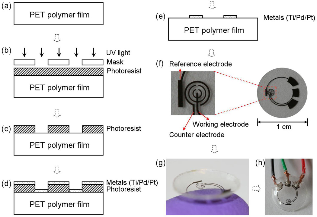
In order to integrate the glucose sensor onto a contact lens, for first trial, the sensor was designed according to a normal lens dimension, and fabricated on a 100 µm thick film of flexible and transparent polyethylene terephthalate (PET) polymer. The fabrication processes and a typical resultant sensor are shown in Fig. 1. Microfabrication on polymer substrates is challenging because of the material’s thermal and mechanical limitations, but can be performed if optimized fabrication processes are used (Stauth and Parviz, 2006; Saeedi et al., 2008).
Fig. 1.
The sensor fabrication process and results: (a) a clean PET substrate is prepared; (b) the substrate is covered by photoresist and exposed to UV light through a mask; (c) the photoresist is developed; (d) thin metal films are evaporated on the sample; (e) after lift-off the metal pattern remains on the surface. After this step, the sensor is cut out of the polymer substrate and heat molded to the contact lens shape and functionalized with enzymes; (f) images of a sensor after it has been cut of the substrate ; (g) image of a completed sensor after molding held on a finger; (h) the sensor may be hardwired for testing.
The PET polymer was purchased from Policrom, and then cut to the standard 4-inch wafer shape using a CO2 laser cutter. Prior to microfabrication, the polymer wafer was cleaned with acetone, isopropyl alcohol (IPA) and DI water in sequence (Fig. 1(a)). After spin-coated with a layer of photoresist AZ4620 (approximately 6 µm thickness), the wafer was soft baked at 65 °C for about 20 min, and then the photoresist was exposed and developed (Fig. 1(b)–(c)). In the following step, three layers of metal (Ti 10 nm, Pd 10 nm and Pt 100 nm) were evaporated in sequence without breaking vacuum (Fig. 1(d)). After lift-off in acetone for about 10 minutes (Fig. 1(e)), the 4-inch plastic wafer was cleaned with IPA and DI water, dried with nitrogen gas, and then cut to small pieces with 1 cm diameter (Fig. 1(f)). Subsequently, the small sensor was heat-molded to the shape of a contact lens (Fig. 1(g)), with electrodes on the outside surface. It should be noted that the addition of Pd between Ti and Pt is important because Pd works as a metal diffusion barrier layer (Cheng et al., 2006), as well as increases signal stability. The latter effect is most likely due to increased stability of a Ti/Pd/Pt reference electrode, as compared to a Ti/Pt electrode.
Fig. 1(f) shows the sensor design. Similar to a standard electrochemical cell, the sensor was composed of three electrodes: the working electrode is where the reaction of interest occurs; the counter electrode acts as the current drain; and the reference electrode provides a stable reference potential. The working and counter electrodes were designed as concentric rings, in order to minimize resistance between them. The bare plastic surface between the working electrode and the counter electrode was used as a platform to immobilize GOD. This simplifies the fabrication process since there is no need to deposit a specific adherent layer for GOD (Fang et al., 2003). The working electrode is a pattern of 50 µm wide rings, and the counter electrode is a 75 µm wide ring with an overall surface area greater than the working electrode. In this arrangement, the working electrode surface is the point of highest impedance, which ensures that the current signal is strictly determined by conditions at the working electrode. The reference electrode was designed as a rectangular bar (1.6 mm × 0.25 mm) near the sensing area. Three large pads (each about 2 mm2) were used to make electrical connections between an external potentiostat and the sensor for testing.
The current system is hardwired for demonstrating the sensor capabilities, as shown in Fig. 1(h). The three pads were connected to electrical wires by silver conductive epoxy (from MG Chemicals) and then isolated with non-conductive epoxy (from ITW Devcon). In future, we envision powering the sensor and reading the results wirelessly. The electrode structures were placed on the edge of the contact lens, leaving the central area clear in order not to occlude the normal visual path for the user.
2.4. Sensor preparation and measurement setup
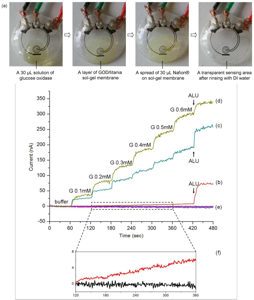
Prior to surface modification, the sensor was rinsed thoroughly with DI water and dried with nitrogen gas. A 30 µL GOD solution (10 mg/mL) was dropped onto the sensor area. Then, the sensor was suspended vertically above a titanium isopropoxide solution in a sealed dish for 6 h to create a GOD/titania sol-gel membrane, just as reported (Yu et al., 2003). After forming the sol-gel membrane, a 30 µL aliquot of Nafion® solution was dropped onto the same area of the sensor, and allowed to dry in air for about 20 min. Prior to measurement, the sensor was rinsed thoroughly with DI water and kept in buffer solution at 4 °C. Images of the surface modification sequence are shown in Fig. 2(a).
Fig. 2.
Images of the sensor as it goes through surface functionalization and the related measured responses. (a) sequential images of sensor pre-treatment with GOD/titania/Nafion®; (b) measured amperometric response for the sensor just incubated with GOD; (c) measured amperometric response for the sensor prepared with GOD/titania sol-gel film; (d) measured amperometric response for the sensor prepared with GOD/titania/Nafion®; (e) three controls (signals for buffer) for the same pretreatment of (b), (c), and (d); (f) the enlarged view of curve (b) and control of (b) for 120–360 sec.
Electrochemical measurements were performed using a BASi Epsilon-EC potentiostat, applying a constant potential of +400 mV between the working electrode and the reference electrode, and recording the current flowing through the working electrode. The counter electrode was connected to the auxiliary lead of the potentiostat, which serves as a current drain. The current was recorded with sample interval of 1 sec. During test, the sensor was suspended in the buffer solution with a volume of 1.8 mL in a small beaker. Different solutions were added manually by micro pipettes and the solution was stirred continuously by a magnetic stirrer (VARI MAG, LUX Scientific Instrument Corporation) to avoid mass transport limitation.
3. Results and discussion
3.1. Pre-treatment of the sensor
In order to systematically study the pre-treatment of the sensor, we prepared sensors in different procedures. One was just incubated with 30 µL GOD (10 mg/mL) for 30 min; another one was prepared with GOD/titania sol-gel film; and the third one was prepared with GOD/titania/Nafion®, as described before. Fig. 2(b–f) shows the different measured performance for three pre-treatment methods.
As evident from comparing Fig. 2(b) and Fig. 2(c), the titania sol-gel film greatly increases the glucose signals (more than 30 times). As reported (Yu et al., 2003), the titania sol-gel film is very efficient for retaining the GOD activity and preventing the enzyme from detaching from the film. This property is due to the large number of hydroxyl groups in titanium isopropoxide, which can form strong hydrogen bonds with the enzyme molecules.
When the sensor was treated with both titania and Nafion® coating, as shown in Fig. 2(d), the glucose signals were enlarged further. This enhancement may be due to the better ability of the titania/Nafion® combination film in retaining the enzymes than the titania film alone. The main effect of the Nafion® coating is to decrease interference, as demonstrated by a 50% reduction in the interference signal after applying Nafion® (Fig. 2(c) and (d)). It has been reported that different pre-treatment procedures can be used to optimize the permselective characteristics of Nafion® coatings (Brown, 2003). Considering the heat-stability limitations of our plastic sensor, we can not anneal it at 210 °C as suggested in (Brown, 2003) to maximize Nafion® permeability. We have tried one coat with drying at room temperature (about 20 min), several coats allowing 2 min drying time and also tried drying at 4 °C for 10 h (Yu et al., 2003). However, we did not detect any difference between the sensors prepared using the different Nafion® pre-treatment procedures.
3.2. Amperometric characterization and calibration curve
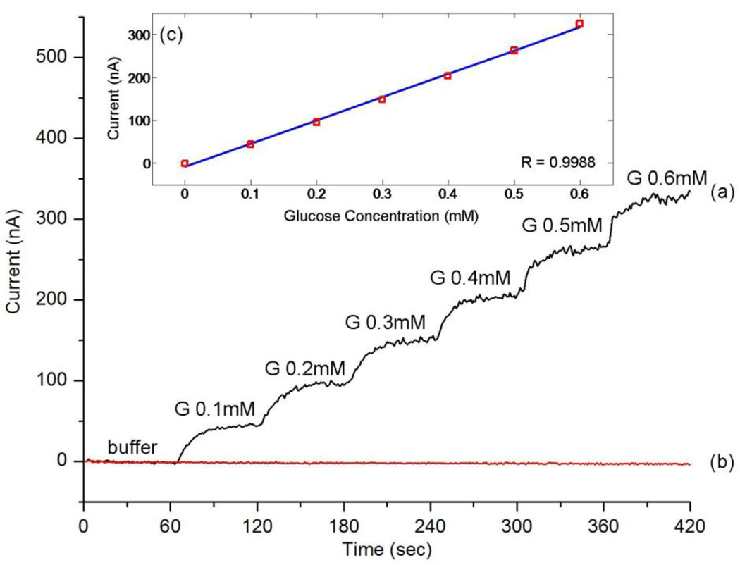
Fig. 3(a) shows a typical measured amperometric response acquired during successive addition of 0.1 mM glucose every 60 sec, which is approximately the minimum concentration in the eye surface tear film (Berman, 1991). The response is very quick, reaching 90% of the maximum value in less than 20 sec, which signifies the possibility of its practical application on a contact lens. Fig. 3(b) shows the control measurement curve acquired by successive addition of the same amount of buffer (no glucose) verifying the specificity of the sensor response. The calibration curve in Fig. 3(c) was generated by averaging current values of 30–50 sec after each addition. A linear relationship between the current and the glucose concentration was observed between 0.1 mM to 0.6 mM (R=0.9988).
Fig. 3.
Measured amperometric response and calibration curve of the sensor: (a) current signals for successive addition of 0.1 mM glucose (G); (b) current signals for the same amount of buffer (no glucose); (c) calibration curve for glucose signals generated by averaging current values of 30–50 sec after each addition.
Considering the small area of the working electrode (about 0.22 mm2), the sensitivity of our sensor is about 240 µAcm−2mM−1, higher than conventional disc electrodes with sol-gel film (Yu et al., 2003; Liang et al., 2008), and nanotube array sensors (Ekanavake et al., 2007). The good performance is due to both the micro-scale electrode design and the titania sol-gel film. The small electrode area and the branched working electrode design provide efficient diffusion conditions, whereas the sol-gel film results in a high enzyme loading efficiency due to its three-dimensional uniform porous network (Yu et al., 2003).
3.3. Selectivity and repeatability of the sensor
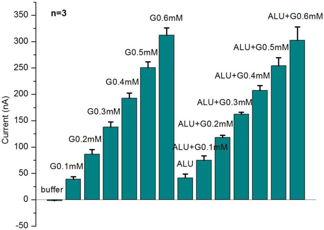
A typical amperometric test arrangement was used to validate the sensor operation. The measurement protocol consisted of successive additions of 0.1 mM glucose first in buffer and then in interference solution, which includes 50 µM ascorbic acid (A), 10 mM lactate (L) and 10 mM urea (U). Fig. 4 shows three independent measurement results from three different sensors. The current signals for each sensor were generated by averaging current values of 30–50 sec after each addition, the same as calibration value in Fig. 3(c).
Fig. 4.
Measured sensor repeatability and interference rejection. The results are based on typical amperometric measurements with three different sensors (n=3). The current signals here are generated by averaging current values of 30–50 sec after each addition. The interference solution ALU includes 50 µM ascorbic acid (A), 10 mM lactate (L) and 10 mM urea (U).
Our results indicate that the sensor has good interference rejection characteristics, which is attributed to the use of titanium isopropoxide and Nafion®. The small error bar for three sensors indicates good repeatability. Here, the concentrations of interferences ALU (A: ascorbic acid, L: lactate, U: urea) were chosen to exceed the maximum concentrations in tear fluid (Berman, 1991; Whikehart, 2003).
We can see that the current from ALU is almost the same as that from glucose 0.1 mM, so it is more difficult to accurately tell glucose from interferences for very low concentrations of glucose. Comparing the signal difference between glucose in buffer and glucose in interference solution at the same concentration, the difference is 93% for glucose 0.1 mM, and 37% for glucose 0.2 mM, but decreases to less than 20% for glucose more than 0.2 mM, which would be considered clinically accurate for practical measurement (Wilson and Gifford, 2005).
3.4. Detection limit of the sensor
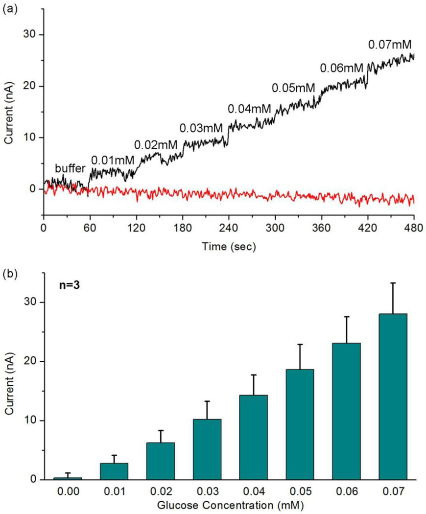
Fig. 5(a) shows the amperometric measurement results for very low concentrations of glucose 0.01–0.07 mM and Fig. 5(b) shows the calibration currents based on three different sensors, generated by averaging current values of 30–50 sec after each addition. The good linearity (R=0.9966) in Fig. 5(b) demonstrates that, in the absence of interfering species, our glucose sensor can detect a glucose concentration as low as 0.01 mM, which is 1/10 of the minimum concentration in tear film (Berman, 1991; Whikehart, 2003).
Fig. 5.
Measured amperometric response for very low concentrations (0.01–0.07 mM) of glucose: (a) the amperometric response for successive addition of 0.01 mM glucose and addition of the same amount of buffer; (b) calibration currents based on three different sensors (n=3). The current signals here are generated by averaging current values of 30–50 sec after each addition.
3.5. Stability of the sensor
In order to test the stability of our sensor for a long period, we have studied two cases concerning the storage of unused and used sensors. The unused sensor can retain its activity for one week if stored in buffer at 4 °C directly after preparation. The long lifetime is because the sol-gel film can prevent GOD from leaking out and the immobilization process does not influence the biological activity of enzyme, as reported (Yu et al., 2003; Liang et al., 2008).
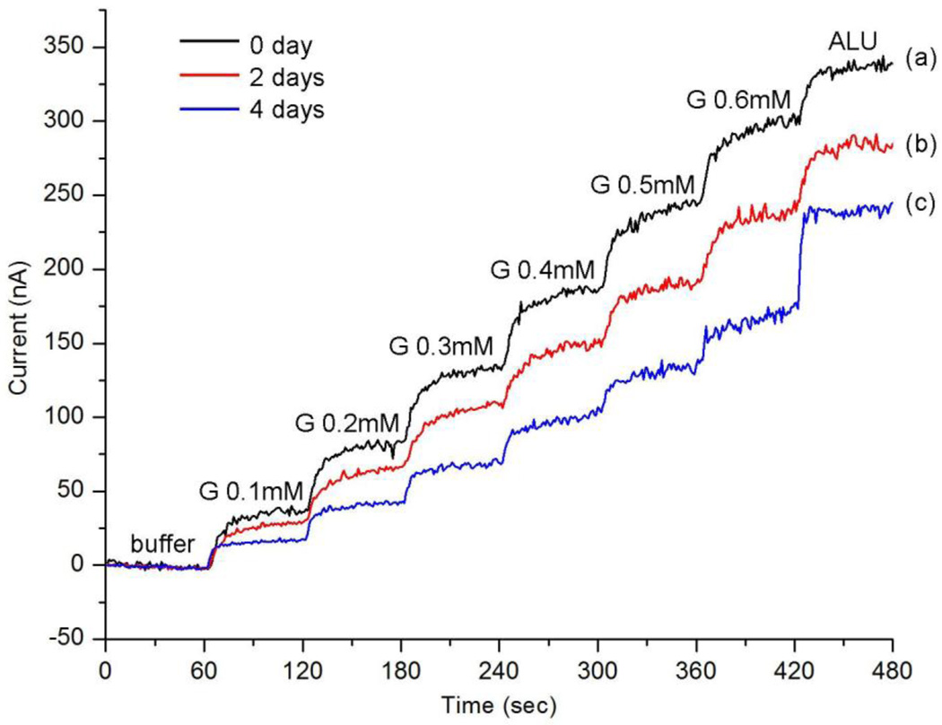
On the other hand, the activity of a used sensor decreases from measurement to measurement. The used sensor was stored in buffer at 4 °C between tests and used for about 2 h for each test. Fig. 6 shows the measurement results acquired from the same sensor tested three different times: directly after preparation, after 2 days, and after 4 days. It shows that: after 2 days the sensor can retain nearly 80% of its initial current response for glucose; after 4 days it can retain about 55% response for glucose, and at the same time the interference signal increases. The interesting similarity of Fig. 6(c) and Fig. 2(c) illustrates that after about 4 days, the sensor works analogously to the one just prepared with GOD/titania sol-gel film. Hence the decrease of current signals here is probably due to the Nafion® component leaching out of the GOD/titania/ Nafion® film during measurements. More research is needed to improve the stability of the sensor response over extended periods of time.
Fig. 6.
Measured amperometric response for glucose 0.1–0.6 mM for the same sensor: (a) right after preparation; (b) 2 days later; (c) 4 days later. The last step is the addition of the interference solution ALU, including 50 µM ascorbic acid (A), 10 mM lactate (L) and 10 mM urea (U).
4. Conclusions
A non-invasive continuous glucose sensor on a contact lens could make personalized medicine cheaper, simpler and more reliable. Here we successfully fabricated a micro-sized glucose sensor on a polymer contact lens. Pretreated with titania sol-gel film and Nafion® coating, the sensor exhibited a fast response, a high sensitivity and a good repeatability, in the range of low concentrations of glucose found in the tear film. Although many aspects remain to be improved, such as more efficient interference rejection, full biocompatibility for wearable contact lens, and integrating sensors with read-out and communication circuits, the results pave the way to build a multi-functional contact lens capable of chemical analysis in the future.
Acknowledgments
The authors express their gratitude to the National Science Foundation for support through EFRI grant number EFR0937710, as well as the National Institutes of Health by NHGRI grant number 7 P50HG002360-10.
Christian Marcheselli and Ramin Mirjalili are gratefully acknowledged for their help in developing the molding process for the contact lens, Andrew Lingley for his assistance in device microfabrication and Amanda Ghassaei for testing sensor prototypes.
Footnotes
Publisher's Disclaimer: This is a PDF file of an unedited manuscript that has been accepted for publication. As a service to our customers we are providing this early version of the manuscript. The manuscript will undergo copyediting, typesetting, and review of the resulting proof before it is published in its final citable form. Please note that during the production process errors may be discovered which could affect the content, and all legal disclaimers that apply to the journal pertain.
References
- Alexeev VL, Das S, Finegold DN, Asher SA. Photonic crystal glucose-sensing material for noninvasive monitoring of glucose in tear fluid. Clin. Chem. 2004;50:2353–2360. doi: 10.1373/clinchem.2004.039701. [DOI] [PubMed] [Google Scholar]
- Berman ER. Biochemistry of the eye. New York: 1991. p. 70. [Google Scholar]
- Brown FO, Lowry JP. Microelectrochemical sensors for in vivo brain analysis: an investigation of procedures for modifying Pt electrodes using Nafion. Analyst. 2003;128:700–705. doi: 10.1039/b300266g. [DOI] [PubMed] [Google Scholar]
- Baca JT, Taormina CR, Feingold E, Finegold DN, Grabowski JJ, Asher SA. Mass spectral determination of fasting tear glucose concentrations in nondiabetic volunteers. Clin. Chem. 2007a;53:1370–1372. doi: 10.1373/clinchem.2006.078543. [DOI] [PubMed] [Google Scholar]
- Baca JT, Finegold DN, Asher SA. Tear glucose analysis for the noninvasive detection and monitoring of diabetes mellitus. Ocul. Surf. 2007b;5:280–293. doi: 10.1016/s1542-0124(12)70094-0. [DOI] [PubMed] [Google Scholar]
- Clark L, Jr, Lyons C. Electrode systems for continuous monitoring in cardiovascular surgery. Ann. NY Acad. Sci. 1962;102:29–45. doi: 10.1111/j.1749-6632.1962.tb13623.x. [DOI] [PubMed] [Google Scholar]
- Cameron BD, Coté GL. Noninvasive glucose sensing utilizing a digital closed-loop polarimetric approach. IEEE Trans. Biomed. Eng. 1997;44:1221–1227. doi: 10.1109/10.649993. [DOI] [PubMed] [Google Scholar]
- Cheng W, Klauke N, Sedgwick H, Smith GL, Cooper JM. Metabolic monitoring of the electrically stimulated single heart cell within a microfluidic platform. Lab Chip. 2006;6:1424–1431. doi: 10.1039/b608202e. [DOI] [PubMed] [Google Scholar]
- Ekanayake E, Preethichandra D, Kaneto K. Polypyrrole nanotube array sensor for enhanced adsorption of glucose oxidase in glucose biosensors. Biosens. and Bioelectron. 2007;23:107–113. doi: 10.1016/j.bios.2007.03.022. [DOI] [PubMed] [Google Scholar]
- Fang A, Ng H, li S. A high-performance glucose biosensor based on monomolecular layer of glucose oxidase covalently immobilised on indium-tin oxide Surface. Biosens. and Bioelectron. 2003;19:43–49. doi: 10.1016/s0956-5663(03)00133-7. [DOI] [PubMed] [Google Scholar]
- Ferrante do Amaral CE, Wolf B. Current development in non-invasive glucose monitoring. Med. Eng. Phys. 2008;30:541–549. doi: 10.1016/j.medengphy.2007.06.003. [DOI] [PubMed] [Google Scholar]
- Heller A, Feldman B. Electrochemical glucose sensors and their applications in diabetes management. Chem. Rev. 2008;108:2482–2505. doi: 10.1021/cr068069y. [DOI] [PubMed] [Google Scholar]
- Iguchi S, Kudo H, Saito T, Ogawa M, Saito H, Otsuka K, Funakubo A, Mitsubayashi K. A flexible and wearable biosensor for tear glucose measurement. Biomed. Microdevices. 2007;9:603–609. doi: 10.1007/s10544-007-9073-3. [DOI] [PubMed] [Google Scholar]
- Kagie A, Bishop DK, Burdick J, La Belle JT, Dymond R, Felder R, Wang J. Flexible rolled thick-film miniaturized flow-cell for minimally invasive amperometric sensing. Electroanalysis. 2008;20:1610–1614. [Google Scholar]
- LeBlanc JM, Haas CE, Vicente G, Colon LA. Evaluation of lacrimal fluid as an alternative for monitoring glucose in critically ill patients. Intensive Care Med. 2005;31:1442–1445. doi: 10.1007/s00134-005-2747-5. [DOI] [PubMed] [Google Scholar]
- Liang R, Jiang J, Qiu J. An amperometric glucose biosensor based on titania sol-gel/Prussian blue composite film. Anal. Sci. 2008;24:1425–1430. doi: 10.2116/analsci.24.1425. [DOI] [PubMed] [Google Scholar]
- Li C, Ahn CH, Shutter LA, Narayan RK. Toward real-time continuous brain glucose and oxygen monitoring with a smart catheter. Biosens. and Bioelectron. 2009;25:173–178. doi: 10.1016/j.bios.2009.06.032. [DOI] [PubMed] [Google Scholar]
- Maruo K, Tsurugi M, Chin J, Ota T, Arimoto H, Yamada Y, Tamura M, Ishii M, Ozaki Y. Noninvasive blood glucose assay using a newly developed nearinfrared system. IEEE J. Selected Top. Quantum Electron. 2003;9:322–330. [Google Scholar]
- March WF, Mueller A, Herbrechtsmeier P. Clinical trial of a noninvasive contact lens glucose sensor. Diabetes Technol. Ther. 2004;6:782–789. doi: 10.1089/dia.2004.6.782. [DOI] [PubMed] [Google Scholar]
- Miyashita M, Ito N, Ikeda S, Murayama T, Oguma K, Kimura J. Development of urine glucose meter based on micro-planer amperometric biosensor and its clinical application for self-monitoring of urine glucose. Biosens. and Bioelectron. 2009;24:1336–1340. doi: 10.1016/j.bios.2008.07.072. [DOI] [PubMed] [Google Scholar]
- Stauth SA, Parviz BA. Self-assembled single-crystal silicon circuits on plastic. Proc. Natl Acad. Sci. USA. 2006;103:13922–13927. doi: 10.1073/pnas.0602893103. [DOI] [PMC free article] [PubMed] [Google Scholar]
- Saeedi E, Kim S, Parviz BA. Self-assembled crystalline semiconductor optoelectronics on glass and plastic. J. Micromech. Microeng. 2008;18:075019. [Google Scholar]
- Tierney MJ, Jayalakshmi Y, Parris NA, Reidy MP, Uhegbu C, Vijayakumar P. Design of a biosensor for continual, transdermal glucose monitoring. Clin. Chem. 1999;45:1681–1683. [PubMed] [Google Scholar]
- Whikehart DR. Biochemistry of the eye. second ed. Boston: Butterworth-Heinemann; 2003. p. 12. [Google Scholar]
- Wilson G, Gifford R. Biosensors for real-time in vivo measurements. Biosens. and Bioelectron. 2005;20:2388–2403. doi: 10.1016/j.bios.2004.12.003. [DOI] [PubMed] [Google Scholar]
- Yeh SJ, Hanna CF, Khalil OS. Monitoring blood glucose changes in cutaneous tissue by temperature-modulated localized reflectance measurements. Clin. Chem. 2003;49:924–934. doi: 10.1373/49.6.924. [DOI] [PubMed] [Google Scholar]
- Yu J, Liu S, Ju H. Glucose sensor for flow injection analysis of serum glucose based on immobilization of glucose oxidase in titania sol-gel membrane. Biosens. and Bioelectron. 2003;19:401–409. doi: 10.1016/s0956-5663(03)00199-4. [DOI] [PubMed] [Google Scholar]


