

Abstract
Background: Orthopedic trauma care relies on two-dimensional radiograms both before and during the operation. Understanding the three-dimensional nature of complex fractures on plain radiograms is challenging. Modern fluoroscopes can acquire three-dimensional volume datasets even during an operation, but the device limitations constrain the acquired volume to a cube of only 12-cm edge. However, viewing the surrounding intact structures is important to comprehend the fracture in its context. We suggest merging a fluoroscope’s volume scan into a generic bone model to form a composite full-length 3D bone model. Methods: Materials consisted of one cadaver bone and 20 three-dimensional surface models of human femora. Radiograms and computed tomography scans were taken before and after applying a controlled fracture to the bone. A 3D scan of the fracture was acquired using a mobile fluoroscope (Siemens Siremobil). The fracture was fitted into the generic bone models by rigid registration using a modified least-squares algorithm. Registration precision was determined and a clinical appraisal of the composite models obtained. Results: Twenty composite bone models were generated. Average registration precision was 2.0 mm (range 1.6 to 2.6). Average processing time on a laptop computer was 35 s (range 20 to 55). Comparing synthesized radiograms with the actual radiograms of the fractured bone yielded clinically satisfactory results. Conclusion: A three-dimensional full-length representation of a fractured bone can reliably be synthesized from a short scan of the patient’s fracture and a generic bone model. This patient-specific model can subsequently be used for teaching, surgical operation planning, and intraoperative visualization purposes.
Key words: 3D Imaging (imaging, three-dimensional); bone and bones; fluoroscopy; teaching; tomography; x-ray computed; clinical application; orthopedic surgery; operation planning; composite bone model
INTRODUCTION
Two-dimensional radiograms are the standard imaging method for diagnosing extremity injuries in orthopedic trauma. The obtained orthogonal radiograms are also commonly used for preoperative surgical planning.1,2 Particularly with complex fractures, it is important that the surgeon comprehend the “personality” of the fracture.2 Correct three-dimensional (3D) understanding of the fracture morphology is essential and improves the overall result of the operative procedure.3 Orthogonal radiograms, however, only insufficiently depict the true configuration of a complex fracture. Formerly, surgical residents would gain understanding of fracture morphology by comparing the plain radiograms with the actual fracture configuration found during open surgery. However, in minimally invasive surgical procedures, the entire fracture site is not exposed anymore. Instead, fracture reduction and fixation is performed through short skin incisions. The progress is monitored using mobile radiography devices (fluoroscopes) in the operation room, once again using 2D images. The junior surgeons’ opportunities to actually visualize a fracture during the operation, thus, decline with increasing number of minimally invasive procedures. Under these circumstances, the availability of 3D image data gains importance.
Mobile fluoroscopes can be a viable alternative to computed tomography (CT) for acquisition of volume datasets. Modern fluoroscopes not only acquire 2D radiograms but also provide 3D data acquisition functionality directly in the operation room.4–6 The field of view of these 3D scans is, however, very restricted. Because of limitations in the size of the fluoroscope’s detector panel, the 3D scan only yields a cube of approximately 12 × 12 × 12 cm. Thus, although it is possible to gain 3D data of the fracture site itself, the surrounding intact bone structures are ignored. This can be misleading.
Lack of 3D image data results in poor understanding of a fracture’s 3D morphology. This is a serious issue in current trauma surgery training. We therefore suggest synthesizing a customized bone model by integrating the patient-specific fracture into a generic full-length 3D bone model. Merging these two components forms a composite three-dimensional model that presents a realistic depiction of the entire fractured bone (Fig. 1). This model can subsequently be employed for teaching purposes and for preoperative surgical planning.
Fig 1.

The volume acquired by a 3D capable fluoroscope is only approximately 12 × 12 × 12 cm (gray cube) and does not cover the entire bone. Assembling the fluoroscope’s 3D scan of the fracture with a generic bone model synthesizes a full-length composite bone model.
The hypothesis of this study is that digitally merging a short scan of a fracture into a generic bone model creates a realistic composite 3D bone model of the entire affected bone. The concept of assembling the fracture site and the intact surrounding bone is demonstrated and validated on human femoral bones. Deployment scope and relevance of composite models in orthopedic trauma surgery are subsequently discussed.
MATERIALS AND METHODS
Image Acquisition
The study materials consisted of one fresh cadaver femur dedicated to clinical research and 20 preprocessed surface models of human femoral bones obtained from the AO bone database.7 The AO bone database comprises a diverse selection of bone models obtained from full-length postmortem bone scans. The scans are manually segmented by the AO Development Institute to create high quality 3D models that accurately reflect the inter-individual morphological variations.
Institutional Reviewing Board approval was obtained before commencing the study. The cadaver femur was carefully exarticulated and stripped of soft tissues. Orthogonal full-length radiograms were taken using an underlaid marker plate8 to facilitate subsequent scaling and measurement. A full-length CT scan of the bone was acquired on a medical scanner (Somatom 16, Siemens Medical AG, Erlangen/Germany) in high resolution (slice thickness 1 mm, 75 kV, 512 × 512 pixels resolution). A controlled mid-shaft fracture was then applied to the femur. The dislocated fragments were fixed in radio-translucent insulation foam to conserve the original fracture configuration. Both the orthogonal radiograms and the full-length CT scan were repeated on the fractured bone. In addition, 3D scans of the fracture were acquired using a 3D-capable mobile fluoroscope (Siemens Siremobil ISO-C 3D, Siemens Medical). Triangulated surface models were created from the DICOM image stacks by applying intensity threshold discrimination and a marching cube algorithm.9 The triangulated surface meshes obtained from the 3D fluoroscope and CT scans were stored in STL format (stereolithography) for subsequent processing. Both the fracture and the generic bone model originate from DICOM standard images and are thus based on metric units. Consequently, no additional scaling is necessary.
Image Processing
Figure 2 depicts the general concept of creating the patient-specific composite bone model. The processing sequence is as follows. (a) Determine bone length and approximate position of the fracture, in respect to the bone length, on the plain radiographs. (b) Select a comparable generic bone model from a set of generic bones using morphometric criteria. (c) Acquire a 3D scan of the fracture site on a 3D-capable fluoroscope. (d) Digitally merge the fracture into the selected generic bone model.
Fig 2.

Concept of composite bone model synthesis. (a) The bone morphology and gross fracture localization are determined on a plain radiogram. (b) The most appropriate 3D model is selected from a set of generic bone models. (c) A 3D scan of the fracture is acquired on a mobile 3D-capable fluoroscope. Restricting the scan to just the fracture site limits radiation exposure. (d) The generic 3D bone and the actual fracture site are digitally assembled to form a composite 3D model.
The approximate position of the fracture is determined on a full-length antero-posterior radiogram of the bone. An underlaid reference panel containing a grid of radio-opaque markers serves as scaling aid. The straight-line distance from the proximal (p) and distal (d) ends of the bone up to the closest fracture line is measured on the radiogram. These distances are then transferred to the generic 3D bone model where they serve as first estimate the patient-specific fracture’s position. Based on these seed values, the best fit is determined with an iterative closest point algorithm.10,11 The assumption is that the 3D fracture scan contains a “collar” of intact bone shaft on each side of the fracture. These intact shaft portions are matched to the corresponding region on the generic bone shaft. The optimal translation and rotation matrices are determined independently for the proximal and distal intact shaft portions. The transformation matrices are subsequently applied to the generic bone parts to synthesize the composite 3D bone model.
All processing and visualization was performed using Matlab 2006b software (Mathworks, Natick, MA/USA) using specially programmed scripts. Computations were performed on an Apple Macbook Pro laptop computer (Intel (R) Core2 Duo 2 GHz processor, 2 GB RAM, Windows XP). To accelerate computation, all generic bones’ surface meshes were reduced to 60,000–90,000 vertices.
Visualization and Analysis
Initially, a composite bone model was prepared in which the fracture was fitted back into the model of the same cadaver bone as scanned in its still unfractured state. Subsequently, the fracture was merged with 20 generic surface models of human femora. To validate fitting accuracy, the mean registration error per point was computed. This is the minimized total registration error divided by number of vertices employed for registration. Besides this merely computational approach, a more clinically relevant assessment was performed. Virtual radiographs of the composite bone model were generated, in antero-posterior and lateral projections, corresponding to the radiogram projections routinely employed in clinical practice. Three experienced trauma surgeons appraised the axial alignment in both viewing planes. Criteria for comparing the virtual radiograms of the composite model to the original radiographs of the fractured bone were: fracture position, axial and rotational alignment, and overall quality of the composite model. Each criterion was rated on a scale from 1 through 5 ranging from extremely unsatisfactory to entirely satisfactory. Finally, the robustness of the method was evaluated by artificially introducing an imprecision in the manual measurement of the fracture location on the radiograph. With one generic model, the fracture’s distance (p) and (d) from the proximal and distal bone ends were varied ±15 mm in 5-mm intervals. The algorithm was tested to ascertain how it positioned the fracture on the generic bone based on this less concise matching zone. The resulting composite models were overlaid and visually evaluated for congruence.
RESULTS
Figure 3 depicts the intermediate steps described in the composite bone-model schematic. The rigid registration algorithm required an average of 35 s (range 20 to 55 s) computation time to compile a composite model. Table 1 is an extract of the rigid registration precision assessment. Computational precision is shown as the mean distance between a point (vertex) on the fracture site’s collar to the closest point on the generic bone shaft. Overall matching precision was 2.0 mm (range 1.6 to 2.6). Figure 4 shows a selection of composite bone models synthesized during the study. The fracture site was matched with five different generic femur models, thus, generating five very similar composite models. Only the joint regions vary slightly because of morphological differences in the generic bones themselves. Figure 5 shows a comparison of the fractured bone’s radiograms with virtual radiograms created from 3D surface models. The composite model very precisely replicates the actual radiograms in the two standard antero-posterior and lateral projections. Clinical appraisal of the images yielded positive results. Clinicians awarded an average of 4.8 and 4.6 grade points (maximum of 5) for rotational and axial alignment, respectively. Fracture position was equally highly valued with 4.8 grade points. Overall score was 4.7 grade points.
Fig 3.

Processing steps during generation of a composite 3D bone model. (a) The approximate location of the fracture is determined on the radiogram. (b) A generic intact bone model is cut accordingly. (c) A 3D model of the fracture site obtained from the 3D fluoroscopy scan and the collar of intact bone shaft isolated on each side of the fracture (images magnified). (d) The collars from the fracture scan are matched to the generic bone model by rigid registration. The composite 3D model is created by independently applying the determined transformation matrices to both ends of the generic bone model (b).
Table 1.
Rigid Registration Error when Merging a 3D-Fluoro Scan with Generic Models Using an Iterative Closest Point Algorithm
| Matching Proximal Zone of Fracture | Matching Distal Zone of Fracture | ||||||
|---|---|---|---|---|---|---|---|
| Mean | Median | SD | Mean | Median | SD | ||
| Self | 1.753 | 1.523 | 0.591 | Self | 1.303 | 1.261 | 0.499 |
| 1 | 2.211 | 2.022 | 1.115 | 1 | 2.101 | 2.098 | 0.858 |
| 2 | 2.170 | 2.115 | 0.853 | 2 | 1.744 | 1.672 | 0.717 |
| 3 | 1.666 | 1.607 | 0.688 | 3 | 1.942 | 1.874 | 0.758 |
| 4 | 2.079 | 2.050 | 0.851 | 4 | 1.822 | 1.760 | 0.768 |
| 5 | 1.834 | 1.693 | 0.856 | 5 | 2.089 | 2.066 | 0.790 |
| 6 | 2.114 | 2.023 | 0.894 | 6 | 2.522 | 2.354 | 1.073 |
| 7 | 1.844 | 1.718 | 0.861 | 7 | 1.993 | 1.95 | 0.780 |
| 8 | 2.414 | 2.272 | 1.107 | 8 | 1.729 | 1.674 | 0.709 |
| 9 | 1.730 | 1.664 | 0.767 | 9 | 1.885 | 1.842 | 0.735 |
| 10 | 2.333 | 2.066 | 1.268 | 10 | 1.829 | 1.770 | 0.741 |
| 11 | 2.336 | 2.194 | 1.012 | 11 | 1.637 | 1.583 | 0.662 |
| 12 | 1.908 | 1.836 | 0.812 | 12 | 1.911 | 1.765 | 0.915 |
| 13 | 2.395 | 2.284 | 1.088 | 13 | 2.331 | 2.35 | 0.619 |
| 14 | 2.492 | 2.262 | 1.311 | 14 | 2.028 | 1.904 | 0.894 |
| 15 | 2.417 | 1.738 | 1.966 | 15 | 1.858 | 1.773 | 0.721 |
| 16 | 2.438 | 2.317 | 1.054 | 16 | 1.981 | 1.916 | 0.834 |
| 17 | 2.080 | 1.977 | 0.941 | 17 | 2.265 | 2.121 | 1.080 |
| 18 | 1.849 | 1.734 | 0.860 | 18 | 2.622 | 2.453 | 1.152 |
| 19 | 1.927 | 1.859 | 0.767 | 19 | 1.734 | 1.69 | 0.686 |
| 20 | 2.419 | 2.275 | 1.161 | 20 | 1.755 | 1.664 | 0.779 |
The mean error is expressed in mm distance between a point (vertex) on intact collar adjacent to the fracture and the closest point in the corresponding region on the generic bone shaft. The proximal and distal collars are evaluated separately. “Self” is a match of the fracture back into a surface model created from its own intact bone.
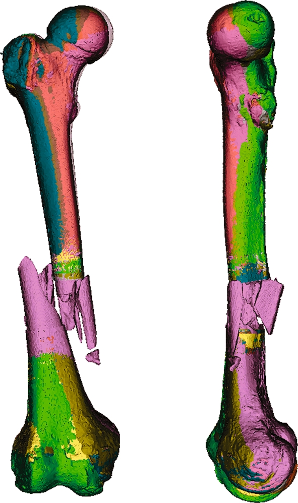
Fig 4.

Results of matching the fracture site into different intact generic bone models. Each generic bone has its characteristic morphology. The matching algorithm is robust enough to account for variable surface mesh resolution, inhomogeneous shaft diameters and differing cross-sections.
Fig 5.

Comparison of genuine and virtual radiograms. (a) Orthogonal radiograms of the fractured bone. (b) Virtual radiogram synthesized from a 3D model of a full-length CT scan of the fractured bone. (c) Virtual radiogram of the composite model composed of the fracture scan merged (arrows) into an intact generic femur model. The composite model shows high congruence with the reference images in a and b.
DISCUSSION
Best Available Technology for Surgical Planning
Long bones are common sites for complex fractures in both young and elderly patients.12 Conventional two-dimensional (2D) radiography remains the most commonly used imaging method in orthopedic trauma patient care. Radiograms are routinely acquired for diagnostic purposes and subsequently employed for 2D operation planning by overlaying transparent film templates of the implants.2 However, because of their three-dimensional nature, complex fractures cannot be accurately interpreted on two-dimensional projections.13–18 For joint fractures, a volumetric dataset is usually acquired by CT scan.4–6,19–22 A 3D model can be reconstructed from the volumetric dataset and employed for computer-assisted surgical planning and implant placement.23–25 However, even complex fractures located in the shaft of long bones are not usually scanned to avoid excessive radiation exposure. It is important that the surgeons comprehend a shaft fracture’s morphology before and during the surgical intervention. During their training, young surgeons can be misled by the 2D fracture projections on plain radiograms. Training requires an iterative process of comparing 2D radiographs to the 3D morphology seen when assisting senior staff performing open surgery. This learning opportunity is disappearing with increasing deployment of minimal-invasive procedures. A surgical trainee nowadays rarely sees the true 3D configuration of the shaft fracture being treated. Nonetheless, trauma surgeons must train their skills in reading 2D images and interpreting those to form a mental 3D impression of the fracture.
Modern 3D-capable fluoroscopes offer volumetric fracture scanning with lower radiation exposure than CT scanners, albeit with lower image resolution and contrast. 3D-fluoroscopy has the advantage that it can be obtained both before and during a surgical procedure.19,20,22 The 3D fluoroscopy scan is, however, limited to the fracture site and only marginally depicts the surrounding intact bone. This limitation is due to the small size of the detector panel in mobile fluoroscopes. The acquired volume is restricted to a 12 × 12 × 12-cm cube. However, both for teaching purposes and for computer-assisted preoperative surgical planning, a 3D model of the fracture including the surrounding is required. Indeed, the implant must bridge the comminuted zone and be anchored in solid bone on both sides of the fracture to ensure appropriate fracture stabilization.1–3,24 Altogether, 3D preoperative planning of long bone fractures is presently unsatisfactory for lack of appropriate 3D image data.
Composite Bone Model
We suggest scanning just the fracture zone and merging this short scan with a full-length model of a generic bone. Thereby, a 3D model very similar to the affected bone can be obtained without exposing the patient to unnecessary radiation. Preparatory work includes in vitro high-resolution full-length CT scans of multiple cadaver bones. The surface models are then parameterized and subsequently stored in a bone database.7 The bone model that best corresponds to the patient’s anatomy is then retrievable from the database. A method to select a corresponding 3D model of the proximal femur, based on orthogonal 2D images, has been published previously.26 Our investigation goes one step further and describes how the selected generic 3D bone models can be employed to actually improve patient care. The described approach uses standard rigid registration algorithms10,11 to fit a model of the patient’s fracture into that of an intact bone. Iterative closest point algorithms have been utilized for many years. In this study, we have further customized the algorithms to solve an important clinical problem in orthopedic trauma patient care: three-dimensional visualization of a fracture in the context of the surrounding bone. The novel patient-specific composite bone model we present can be used for simulation, education, preoperative planning, and intraoperative control of axis and rotation.
Precision and Feasibility
In our preliminary studies, we merged one femoral shaft fracture into 20 different full-length femur models. This approach was chosen to ensure that the matching would be sufficiently robust to create acceptable results irrespective of which generic bone model would be chosen from a bone database. Depending on the criteria used to select the generic bone model from the database, the proximal and distal intact bone portions may in fact originate from separate generic models. The composite bone model is then assembled out of three distinct parts: distal intact bone from generic model 1—patient-specific fracture scan—proximal intact bone from generic model 2.
The iterative closest point algorithm was highly effective in merging the fracture into all of the 20 generic bone models. The computations, however, did not yield a 100% fit even for the ideal match of the fracture back into a model generated from the very same bone. Even in this ideal example, there is a residual absolute registration error. The residual error is influenced by three factors: (1) the volume dataset acquired from 3D fluoroscopic scanning is subject to non-linear distortion effects. Distortion increases eccentrically towards the periphery of the acquired cube and occurs in all three dimensions. The fracture should be well centered in the scan volume to allow for intact shaft on both sides. Thus, the intact shaft “collars” used for matching are located precisely in the distorted peripheral volume. Therefore, an unavoidable error is introduced even when using theoretically fully compatible models. (2) The 3D-fluoro scan and the CT scan have different resolutions and grayscales. This can influence threshold segmentation and result in incongruent surface models of one and the same object. Therefore, there is no 1:1 correspondence of vertices on the objects being matched. Decimating surface models before matching can further add to the computational imprecision. (3) The iterative closest point algorithm can terminate in a local minimum. This would result in suboptimal results independently of the other factors. Even diligent manual selection of the approximate matching zone cannot completely avoid this problem.
The mean registration error increases further when heterogeneous bone models are matched. This is the case when the fracture is merged into a generic model selected from a database. This is primarily explained by the varying diameters and forms of the shaft cross-section. The morphological characteristics of the specific bone depend on several factors, e.g., gender, age, ethnicity, etc. In this study, we probed multiple generic bone models and found that the registration error could itself be a differentiator for selecting the best-matching generic model. Indeed, the ideal match (self) could easily be identified as having the least variance in registration error (Table 1).
The clinicians’ favorable evaluation indicates that computationally determined average registration errors of 1 to 3 mm are not clinically relevant. Indeed, the computational registration error does not represent a mismatch in only one direction or axis. The composite model can therefore be overall well aligned despite a seemingly high average of point-to-point registration errors. Figure 5 illustrates the good congruence and reproducibility of composite models synthesized from different generic bones.
Feasibility
The necessity to manually determine the approximate position of the fracture site on plain radiograms is somewhat inconvenient. However, this procedure barely requires a few minutes. In this study, we employed an underlaid absolute reference panel with a grid of radio-opaque markers8 to scale the radiograms before measuring the fracture position. A more readily available scaling alternative is to place a lead bead of known diameter next to the bone during radiography. Also, newer digital radiography devices offer built-in scaling and even some simple distance and angle measurement tools. The process of manually determining the fracture position is thus largely simplified on a digital radiogram.
Determining the initial fracture insertion site is subject to slight scaling errors due to radiogram projection effects and, more importantly, manual imprecision. Our algorithm proved to be robust enough to compensate an error of up to 15 mm in the approximate position of the fracture (Fig. 6). This is explained by the femur shaft not being a true cylinder. Firstly, the femur shaft has a somewhat conical shape that narrows towards the mid-shaft. Secondly, the femur shaft’s cross-section can be described as resembling a teardrop with varying proportions at different heights along the bone. Consequently, the shaft’s morphological features facilitate computing the correct position of the fracture and the rotational alignment. Nevertheless, feeding good starting points, and thus restricting the matching zone on the generic bone model, improves reliability and speed. Computational time of less than a minute could be achieved even on a laptop computer.
Fig 6.
Seven superposed composite models. In this example, the manually measured position of the fracture within the shaft was intentionally varied in 5-mm steps to ±15 mm. The algorithm is robust enough to largely correct such an imprecision. This is demonstrated in the only minor deviations between the individually colored composite models.
Deployment Scope
We envisage two distinctive deployment scenarios: The first scenario employs the composite model for preoperative planning. The fracture is diagnosed on conventional 2D radiograms. Then, either a short CT scan or a 3D fluoroscopy scan of the fracture site is acquired. A surface model of the fracture is derived from the volumetric dataset and merged into a generic bone model. The composite model is then employed for operation planning which includes implant selection and tentative implant positioning and anchoring. Before implant positioning, appropriate reduction and bone length restoration should be verified. This can be done by comparing the virtual fracture reduction result with a radiogram or scanogram of the contra-lateral intact bone.
The second scenario plays in the operation theater during the operation itself. A 3D scan of the fracture site is acquired using a mobile 3D-capable fluoroscope. The C-arm thereby rotates around the operation table and sterile draping. The fracture fragments’ position after surgical reduction can be verified on the 3D scan itself. However, the bone axes and the rotational alignment of the bone after reduction cannot be easily determined because of the fluoroscope’s limited field of view. Rotation and alignment can be more easily verified on the composite model of the entire bone, as anatomical landmarks that help determining orientation are more prominent at the bone’s ends than on its shaft. The true axes and rotation of the entire bone can then be determined using simple vector geometry functions. We suggest that in the future, all mobile 3D fluoroscopes feature integrated composite bone model functionality.
This study is a proof of concept for patient-specific 3D composite bone model generation. The method is demonstrated on the femoral shaft but can also be employed on other anatomical regions, for example lower limb, forearm, and others. The composite bone model method is also not limited by age, gender, or ethnicity of the patient. The only prerequisite is that appropriate generic bone models of those patient groups are available in the bone database.
Limitations
A limitation of the proposed method is the necessity to have an overlapping collar of 10 to 20 mm intact bone shaft on each side of the fracture in the 3D scan. The edge length of 3D volume acquired by the mobile fluoroscope is, however, limited to 120 mm. Thus, the fracture may not exceed 80 to 100 mm total length, leaving the remaining 10 to 20 mm on each side as intact shaft necessary for matching to the generic 3D model. Longer fractures could nevertheless be used for composite modeling. In such a scenario, a two-step approach would be taken. First, two slightly overlapping scans of the fracture would be acquired. As the fracture has a unique configuration, the overlapping scans could be fitted to form a larger compounded fracture model of up to 200-mm length. This compounded fracture model would then have a broader intact bone collar on each side of the fracture. It could, thus, more easily and more precisely be merged into the generic bone model. We are currently investigating pre-compounding of two 3D-fluoro scans.
CONCLUSIONS
Iterative closest point matching is an efficient method to merge a short fracture scan with a generic 3D bone model. The resulting patient-specific composite bone model is a sufficiently realistic depiction of the entire affected bone to be used for teaching purposes. It can also be imported into 3D planning software and employed for preoperative surgical planning. The composite model can further be employed to intraoperatively verify bone axes after surgical fracture reduction and before applying the internal fixation. We expect that patient-specific composite bone models will ultimately improve trauma patient care by enhancing teaching, promoting 3D preoperative planning and facilitating intraoperative verification of fracture reduction.
Acknowledgments
The authors thank the following for contributing to this study: Department of Pathology, University Hospital of Basel/Switzerland (Prof. M.J. Mihatsch and Ralf Schoch) for supplying the bone specimen. Department of Radiology, University Hospital, Basel/Switzerland (Ms Severin Dziergwa) for performing repeated computed tomography scans. The AO Research Institute, Davos/Switzerland (Dr. Karsten Schwieger and Mr. Boyko Gueorguiev) for assisting in creating a controlled bone fracture. The AO Development Institute, Davos/Switzerland (Dr. Hanspeter Noser) for granting access to the AO bone database. The AO bone database is available to partner institutes for dedicated research projects. This study was co-funded by the Robert Mathys Foundation, Bettlach/Switzerland (Grant E06-0001) and a donation from Mrs M. Täsch Furger, Stäfa/Switzerland.
References
- 1.Müller KH, Strosche H, Scheuer I. Plate osteosynthesis in posttraumatic deformities of the femoral shaft. Arch Orthop Trauma Surg. 1984;103:303–319. doi: 10.1007/BF00432418. [DOI] [PubMed] [Google Scholar]
- 2.Rüedi TP, Buckley RE, Moran CG: AO Principles of Fracture Management, Second expanded edition (2007), Stuttgart: Thieme, 2006
- 3.Messmer P, Long G, Suhm N, Hehli M, Wirth J, Regazzoni P, Jacob AL. Three-dimensional fracture simulation for preoperative planning and education. Eur J Trauma. 2001;27:171–177. [Google Scholar]
- 4.Kotsianos D, Wirth S, Fischer T, Euler E, Rock C, Linsenmaier U, Pfeifer KJ, Reiser M. 3D imaging with an isocentric mobile C-arm comparison of image quality with spiral CT. Eur Radiol. 2004;14:1590–1595. doi: 10.1007/s00330-004-2316-2. [DOI] [PubMed] [Google Scholar]
- 5.Wirth S, Euler E, Linsenmaier U, Heining SM, Kotsianos D, Pfeifer KJ, Mutschler W, Reiser M. C-arm-based mobile computed tomography: a comparison with established imaging on the basis of simulated treatments of talus neck fractures in a cadaveric study. Comput Aided Surg. 2004;9:27–38. doi: 10.1080/10929080400006309. [DOI] [PubMed] [Google Scholar]
- 6.Richter M, Geerling J, Zech S, Goesling T, Krettek C. Intraoperative three-dimensional imaging with a motorized mobile C-arm (SIREMOBIL ISO-C-3D) in foot and ankle trauma care: a preliminary report. J Orthop Trauma. 2005;19:259–266. doi: 10.1097/01.bot.0000151822.10254.db. [DOI] [PubMed] [Google Scholar]
- 7.Messmer P, Matthews F, Jacob AL, Kikinis R, Regazzoni P, Noser H. A CT database for research, development and education: concept and potential. J Digit Imaging. 2007;20:17–22. doi: 10.1007/s10278-006-0771-9. [DOI] [PMC free article] [PubMed] [Google Scholar]
- 8.Messmer P, Matthews F, Wullschleger C, Huegli R, Regazzoni P, Jacob AL. Image fusion for intraoperative control of axis in long bone fracture treatment. Eur J Trauma. 2006;6:555–561. doi: 10.1007/s00068-006-5159-5. [DOI] [Google Scholar]
- 9.Lorensen WE, Cline HE. Marching cubes: a high resolution 3D surface construction algorithm. Comput Graph. 1987;21:163–169. doi: 10.1145/37402.37422. [DOI] [Google Scholar]
- 10.Besl PJ, McKay ND. A method for registration of 3-D shapes. IEEE Trans Pattern Anal Mach Intell. 1992;14:239–255. doi: 10.1109/34.121791. [DOI] [Google Scholar]
- 11.Estepar RSJ, Brun A, Westin CF: Robust generalized total least squares iterative closest point registration. MICCAI, LNCS 3216:234–241, 2004
- 12.Urquhart DM, Edwards ER, Graves SE, Williamson OD, McNeil JJ, Kossmann T, Richardson MD, Harrison DJ, Hart MJ, Cicuttini FM. Characterisation of orthopaedic trauma admitted to adult level 1 trauma centres. Injury. 2006;37:120–127. doi: 10.1016/j.injury.2005.10.016. [DOI] [PubMed] [Google Scholar]
- 13.Krettek C, Schandelmaier P, Miclau T, Bertram R, Holmes W, Tscherne H. Transarticular joint reconstruction and indirect plate osteosynthesis for complex distal supracondylar femoral fractures. Injury. 1997;28(Suppl 1):A31–A41. doi: 10.1016/S0020-1383(97)90113-3. [DOI] [PubMed] [Google Scholar]
- 14.Marschollek M, Teistler M, Bott OJ, Stuermer KM, Pretschner DP, Dresing K. Pre-operative dynamic interactive exploration of complex articular fractures using a novel 3D navigation tool. Methods Inf Med. 2006;45:384–388. [PubMed] [Google Scholar]
- 15.Rieger M, Gabl M, Gruber H, Jaschke WR, Mallouhi A. CT virtual reality in the preoperative workup of malunited distal radius fractures: preliminary results. Eur Radiol. 2005;15:792–797. doi: 10.1007/s00330-004-2353-x. [DOI] [PubMed] [Google Scholar]
- 16.Wicky S, Blaser PF, Blanc CH, Leyvraz PF, Schnyder P, Meuli RA. Comparison between standard radiography and spiral CT with 3D reconstruction in the evaluation, classification and management of tibial plateau fractures. Eur Radiol. 2000;10:1227–1232. doi: 10.1007/s003300000326. [DOI] [PubMed] [Google Scholar]
- 17.Woolson ST, Dev P, Fellingham LL, Vassiliadis A: Three-dimensional imaging of bone from computerized tomography. Clin Orthop Relat Res:239–248, 1986 [PubMed]
- 18.Doornberg J, Lindenhovius A, Kloen P, Dijk CN, Zurakowski D, Ring D. Two and three-dimensional computed tomography for the classification and management of distal humeral fractures. Evaluation of reliability and diagnostic accuracy. J Bone Joint Surg Am. 2006;88:1795–1801. doi: 10.2106/JBJS.E.00944. [DOI] [PubMed] [Google Scholar]
- 19.Braten M, Tveit K, Junk S, Aamodt A, Anda S, Terjesen T. The role of fluoroscopy in avoiding rotational deformity of treated femoral shaft fractures: an anatomical and clinical study. Injury. 2000;31:311–315. doi: 10.1016/S0020-1383(99)00299-5. [DOI] [PubMed] [Google Scholar]
- 20.Heiland M, Schmelzle R, Hebecker A, Schulze D. Intraoperative 3D imaging of the facial skeleton using the SIREMOBIL Iso-C3D. Dentomaxillofac Radiol. 2004;33:130–132. doi: 10.1259/dmfr/15309653. [DOI] [PubMed] [Google Scholar]
- 21.Heiland M, Schulze D, Adam G, Schmelzle R. 3D-imaging of the facial skeleton with an isocentric mobile C-arm system (Siremobil Iso-C3D) Dentomaxillofac Radiol. 2003;32:21–25. doi: 10.1259/dmfr/80391180. [DOI] [PubMed] [Google Scholar]
- 22.Verlaan JJ, Kraats EB, Dhert WJ, Oner FC. The role of 3-D rotational x-ray imaging in spinal trauma. Injury. 2005;36(Suppl 2):B98–B103. doi: 10.1016/j.injury.2005.06.020. [DOI] [PubMed] [Google Scholar]
- 23.Grutzner PA, Suhm N. Computer aided long bone fracture treatment. Injury. 2004;35(Suppl 1):S-A57–S-A64. doi: 10.1016/j.injury.2004.05.011. [DOI] [PubMed] [Google Scholar]
- 24.Noble PC, Sugano N, Johnston JD, Thompson MT, Conditt MA, Engh CA, Sr., Mathis KB: Computer simulation: how can it help the surgeon optimize implant position? Clin Orthop Relat Res:242–252, 2003 [DOI] [PubMed]
- 25.Sagbo S, Blochaou F, Langlotz F, Vangenot C, Nolte L, Zheng G. A semi-automatic orthopedic implant management tool for computer assisted planning, navigation and simulation: from XML implant database to unified implant access interface. Conf Proc IEEE Eng Med Biol Soc. 2005;1:890–893. doi: 10.1109/IEMBS.2005.1616558. [DOI] [PubMed] [Google Scholar]
- 26.Zheng G, Ballester MA, Styner M, Nolte LP. Reconstruction of patient-specific 3D bone surface from 2D calibrated fluoroscopic images and point distribution model. Med Image Comput Comput Assist Interv Int Conf Med Image Comput Comput Assist Interv. 2006;9:25–32. doi: 10.1007/11866565_4. [DOI] [PubMed] [Google Scholar]