Abstract
We propose a system that automatically generates multiplanar reformation (MPR) images on-the-fly, which is independent of computed tomography (CT) scanner type. Triggered by digital imaging communication in medicine (DICOM) Storage Commitment or in a time threshold manner, this system generates MPR images from received thin-section CT data sets with predefined reformation parameters and then sends MPR images to DICOM stations. Users can specify the reformation parameters and the destination of the resulting MPR images for each CT study description. A pilot system was tested for 3 months. From thin-section data sets received from two 16- and one 64-detector-row CT scanners, this system generated MPR images and sent them to the picture archiving and communication system (PACS) without failure or any additional human operation. For 143 test thin-section CT studies (172–4,761 images in each study), the time to store reformatted images (axial and coronal with 5-mm thicknesses and 4-mm intervals) in PACS after the completion of the CT scan ranged from 92 to 1,772 s (mean SD, 555.1 509.4).
Key words: Multidetector-row computed tomography, multiplanar reformation, automation
INTRODUCTION
The reduction in the slice thickness of multidetector-row computed tomography (CT) images has introduced several technical challenges, such as data explosion1,2 and higher radiation dose.3 Considering these two challenges, slab multiplanar reformation (MPR) of thin-section data sets is attractive because it reduces the number of images and improves image quality by averaging pixel values, while maintaining a low radiation dose (even if the source images are acquired in thin-section).4–6 Many radiologists are already acquiring images using thin collimation and then archiving and interpreting images using much thicker (eg 5 mm) section series derived by MPR.4,7–11
A CT vendor has recently developed a function to automatically generate MPR images on-the-fly, following predefined rules programmed into CT scanner protocols (Workstream 4D, Siemens, Erlangen, Germany). However, such a function is not provided by all CT scanners, and therefore, in most institutions the generation of MPR images requires an additional step involving manual reconstruction.
SYSTEMS AND METHODS
System Overview
The MPR Gateway, which consists of three modules (network, reformation, and control modules), receives a thin-section image data set, generates MPR images based on predefined parameters, and sends the resulting MPR images to a specified digital imaging communication in medicine (DICOM) station (eg picture archiving and communication system [PACS]). The network module receives thin-section data sets from CT scanners and sends reformatted images to specified DICOM stations. The reformation module generates MPR images from a thin-section data set according to predefined reformation parameters. The control module controls the other two modules and provides a user interface to specify, for each type of CT study (study description [0008, 1030] in the DICOM header information), the reformation parameters and the destination for the resulting MPR images.
Reformation Parameters
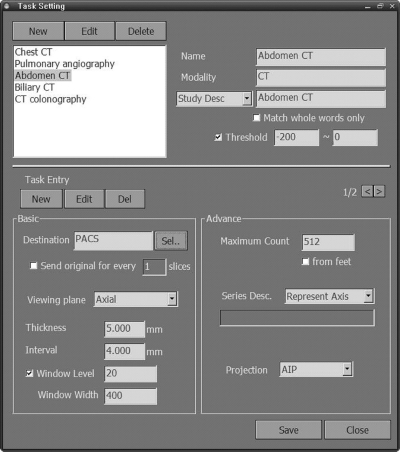
Adjustable reformation parameters include viewing plane (axial, coronal, sagittal, or oblique), slab thickness, interval between slabs, intensity projection algorithm (average, maximum, or minimum intensity projection), and window width/center. These reformation parameters can be defined differently for each study description. More than one parameter set can be defined per study description. The parameter sets for each study description are stored in a look-up table for fast access and users can easily browse and modify them using a graphical user interface (Fig. 1).
Fig 1.
Configuration of the reformation parameters. For a study with the Study Description Abdomen CT, a set of axial MPR images is generated with a 5-mm slab thickness, a 4-mm interval, an average intensity projection, a window width of 400, and a window center of 20.
Reconstruction Algorithm
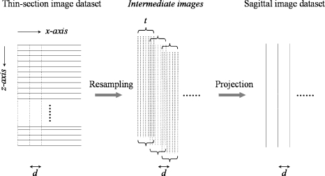
An MPR image is generated in two steps: resampling and projection (Fig. 2). In the first step, using thin-section source images, intermediate images parallel to a predefined viewing plane (eg sagittal) are resampled within a slab of predefined thickness, using a trilinear interpolation technique.12 The resampling interval is equal to the x- (or y-) pixel spacing of the thin-section source images so that the resampled intermediate images will have isotropic voxels. Finally, a slab MPR image is obtained by using the average, maximum, or minimum intensity projection of these intermediate images. The next MPR image is centered adjacent to the previous MPR image using a predefined parameter value, or interval between slabs, along an axis perpendicular to the viewing plane (eg x-axis in case of sagittal viewing plane). To the best of our knowledge, this algorithm for MPR is similar to those implemented in most CT scanner work station software.13
Fig 2.
Generation of sagittal reformation images. From thin-section source images (horizontal solid lines), intermediate sagittal images (vertical dotted lines) are resampled within a slab of a predefined thickness (t) using a trilinear interpolation technique. A sagittal slab MPR image (a vertical solid line) is then obtained by projecting these intermediate images. The next sagittal MPR image is centered adjacent to the previous MPR image according to a predefined interval between slabs (d), along the x-axis.
Triggering Mechanisms
To generate MPR images accurately and immediately, an effective triggering mechanism to initiate an automatic reformation is essential. If the reformation starts before all the thin-section images in a volume data set (series) arrive, the resulting MPR images would be truncated. If the reformation starts with a significant delay after all the images have arrived, the advantage of automation would be diluted. Because each individual image in a series being received does not contain any information about the data amount of the entire series (ie total number of images in the volume data set), it is challenging to detect the arrival of the entire series to initiate the reformation immediately.
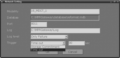
Multiplanar reformation Gateway uses two triggering mechanisms: DICOM Storage Commitment (DICOM standard, part 4) and time threshold, either of which can be chosen for each of the connected CT scanners (Fig. 3). When multiple series from a single or multiple studies are received simultaneously, the reformation for each series is triggered in sequence. The reformation proceeds for a complete volume data set (series) of images with the same series instance unique identifier (UID) (0020, 000E), while images of different series instance UIDs are received in a background manner and placed in a queue for sequential reformations. Users can reorder this reformation queue (Fig. 4).
Fig 3.
Configuration of the triggering mechanism.
Fig 4.
Dashboard.
DICOM Storage Commitment
For a received series, the reformation can be initiated by DICOM Storage Commitment, which is a DICOM service class to ensure that all images are successfully transmitted. After transmitting images of a volume data set (series) to the MPR Gateway, the CT scanner sends a list of the transmitted images to the MPR Gateway. If the MPR Gateway determines that all images were successfully stored, it sends a confirmation message back to the CT scanner, and then initiates the reformation from the received series. If the MPR Gateway determines that there are missing images, it sends a failure message and discards the received images.
Time Threshold
This mechanism is for CT scanners that do not support DICOM Storage Commitment for individual series. For a given series, the reformation is suspended for a specified threshold time (eg 90 s) after the last thin-section image has arrived. If no more images arrive during this period, the reformation is initiated.
DICOM Connectivity
The MPR Gateway serves as a DICOM Storage Service Class Provider when receiving thin-section image data sets from CT scanners and as a Service Class User when sending the result images to other DICOM stations. In addition, the MPR Gateway conforms to the Post-Processing Workflow Integration Profile in Integrating the Healthcare Enterprise Radiology Integration Profiles for the connection to imaging modalities, PACS, and Radiology Information System.
Test Results
A pilot system was tested in a hospital in which approximately 150 thin-section CT studies (mostly at 2-mm section thickness and 1-mm reconstruction interval) are performed daily with two 16- and one 64-detector-row CT scanners (Brilliance, Philips Medical Systems, Cleveland, OH, USA). Our institutional board approved this test and waived the informed consent. The system was implemented using C++ (Microsoft Visual C++, Microsoft Corporation, Redmond, WA, USA) and database (Microsoft DAO; Microsoft Corporation) on Microsoft Windows XP Professional (Microsoft Corporation). We installed this system in a server with a dual 3.06-GHz processor (Intel Xeon, Intel, Santa Clara, CA, USA) and a 4-GB main memory. The tested system and the 64-detector-row CT scanner were connected to the PACS servers through a gigabit network, and the two 16-detector-row CT scanners were connected to the PACS network through a 100-Mbps fast Ethernet connection. From thin-section data sets received from the three CT scanners, this system generated MPR images and sent them to the hospital PACS without failure for the 3-month test period. Once the network settings and reformation parameters were configured, the procedures of receiving, reformatting, and sending proceeded automatically and without any additional human operation.
To estimate the system speed, we measured the time to store reformatted images in PACS after the completion of the CT scan. The measurements were performed for 143 consecutive volume CT studies for 24 h on an average weekday. Each of these studies had 172–4,761 (mean ± SD, 932.6 ± 742.5) images divided into one to nine volume data sets (series). For each volume data set, two reformations were conducted: axial and coronal with 5-mm thicknesses and 4-mm intervals. The time to store a study in PACS ranged from 92 to 1,772 s (mean ± SD, 555.1 ± 509.4).
DISCUSSION
In this study, we propose an automatic system that generates MPR images on-the-fly according to predefined rules. Although a similar function is already available in a commercial CT scanner, to the best of our knowledge, our work is the first attempt to develop a system, which is independent of CT scanner type.
In generating MPR images from thin-section CT data sets, automation has several potential advantages over manual operation. First, patient throughput can be enhanced because CT technologists and scanners are freed from the simple repetitive task of generating MPR data sets and can concentrate on the scanning procedure. Such an exemption from manual tasks is not a trivial issue because data reconstruction and storage, together with patient management, are the most time-intensive steps in modern CT workflow, whereas CT data acquisition time is no longer a problem.14 Second, diverse CT imaging and archiving protocols can be managed more accurately and effectively.
There are several advantages of the proposed system over the common MPR solutions currently available in PACS packages and 3-dimensional visualization softwares. With the proposed system, MPR images of desired reformation parameters would be readily accessible as the axial sections are provided. This reduces the repetitive task of transmitting and loading immense data sets of source thin-section images to access MPR images. The proposed system would potentially decrease the need to keep the source CT images in online storage, which has been reported to account for 33% of the total image data in a filmless hospital.8
We did not formally analyze these potential advantages of our system by comparing its performance with those of manual operation or a similar automatic system built into commercial CT scanners. Because such research is affected by many extrinsic factors such as department policy, radiologists’ interpretation pattern, and CT work load as well as hospital network, it is difficult to draw a conclusion that can be generalized to many institutions. Nevertheless, we believe the proposed system can be helpful for streamlining the workflow in the management of ever-increasing CT data.
In spite of the aforementioned advantages, it is unlikely that our proposed system will completely replace manual MPR generations. In real clinical practice, there might be many instances when it is necessary to override predefined reformation rules. For example, a radiologist might want additional sagittal reformation images to depict a spinal lesion that was incidentally detected in an abdomen study. Radiologists might occasionally request oblique or double oblique images for complex anatomy, in which the fixed tilting angle is frequently inappropriate. Furthermore, with the increased computing power of reviewing workstations, radiologists will tend to prefer sliding slab viewing, which allows the navigation of volume data set with any desired slab thickness and viewing angle in an interactive real-time manner15–18 to reviewing MPR image data sets derived with fixed reformation parameters by our system.
CONCLUSION
We propose an automatic system that generates MPR images on-the-fly according to predefined rules, which is independent of CT scanner type.
Acknowledgments
This study was supported by Korea Health 21 R&D Project funded by Ministry of Health & Welfare, Republic of Korea (0405-VN06-0702-0001). We thank Tae Ki Kim, R.T. and Sang Tae Kim, R.T. for their technical assistance with the system integration.
References
- 1.Rubin GD. Data explosion: the challenge of multidetector-row CT. Eur J Radiol. 2000;36:74–80. doi: 10.1016/S0720-048X(00)00270-9. [DOI] [PubMed] [Google Scholar]
- 2.Tamm EP, Thompson S, Venable SL, McEnery K. Impact of multislice CT on PACS resources. J Digit Imaging. 2002;15(Suppl 1):96–101. doi: 10.1007/s10278-002-5004-2. [DOI] [PubMed] [Google Scholar]
- 3.McNitt-Gray MF. AAPM/RSNA physics tutorial for residents: topics in CT. Radiation dose in CT. Radiographics. 2002;22:1541–1553. doi: 10.1148/rg.226025128. [DOI] [PubMed] [Google Scholar]
- 4.Prokop M: Image processing and display techniques. In: Spiral and multislice computed tomography of the body. Stuttgart, Germany: Georg Tieme Verlag, 2003, pp 49–50
- 5.Cody DD. AAPM/RSNA physics tutorial for residents: topics in CT. Image processing in CT. Radiographics. 2002;22:1255–1268. doi: 10.1148/radiographics.22.5.g02se041255. [DOI] [PubMed] [Google Scholar]
- 6.Prokop M. Multislice CT: technical principles and future trends. Eur Radiol. 2003;13(Suppl 5):M3–13. doi: 10.1007/s00330-003-2178-z. [DOI] [PubMed] [Google Scholar]
- 7.Dalrymple NC, Prasad SR, Freckleton MW, Chintapalli KN. Informatics in radiology (infoRAD): introduction to the language of three-dimensional imaging with multidetector CT. Radiographics. 2005;25:1409–1428. doi: 10.1148/rg.255055044. [DOI] [PubMed] [Google Scholar]
- 8.Lee KH, Lee HJ, Kim JH, Kang HS, Lee KW, Hong H, Chin HJ, Ha KS. Managing the CT data explosion: initial experiences of archiving volumetric datasets in a mini-PACS. J Digit Imaging. 2005;18:188–195. doi: 10.1007/s10278-005-5163-z. [DOI] [PMC free article] [PubMed] [Google Scholar]
- 9.Paulson EK, Harris JP, Jaffe TA, Haugan PA, Nelson RC. Acute appendicitis: added diagnostic value of coronal reformations from isotropic voxels at multi-detector row CT. Radiology. 2005;235:879–885. doi: 10.1148/radiol.2353041231. [DOI] [PubMed] [Google Scholar]
- 10.Prokop M: Principles of CT, spiral CT, and multislice CT. In: Spiral and multislice computed tomography of the body. Stuttgart, Germany: Georg Tieme Verlag, 2003, pp 49–50
- 11.Rubin GD. 3-D imaging with MDCT. Eur J Radiol. 2003;45(Suppl 1):S37–S41. doi: 10.1016/S0720-048X(03)00035-4. [DOI] [PubMed] [Google Scholar]
- 12.Wolberg G: Image resampling. In: Digital image warping. Los Alamitos, CA: IEEE Computer Society Press, 1990, pp 117–161
- 13.Venema HW, Phoa SS, Mirck PG, Hulsmans FJ, Majoie CB, Verbeeten B., Jr. Petrosal bone: coronal reconstructions from axial spiral CT data obtained with 0.5-mm collimation can replace direct coronal sequential CT scans. Radiology. 1999;213:375–382. doi: 10.1148/radiology.213.2.r99nv11375. [DOI] [PubMed] [Google Scholar]
- 14.Roos JE, Desbiolles LM, Willmann JK, Weishaupt D, Marincek B, Hilfiker PR. Multidetector-row helical CT: analysis of time management and workflow. Eur Radiol. 2002;12:680–685. doi: 10.1007/s003300101138. [DOI] [PubMed] [Google Scholar]
- 15.Kim JK, Kim JH, Bae SJ, Cho KS. CT angiography for evaluation of living renal donors: comparison of four reconstruction methods. AJR Am J Roentgenol. 2004;183:471–477. doi: 10.2214/ajr.183.2.1830471. [DOI] [PubMed] [Google Scholar]
- 16.Napel S, Rubin GD, Jeffrey RB., Jr STS-MIP: a new reconstruction technique for CT of the chest. J Comput Assist Tomogr. 1993;17:832–838. doi: 10.1097/00004728-199309000-00033. [DOI] [PubMed] [Google Scholar]
- 17.Remy-Jardin M, Remy J, Artaud D, Deschildre F, Duhamel A. Diffuse infiltrative lung disease: clinical value of sliding-thin-slab maximum intensity projection CT scans in the detection of mild micronodular patterns. Radiology. 1996;200:333–339. doi: 10.1148/radiology.200.2.8685322. [DOI] [PubMed] [Google Scholar]
- 18.Lee KH, Kim YH, Hahn S, Lee KW, Kim TJ, Kang SB, Shin JH. Computed tomography diagnosis of acute appendicitis: advantages of reviewing thin-section datasets using sliding slab average intensity projection technique. Invest Radiol. 2006;41:579–585. doi: 10.1097/01.rli.0000221999.22095.b7. [DOI] [PubMed] [Google Scholar]


