Abstract
Consistent presentation of digital radiographic images at all locations within a medical center can help ensure a high level of patient care. Currently, liquid crystal displays (LCDs) are the electronic display technology of choice for viewing medical images. As the inherent luminance (and thereby perceived contrast) properties of different LCDs can vary substantially, calibration of the luminance response of these displays is required to ensure that observer perception of an image is consistent on all displays. The digital imaging and communication in medicine (DICOM) grayscale standard display function (GSDF) defines the luminance response of a display such that an observer’s perception of image contrast is consistent throughout the pixel value range of a displayed image. The main purpose of this work is to review the theoretical and practical aspects of calibration of LCDs to the GSDF. Included herein is a review of LCD technology, principles of calibration, and other practical aspects related to calibration and observer perception of images presented on LCDs. Both grayscale and color displays are considered, and the influence of ambient light on calibration and perception is discussed.
Key words: Medical imaging grade liquid crystal displays (LCDs), DICOM GSDF, observer perception, ambient light
INTRODUCTION
Consistent presentation of medical images is important to ensure a high level of patient care. Medical centers that were (or are) film-based ensured consistent image quality by distributing a single hard copy rendition of a radiographic examination to the various care providers. Given that the providers viewed the image on a light box of comparable luminance, all who viewed the image were provided the same rendition of that image. Medical practices and radiology departments are evolving to a digital rather than film-based image acquisition and distribution system. In many instances, this allows multiple providers in different locations to have simultaneous access to the images and provides the potential for better and more efficient patient care. Similar to a film-based practice, delivering a high-quality radiographic examination to all care providers helps ensure a consistent and high level of patient care.
Given that many newly acquired images are digital, there is a potential to view them on any number of computer systems. Computers as common as a standard personal computer (PC) or as sophisticated as a picture archival and communications system (PACS) work station may be used to view images. The need for consistent image presentation on this wide selection of work stations has been recognized1,2 as part of a broader description of a high-quality display, which is required for medical image presentation.3,4 For grayscale medical images, the Barten model of the human visual system’s response to contrast stimuli5 has been used to develop the digital imaging and communication in medicine (DICOM) grayscale standard display function (GSDF).6 The Standard provides a mathematical definition of the luminance output versus digital input which ensures perceptually equivalent contrast throughout the grayscale range of the display.
The purpose of this work is to provide an overview of DICOM grayscale calibration of medical imaging grade liquid crystal displays (LCDs). In the context of this work, a “medical imaging grade” display is a high-quality LCD, which is appropriate for medical image viewing. It has the general characteristics of minimal visual noise, an appropriately wide viewing angle range, minimal reflection of ambient light, and a grayscale luminance response that is calibrated to a known and accepted standard. Each of these display properties will be discussed, with greater detail and emphasis placed on grayscale calibration. Much of the information provided here has been presented previously by other authors and groups, and references to those works are provided. Successful calibration and use of LCDs in medical imaging requires an understanding of LCD technology. Therefore, a “Technology Overview” is provided. A combination of the GSDF and LCD technology provides the “Foundations of DICOM Calibration.” There are several “Practical Aspects of Calibration,” some of which will be discussed here. Grayscale calibration is evolving from inherently grayscale displays to grayscale calibration of color displays. The “Influence of Color” on the calibration of LCDs is underrepresented in the literature and will be discussed briefly. The light source of most LCDs is a combination of fluorescent lamps and light guides. Because the luminance output of the lamps changes over time, “Maintenance of Calibration” is required to ensure quality image presentation over time. Finally, there are several “Confounding Factors” to consider when calibrating and implementing medical imaging grade LCDs into clinical practice. These include the influence of viewing angle and ambient light. Whereas the influence of ambient light on the physical properties of a displayed image is well known, the influence of ambient light on the adaptation (and perception) of the human visual system is underrepresented in the medical imaging display literature and will be discussed briefly.
TECHNOLOGY OVERVIEW
Liquid Crystal Displays
Whereas the theory of grayscale calibration of medical imaging grade LCDs is based on the known response of the human visual system to contrast stimuli, practical calibration is implemented to both accommodate and utilize the specifics of LCD technology. A basic understanding of LCD technology is essential to appreciate the methods and limitations of calibration.
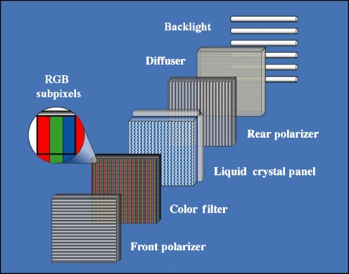
An active matrix liquid crystal display is often described as an optical “stack” containing a light source, light diffusers, polarizers, color filters (especially in case of a color LCD), and thin-film transistor liquid crystal matrix. An example of an optical stack is shown in Figure 1. The backlight is a combination of a light source and optical light guides and diffusers that serve to create a uniform luminance across the LCD surface. The light source is commonly a cold-cathode fluorescent lamp and may be implemented truly as backlights or commonly as “side” lights that are positioned along the outer edge(s) of the display. Other light sources, such as light emitting diodes or xenon lamps may also be used. The amount of light transmitted through the panel is a function of the relative orientation of the rear and front polarizers and the influence of the liquid crystal on the polarized light. The liquid crystal is a thin fluid layer of elongated organic molecules between glass plates. Linear “etching” of the inner surfaces of the glass plates preferentially orients the molecules near these surfaces parallel to the direction of the etching. In a resting state, the orientation of the molecules is determined by the direction of the etched grooves. As voltage is applied across the crystal, the molecules tend to preferentially align their direction in relation to the electric field. Orthogonal direction etching of the top and bottom surfaces of the liquid crystal layer provides an inherent “twist” in the orientation of the elongated molecules when a voltage is applied across the crystal. As the polarized light interacts with the twisted crystal, the plane of polarization tends to twist with the crystal. If the front and rear polarizers are oriented perpendicular to one another and the preferential plane of the polarized light is unaffected by the crystal, then very little light will be transmitted through the panel. If the molecules are highly aligned to the orthogonally oriented etching (caused by an applied voltage), then the polarized light is twisted 90° to align with the orientation of the front polarizer and a large fraction of light is transmitted. The applied voltage level influences to what extent the elongated molecules twist, thereby influencing the orientation of the plane of propagation of the once polarized light, which ultimately determines the amount of light that is transmitted by a small portion of the liquid crystal display. This description of LCD construction and operation is provided an as example. Details of the design and function of a specific LCD may well vary from the example provided there. However, the basic interactions between light, the polarizers, and the liquid crystal are common for all LCDs.
Fig 1.
Major components of an optical stack of a liquid crystal display. The color filters are omitted for inherently grayscale displays.
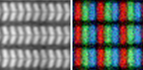
Each addressable LCD pixel has three subpixel elements, regardless of whether the display is inherently a color or a grayscale LCD. The three subelements correspond to the standard red, green, and blue color channels (RGB). In a color LCD, the colors are created by the addition of RGB filters. The color filters are omitted in inherently grayscale LCDs. Example color and grayscale pixel elements are shown in Figure 2. The “chevron” shape on the left in Figure 2 and the linear subpixels shown on the right are typical of many types of displays. As will be discussed later, the three subpixels will prove to be useful for grayscale calibration.
Fig 2.
3 × 3 pixel area of a grayscale (left) and color (right) LCD.
Grayscale calibration of LCDs is especially important because there is generally poor consistency in the inherent response of these displays. For example, the luminance (and perceived) contrast of an uncalibrated LCD can vary greatly throughout the input digital driving level (DDL) range of a single display.7 Also, because the inherent grayscale response of different LCDs can vary substantially, images presented on these different displays may appear quite different.
Light Measurement Devices
The intensity of light emitted by a display, or luminance, is typically specified to have units of candela per square meter (cd/m2). The relationship between cd/m2 and the older luminance unit foot-lamberts (fL) is given by 1 cd/m2 = 0.292 fL. Because LCDs are non-Lambertian surfaces, luminance is typically measured with a photometer, which has a narrow light acceptance angle (≤5°). Some photometers have a display to provide luminance measurements to the operator. Others interface with a computer, which can provide electronic data capture and display the luminance values. Often, medical imaging grade LCDs utilize a calibration software package that supports a limited number of photometers. For calibrating medical imaging grade displays, a photometer should be accurate to within 5% except for very low luminance levels (0.5 cd/m2) where an accuracy of 10% may suffice. The accuracy of any photometer used for calibrating medical imaging grade displays should be specified by the manufacturer. Note that photometers used for calibrating color LCDs have independent RGB measurement channels. This provides for calibration of the color tone as well as the luminance of color displays.
A photometer is an appropriate device to measure the luminance emitted (or reflected) from a display. Environmental lighting surrounding a display produces ambient light, or illuminance, which, by diffuse or specular reflection into the observer’s eye, may influence the physical contrast and the perceived contrast of a display. The typical unit of illuminance is the lux (lx). As opposed to the directionally oriented light emitted from a display, ambient light incident upon any object may come from any direction. Therefore, it cannot be measured directly with a standard narrow-angle photometer, but is rather measured using a photoreceptor behind an optical cosine diffuser. Whereas ambient light cannot be measured directly using a narrow-angle photometer, the ambient light reflected from a display can be measured with a narrow-angle photometer.
FOUNDATIONS OF DICOM CALIBRATION
The Barten Model
The goal of grayscale calibration of electronic displays is to ensure that images presented to an observer have equal perceived contrast appearance on all displays, independent of the luminance range of the display. To achieve this goal requires that, given a specific luminance scene, the contrast perceived by the human visual system (HVS) is well known. There are several experimental models of the perceived contrast of the human visual system. There are also multiple grayscale display function models, which have been and continue to be used to calibrate displays. These include the CIELAB display function (Commission Internationale de l’Eclariage), the log-luminance linear function,8 and the DICOM GSDF.7
The Barten model of the HVS5 was adopted by DICOM to define a standardized method of display calibration6 and is the only display function that will be considered further here. The Barten model was developed by measuring the sensitivity of the HVS to a low contrast, sinusoidal luminance signal (four cycles per degree subtending over 2°) presented on uniform luminance backgrounds. These experiments were conducted over a large luminance range (105). The luminance difference of the sinusoidal visual target from the background was varied to identify the luminance change, which rendered the target just barely visible. In this manner, a just noticeable difference (JND) was defined as the luminance change in the target that was required for the target to be perceived.
Experience has shown that the overall perceived contrast of an image presented on two GSDF calibrated LCDs of similar contrast ratio but different luminance ranges exhibit similar (although not exactly the same) overall contrast appearance. Another recognized limitation of the Barten model (and thereby the GSDF) is that, for a particular uniform background luminance, the luminance change required to perceive the visual targets was determined with the HVS adapted to that background luminance. In radiographic image viewing the HVS adapts to an overall scene luminance, but is required to perceive anatomical detail over the relatively wide luminance range of a displayed image. Because the HVS perception is optimized for a relatively narrow luminance range near the adaptation luminance, perception of detail in the light and dark portions of an image may be somewhat compromised.
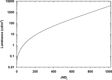
The DICOM grayscale standard display function describes a relationship between luminance and monitor input values such that the slope of the curve at any point, ie the contrast, is proportional (but not necessarily equal) to the contrast associated with a JND from the Barten model. The DICOM grayscale display function is often plotted graphically as luminance versus JND index (j), where the JND index values range from 0 to 1023. The DICOM grayscale display function is presented in Figure 3 this way. For a given luminance, the luminance change required to perceive a difference corresponds to a single JND. The model data have been fit to a polynomial, which provides a convenient mathematical transform to convert back and forth from units of luminance (cd/m2) to JNDj. The transform to convert from luminance (L) to JNDj6 (j) is provided in Eq. 1 and the transform to convert from JNDj to luminance2,4,6 is provided in Eq. 2. Alternatively, the luminance to JNDj transforms are available in tabular format.6
 |
1 |
A = 71.498068, B = 94.593053, C = 41.912053, D = 9.8247004, E = 0.28175407, F = −1.1878455, G = −0.18014349, H = 0.14710899, I = −0.017046845
 |
2 |
a = −1.3011877, c = 0.080242636, e = 0.13646699, g = −0.025468404, m = 0.001363533, b = −0.02584019, d = −0.10320229, f = 0.02874562, h = −0.003197898, k = 0.000129926
Fig 3.
DICOM Grayscale Standard Display Function plotted as the logarithm of the luminance as a function of JND index.
Theory of Calibration
To perform a DICOM calibration of a display, the desired postcalibration minimum (Lmin) and maximum (Lmax) luminance values are first identified. Because the luminance output of the backlights decreases over time, it may be reasonable to expect that the calibrated maximum luminance intensity selected may adversely affect the life expectancy of a display. The desired Lmax may be less than the maximum luminance that the device is capable of producing, Ldmax. Diagnostic monochrome monitors are now commonly calibrated for an Lmax of 400 to 600 cd/cm2, whereas color monitors used for clinical review will have an Lmax from 250 to 450 cd/cm2. Similarly, Lmin, corrected for ambient light effects, is often set to be larger than the black level of the display, Ldmin. The minimum possible Ldmin value is determined by the ability of an LCD to block the backlight.
The contrast ratio of a display is defined as
 |
3 |
Typical contrast ratios are in the range of 250 to 400 for color displays and up to 600 (or more) for inherently grayscale displays. Commonly, Lmin is specified to be slightly higher than the minimum possible value. This allows similar displays with different maximum luminance levels to be calibrated such that the luminance ratio Lmax/Lmin is the same and images appear with similar contrast.
After the Lmin and Lmax values have been specified, the corresponding JND index values (JNDmin and JNDmax) are determined using Eq. 1. The difference between JNDmax and JNDmin defines the total number of JNDs (JNDtot) that the calibrated display can produce. For example, a display with Lmin = 0.5 cd/m2 and Lmax = 200 cd/m2 has corresponding JNDmin = 46.6 and JNDmax = 572.2. In this example, JNDtot = 525.6. Most computers, video display driver cards, and displays are capable of 8-bit graphics. Regardless of whether the display is color or grayscale, an 8-bit grayscale palette is typical. Therefore, there are typically N = 256 grayscale digital driving levels available to a display system. The purpose of calibration is to set the luminance output for each input DDL such that throughout the entire DDL range, a change in DDL results in a JND index change that is constant. To accomplish this, the total number of JNDs is divided by the number of DDLs, minus one. This defines the average number of JNDs per DDL (JNDave) of the calibrated display. Continuing with the example started above, JNDave = 525.6 / 255 = 2.06. The JNDDDL of each DDL is next calculated as
 |
4 |
For each DDL, the luminance corresponding to each JNDDDL is then calculated using Eq. 2. Taken as a group, these values define the luminance display function of a DICOM calibrated display.
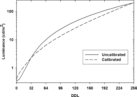
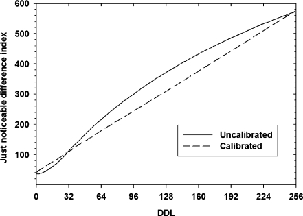
Just as the DICOM GSDF with JND indices is useful for calibrating displays, it is also useful for characterizing the contrast properties of both calibrated and uncalibrated displays. To characterize a display, luminance measurements can be converted to JND index values using Eq. 1. Example luminance and JND display functions are provided in Figures 4 and 5 for both an uncalibrated and a calibrated display. In Figures 4 and 5, note the lack of contrast for DDL values less than 8 and the relatively increased contrast for DDL values in the range 8 to 96 compared to the GSDF. For values greater than 128, the uncalibrated display has less contrast than the calibrated display. As might be expected, the JND space of a calibrated display is linear.
Fig 4.
Luminance as a function of digital driving level (DDL) for an uncalibrated display and a display that is calibrated to the DICOM Grayscale Standard Display Function.
Fig 5.
Just noticeable difference index value as a function of digital driving level (DDL) for an uncalibrated display and a display that is calibrated to the DICOM Grayscale Standard Display Function.
It is worth noting that calibrating displays to the GSDF with a similar luminance ratio can provide a similar image appearance on all displays, but this does not guarantee that the images necessarily look as desired. The overall appearance of digital medical images is dependent upon many variables including image acquisition parameters (peak kilovoltage [kVp] and mAs in x-ray, for example), image processing, and the various linear and nonlinear grayscale transforms provided for by DICOM Part 14.6 Provided that these variables are properly selected such that an image presents well on one GSDF display, it is reasonable to expect that the same image would present well on all GSDF displays. However, once a display is calibrated, ie its grayscale display function is set, any application-specific display function may be applied to the image data.
Eight-bit Palette Calibration
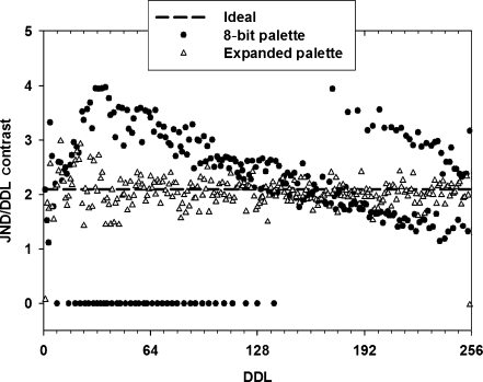
As shown in Figures 4 and 5, a luminance output that corresponds to the GSDF is not inherent to LCDs. Calibration requires creation of a look-up table (LUT) such that for each DDL, the LUT specifies a new DDL value that corresponds to a displayed luminance that matches (as closely as possible) that of an ideal DICOM display.9 A simple way to calibrate the overall luminance and contrast properties of a display is to create an 8-bit (256 values) LUT that converts an 8-bit input DDL value to the 8-bit output value which provides displayed luminance most similar to that defined by the GSDF. This scenario is generally considered to be an “8-bit-to-8-bit” transform. Figure 6 shows the JND/DDL contrast of an ideal GSDF calibrated display and a display that has been calibrated using an 8-bit LUT.
Fig 6.
JND/DDL contrast of the same display that was calibrated with an 8-bit grayscale palette and with an expanded (pseudo 10 bit) palette.
With the 8-bit-to-8-bit calibration, the net result is that the overall contrast of the display has the visual appearance of being calibrated. The overall perceptual contrast of the display is as desired. However, adjacent input pixel values may have output DDLs that are exactly the same, resulting in no displayed contrast between adjacent input levels. This effect is represented by the JND/DDL values in Figure 6, which have a value of zero. Also, adjacent input values may have output DDLs that differ by more than 1 (of 256) and the displayed contrast between adjacent input levels is excessive. This is also shown in Figure 6. Note that, for this example, the 8-bit-to-8-bit conversion resulted in 218 of a possible 256 unique gray levels in the calibrated grayscale function. The grayscale discontinuity caused by the 8-bit-to-8-bit LUT may result in “scalloping” or grayscale “banding” artifacts in a displayed image. Given that 8-bit-to-8-bit calibration generally results in loss of local contrast combined with excessive local contrast, it is generally not a satisfactory calibration method.
Expanded Palette Calibration
Calibration methods used for imaging grade displays recognize the limitations of the 8-bit-to-8-bit scenario outlined above.9 A common starting point for achieving a more precise calibration is to utilize the fact that each image subpixel can be independently addressed. Typically, the subpixels are set to an 8-bit value that varies by no more than 1 among the three. Used in this manner, independent addressing of the subpixels is referred to as bit stealing8 or spatial dithering.9 For monochrome monitors, a palette of 766 gray values may be obtained.11 For color monitors, a palette of 1,786 with imperceptible differences in color tone may be obtained.10,11
Use of an expanded grayscale palette, achieved by addressing the subpixels independently, provides the foundation for a more effective grayscale calibration. With the expanded palette, the output luminance can be made to more closely match the ideal luminance indicated by the GSDF. In contrast to the 8-bit palette, the same luminance value need not be used multiple times and the potential for very large and small contrast changes for adjacent DDLs is reduced. This results in a calibrated display, which more closely approximates that of an ideal display, as shown in Figure 6. Along with spatial dithering, the use of temporal modulation or temporal dithering of subpixels has been implemented by some manufacturers to further refine the luminance difference between LUT palette entries.9 Temporal dithering utilizes rapid temporal changes in the luminance output of individual subpixels to further refine the time-averaged luminance output. Temporal dithering occurs at a rate that is imperceptible to the human eye. Temporal dithering over four or eight frames results in 3,061 or 6,121 values in the grayscale palette.12
PRACTICAL ASPECTS OF CALIBRATION
Selection of Luminance Range
“Theory of Calibration” describes how a calibration LUT is derived once the desired Lmin and Lmax have been specified. For grayscale displays, typical calibrated Lmax values are in the range of 400 to 600 cd/m2. These displays generally have a contrast ratio of approximately 600:1. Therefore, Lmin could be specified as low as 0.66 to 1 cd/m2 to achieve a displayed luminance ratio equal to the device contrast ratio. Whereas the HVS can adapt to a large range of luminance levels, the luminance range of an adapted HVS is relatively limited.3,13 As a consequence, an image presented using a device with a luminance ratio of 600 results in very low perceived contrast in the dark regions. For this reason, it is preferable to calibrate a monitor such that the luminance ratio is in the range of 300 to 400. For example, a monochrome display calibrated for Lmax = 525 and Lmin = 1.5 will have a luminance ratio of 350. The Lmax of color displays is generally less than that of grayscale displays, and may range between 250 and 450 cd/m2. For the same luminance ratio, a color monitor thus has a lower Lmin, making them more susceptible to the adverse effects of ambient light.
It is important to note that GSDF calibration of different displays does not necessarily result in displays which are exactly perceptually matched. The GSDF ensures that the perceived contrast is consistent throughout the grayscale range of a given display, but calibrated displays that have substantially different maximum luminance values or contrast ratios will not provide an exact perceptual match. For example, a brighter display will still look brighter after calibration and a higher contrast display will still have higher contrast. Because the luminance and contrast properties of medical imaging grade LCDs is not widely variable, GSDF calibration of these displays will ensure that an image presented on each display will have a similar appearance.
Number of Luminance Sampling Points
It might be considered that calibration based on initial measurement of the luminance at every palette LUT value provides the best grayscale calibration. For cathode ray tube (CRT) displays, luminance output is well behaved with driving level and most calibration software coarsely sampled the palette and interpolated the intervening values. Therefore, the typical number of luminance measurement points used for CRT calibration is often in the range of 18 to 32. Note that American Association of Physicists in Medicine (AAPM) TG18 recommends measurement of 18 points along the grayscale range to assess GSDF conformance. Therefore, a display that was calibrated using measurements from the same 18 points would be expected to have a favorable TG18 luminance response evaluation.
For LCD displays, the luminance can vary discontinuously between adjacent palette LUT entries. Therefore, the number of calibration points should be much larger than the number of points used for CRT devices, and preferably equal to the full size of the grayscale palette. Similarly, calibration conformance should be checked for all 256 drive levels.
Assessing Calibration Quality
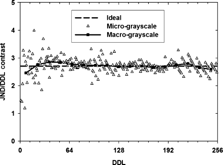
Postcalibration measurement of the grayscale response of a display can be used to assess the quality of the calibration. Detailed discussion of the methods used to assess calibrated display performance are available in the literature.4,11,14 Only a brief discussion and example are presented here. Typically, the luminance for a select number of DDL values is measured. The minimum and maximum DDL values should be used to verify appropriate calibrated Lmin and Lmax. A comprehensive assessment of display grayscale calibration involves measuring the luminance for each of the 256 DDL values. For a small sample of displays, this may be done using a quality photometer and manual recording of the data. Preferably, this can be done by using a photometer that interfaces directly to a computer. Characterization of calibrated displays via measurement of all 256 steps in the DDL range provides an overall assessment of the grayscale response. Both “macro-grayscale” (over a subset of DDLs) and “micro-grayscale” (between individual DDLs) can be assessed. Macroscale assessment may be performed by calculating the JND/DDL contrast between DDL values that are coarsely spaced. For example, the large scale conformance to the GSDF may be calculated using DDL values that are separated by 15. This is equivalent to the 18-step assessment recommended by the AAPM TG-18. Of course, assessment of the macro-grayscale conformance does not require measurement at all 256 DDL values. The additional value of measuring the luminance at each of the 256 DDL values is characterization of the micro-grayscale response. This is more important for LCD displays than for CRT displays. Discrepancy between the ideal GSDF and the actual micro-grayscale response can be considered an assessment of the contribution of an imperfect grayscale calibration to the noise of the displayed image.
Figure 7 shows the macro- and micro-grayscale response of a calibrated grayscale display. The macro-grayscale JND/DDL contrast measurement may be considered to be a local average of the micro-grayscale measurement. As shown in Figure 7, the macro-grayscale measurements do not provide a good indication of the precision of the micro-grayscale response. The TG-18 report and the DICOM GDFS recommend calculating the root mean squared error (RMSE) of the micro-grayscale JND/DDL contrast to characterize the calibration precision. It may be reasonable to calculate the normalized RMSE (nRMSE) by dividing by the average JND/DDL. The nRMSE provides a measurement of the relative noise, which may be useful for comparing displays with different average JND/DDL contrast values. The average JND/DDL contrast of the micro-grayscale JND/DDL contrast of Figure 7 was 2.7; the RMSE was 0.29; and the nRMSE was 0.11. Note that calibration noise should be considered in a relative comparison to other sources of noise in the medical image acquisition and display chain.15,16
Fig 7.
JND/DDL contrast of a DICOM GSDF calibrated grayscale display.
Storing the Calibration
There are many possible mechanisms to store and utilize calibration data. Only an introduction to these mechanisms is provided here. Depending upon implementation, the calibration look-up table may be stored on a host PC as an International Color Consortium (.icc) color profile (or similar). The computer operating system, in combination with the video card, can modify the DDL values sent to the display via the .icc profile. As a general rule, the .icc profile is available to both analog or digital visual interface (DVI) video output formats. The calibration data may also be stored in firmware of the LCD. In general, this type of implementation has the limitation that it can be applied only to a DVI input signal, but has the advantage that the calibration is immediately available if the display is moved to another PC with a DVI output channel. Certainly, other vendor-specific solutions to calibration storage and portability exist. Also, note that many imaging grade displays have other calibrated display function settings in addition to the GSDF setting (such as log-linear or CIELab), which are provided by the manufacturer and delivered as part of a new display.
INFLUENCE OF COLOR
Not surprisingly, grayscale calibration was originally performed on inherently grayscale displays. Grayscale calibration of color LCDs for medical image display is a relatively new practice. The implications of color on the grayscale calibration palette were discussed in “Expanded Palette Calibration”. Color displays have an inherent advantage for displaying radiographic images that contain color, such as nuclear medicine, Doppler ultrasound, and functional magnetic resonance images. Also, recent work has indicated that using color displays likely does not limit the ability of an expert observer to diagnose disease in chest radiographs.15 Given recent and continuing advances in the quality of color LCDs, it is reasonable to expect that the use of color LCDs for medical image viewing will continue to increase. Note that, as with grayscale displays, only high-quality color displays that are specifically tailored to medical image viewing should be used.
The construction of grayscale and color LCDs is similar, except that the color displays have red, green, and blue (RGB) color filters. Each of the color filters preferentially blocks a portion of the color spectrum contained in the “white” backlight source. Therefore, the maximum luminance output of color displays is considerably less than that of inherently grayscale displays. Although color displays are inherently dimmer than their grayscale counterparts, it is worth noting that there is currently an upward trend in the maximum luminance of color medical imaging grade LCDs.
All LCDs, including grayscale, have a color tone. The color tone of grayscale displays is a function of the fluorescent (or other) backlight and the transmission properties of the optical stack that may be included to adjust the color tone. For example, some grayscale displays have a blue hue similar to that of blue-base film. Contrary to what one might expect, identical models of grayscale displays may have noticeably different color tones. This is due primarily to variations in the manufacture of the backlights. The AAPM TG-18 report provides guidelines for establishing measurable color differences such that the color tone differences are not perceivable. The color tone of color displays can generally be specified during calibration. Therefore, it is reasonable to expect that no color difference should be perceived between similarly calibrated color displays.
MAINTENANCE OF CALIBRATION
Liquid crystal displays commonly use fluorescent lamps as the backlight source. The luminance output of the backlight is subject to change over time and therefore requires some sort of maintenance to ensure luminance stability. Most medical imaging grade displays have built-in backlight luminance sensors with feedback circuits to maintain the desired maximum luminance of the LCD based on proper calibration of the backlight sensor. Some of them also have sensors that measure the luminance output of a small area near the edge at the front of the display. The front of screen sensor has the potential to measure not only the maximum luminance, but can also be used to measure the luminance throughout the entire DDL range, albeit in a small area at the periphery of the display. The sensors in turn are calibrated with respect to the center of the LCD. That the front of screen sensor can measure luminance values throughout the entire DDL range can help to provide assurance that conformance to the GSDF is maintained over time. Whether an automated front of screen sensor is required to maintain conformance has not be established. Often, the sensor values are provided to administrative software that allows remote monitoring of the luminance properties as measured by back and/or front of screen sensors. Note that the luminance values obtained remotely are as reliable as the electronic sensors that measure them. Periodic, on-site evaluation of medical imaging grade LCDs is recommended to ensure overall display quality. Experience has shown that quarterly on-site evaluation is initially appropriate. It may be reasonable to modify the frequency of the on-site visits based on the frequency and severity of the problems found during these initial quarterly visits.
CONFOUNDING FACTORS
Viewing Angle
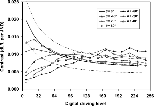
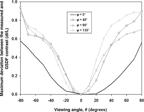
The luminance and contrast properties of LCDs are dependent upon the angle (with respect to the plane of the display face) from which the light photons are emitted and subsequently observed. Grayscale calibration of medical imaging grade LCDs assures conformance to the GSDF when a display is viewed from an angle perpendicular (or nearly so) to the display face. As has been recognized for some time, the changing optical properties of LCDs as a function of viewing angle can have a substantial influence on perceived contrast.14,17 Only a small area of an individual display can be viewed perpendicularly at any given time. When a standard 21-inch (53.3 cm) diagonal display is viewed on-center from a comfortable viewing distance of 70 cm, the viewing angle in the corners of the display is 20°. The influence of viewing angle can be measured using a CCD camera with either Fourier optics18,19 or wide-angle photographic lenses20 or through the use of a narrow-acceptance-angle photometer positioned at various angles with respect to the display face.14,18,21 Figure 8 shows an example of the change in the macro-grayscale conformance to the DICOM GSDF for various viewing angle deviations from perpendicular. In Figure 8, the data are plotted as the relative change in luminance contrast (dL/L) per DDL as a function of DDL. Notice that conformance to the standard starts to break down for relatively shallow viewing angle changes, where the viewing angle (θ) is the angular deviation from perpendicular and, for Figure 8, is specified along the horizontal axis of the display (φϕ = 0°). In Figure 9, note that the influence of viewing angle may vary for the long (ϕ = 90°) versus short axis (ϕ = 0°) of a display, or along diagonals (ϕ = 45°, 135°). The potential influence of viewing angle should be considered and accommodated during specification and installation, as well as routine use, of LCDs.
Fig 8.
Change in the luminance contrast of a 3MP grayscale display as measured at various angles (θ) along 45° angle (ϕ).
Fig 9.
Maximum deviation between the measured and GSDF luminance contrast measured as a function of viewing angle (θ) along the long axis (ϕ = 90°), short axis (ϕ = 0°) and diagonals (ϕ = 45°, 135°) of a display.
Ambient Light
The light emitted by a LCD as luminance can be considered to carry useful image information. In general, ambient light, which is incident upon a display face (including front-of-screen shields and filters) and reflected back toward an observer, has the potential to degrade the contrast properties of the image or otherwise affect an observer’s perception of that image. Reflected ambient light is a source of luminance coming from the display face and acts in addition to the luminance generated by the display. The optical properties of a display dictate the influence of ambient light. “Specularly” reflected light represents a mirror-like reflection with only minimal spatial or angular spread.4 “Diffusely” reflected light has a very broad spatial distribution, containing essentially no spatial detail.4 It can be demonstrated that the reflective properties of LCDs likely lies somewhere between specular and diffuse. For example, if one were to peer into a powered-off LCD in a well-lit room, one might expect to see the blurry outline of a person reflected back, but would likely not be able to distinguish facial features.
As an example, consider an LCD with Lmin = 0.5 cd/m2 (JNDmin = 47), Lmax = 200 cd/m2 (JNDmax = 572), and a coefficient of diffuse reflection of 0.005 cd m−2 lx−15. A typical office might have an illuminance of 200 lx15. In this case, the reflected ambient light results in an additional luminance of 1 cd/m2, with corresponding Lmin = 0.5 + 1.0 cd/m2 (JNDmin = 90) and Lmax = 200 + 1 cd/m2 (JNDmax = 573). The ambient light resulted in a loss of 42 JNDs (of an original 525) to the overall display function. If the display was calibrated assuming zero contribution from ambient light, then the JND (and perceived contrast) loss occurs in the low DDL, low-luminance portion of the display function. The calibration software for most medical imaging grade displays can account for the loss of contrast as a result of ambient light. If a display is recalibrated to accommodate additional luminance from reflected ambient light, then the JND loss is distributed equally throughout the entire DDL range.
In practice, it is useful to observe a monitor surface with the device turned off and with the observer located in a typical position. Any bright room lights that are visible as specular, or diffuse-specular, patterns indicate that the position of the work station in relation to the room lights needs to be changed. Additionally, when the device is turned on, the black regions of the display should be noticeable brighter than the surface luminance when the device is off. If not, it is an indication of excessive diffuse reflection that can be reduced be lowering the room lighting. This is easiest to observe with a pair of monitors.
Another aspect of ambient light is the influence that it has on the eye’s adaptation level. The adaptation level of the eye is dictated by the total luminance it receives. Much of this luminance comes from the scene on which an observer is immediately focused, but some of it also comes from other light sources in the periphery of the eye’s field of view. The influence of light sources peripheral to the focal point of the eye on the adaptation level has been described as disability glare.22–24 Disability glare is caused by imperfections in the optics of the eye, which scatters a fraction of the luminance outside the primary field of view onto the retina24 and is known to increase with age.23,24 Disability glare has been used to describe the influence of a point source of light on the eye’s adaptation. It may be reasonable to extend this model to include the light from all points in the periphery of the field of view. The influence of ambient light on the eye’s adaptation level and the perception of medical images is an area that would benefit from research.
At first, it might seem that the best way to deal with ambient light is to eliminate it. However, it is reasonable to expect that LCDs will continue to be used in clinical environments that require illumination for patient care. Further, it has been found that a modest amount of radiology reading room illumination (25–40 lx) is preferable to no illumination.25 In an earlier example, a JND loss of 42 was calculated for room illuminance of 200 cd/m2. If the ambient light is set to a perceptually comfortable illuminance of 25 cd/m2, then the JND loss would be a modest 7 JNDs. An understanding of the influence of ambient light on the contrast properties of a displayed image and on the adaptation and comfort levels of the HVS should be used to manage (not necessarily eliminate) ambient light in clinical care settings.
Display Visual Noise
“Assessing Calibration Quality” described how micro-grayscale measurements may be used to assess the contribution of display calibration to overall grayscale noise. The luminance measured with even a shallow angle photometer represents an average over many individual pixels. In this context, the micro-grayscale response was measured over a large (with respect to a single pixel) physical area. Smaller area variations in luminance result in spatial noise. That is, adjacent pixels addressed with the same DDL may have a different luminance output that contributes to an overall image noise. The spatial noise of LCDs has been described through precise measurement of the luminance of individual pixels21,26 and through measurement of the noise power spectrum.14–17,21,27Both of these methods of pixel noise measurement include the use of a high-quality CCD camera for photographic assessment. A method of minimizing the effects of pixel noise through the use of error diffusion has been proposed.26 Note that any measurement of the spatial noise of a display should be considered in context with the noise contributions of other parts of the image acquisition and display chain.15,27
SUMMARY
Consistent presentation of digital radiographic images is essential for ensuring a high level of patient care. To help achieve consistent image presentation, the DICOM Standard includes a Standard Grayscale Display Function derived from the Barten model of the human visual system. The theoretical principles used to calibrate displays are well known and straightforward. The methods used for calibration of medical imaging grade liquid crystal displays specifically account for and utilize LCD technology. Precalibration considerations include specification of the calibrated luminance range. The manner in which ambient light influences the physical and perceived contrast of a display, and how it may be accommodated, should also be considered. Because LCDs are non-Lambertian light emitters, the luminance output and contrast properties of LCDs are dependent upon the angle from which they are viewed. Therefore, the accuracy of grayscale calibration is variable with viewing angle. Whereas the influence of viewing angle cannot be accommodated through calibration, it should be considered when evaluating and implementing LCDs in the clinical practice. Color LCD technology is improving and it seems likely that their use will become more common both within and outside radiology reading rooms. Grayscale calibration of color displays is conceptually similar to that of inherently gray displays and allows calibration of multiple displays to a common color tone. For both gray and color LCDs, measurement of the micro-grayscale is required to ensure both the accuracy and precision of the calibration. It is important to note that grayscale calibration alone is insufficient to ensure an overall high level of displayed image quality. Whereas not specifically considered here, other aspects of display quality, including resolution and spatial noise, also have to be considered to ensure a high-quality, medical imaging grade display
References
- 1.Blume H, Roehrig H, Browne M, Lan Ji T. Comparison of the physical performance of high resolution CRT displays and films recorded by laser image printers and displayed on light-boxes and the need for a display standard. Medical Imaging IV: Image Capture and Display. SPIE. 1990;1232:97–114. doi: 10.1117/12.18846. [DOI] [Google Scholar]
- 2.Blume H. The ACR/NEMA proposal for a grey-scale display function standard. Image Display. SPIE. 1996;2707:344–360. doi: 10.1117/12.238462. [DOI] [Google Scholar]
- 3.Flynn MJ, Kanicki J, Badano A, Meyer WR. High-fidelity electronic display of digital radiographs. RadioGraphics. 1999;19:1653–1669. doi: 10.1148/radiographics.19.6.g99no081653. [DOI] [PubMed] [Google Scholar]
- 4.Samei E, Badano A, Chakraborty D, Compton K, Cornelius C, Corrigan K, Flynn MJ, Hemminger B, Hangiandreou N, Johnson J, Moxley M, Pavlicek W, Roehrig H, Rutz L, Shepard J, Uzenoff R, Wang J, Willis C. Assessment of Display Performance for Medical Imaging Systems, Report of the American Association of Physicists in Medicine (AAPM) Task Group 18. Madison, WI: Medical Physics Publishing, AAPM On-Line Report No. 03, April 2005
- 5.Barten PGJ. Contrast sensitivity of the human eye and its effects on image quality. Bellingham, WA: SPIE Press; 1999. [Google Scholar]
- 6.Digital Imaging and Communications in Medicine, Part 14: Grayscale Standard Display Function, published by National Electrical Manufacturer’s Association, 2001
- 7.Roehrig H, Chawla A, Krupinski E, Fan J, Gandhi K. Why should you calibrate your display? Penetrating Radiation Systems and Applications V. SPIE. 2003;5199:181–192. doi: 10.1117/12.515317. [DOI] [Google Scholar]
- 8.Ogawa E, Shimura K. Appearance matching of radiographic images using lightness index. Image Perception and Performance. SPIE. 1999;3663:324–332. doi: 10.1117/12.349656. [DOI] [Google Scholar]
- 9.Blume H, Ho AM, Stevens F, Steven PM. Practical aspects of grayscale calibration of display systems. PACS and Integrated Medical Information Systems: Design and Evaluation. SPIE. 2001;4323:28–41. doi: 10.1117/12.435509. [DOI] [Google Scholar]
- 10.Tyler CW, Chan H, Liu L, McBride B, Kontsevich L. How to get 1786 or more grey levels from an 8-bit color monitor. Human Vision, Visual Processing, and Digital Display III. SPIE. 1992;1666:351–364. doi: 10.1117/12.135981. [DOI] [Google Scholar]
- 11.Flynn M, Tchou P. Accurate measurement of monochrome luminance palettes for the calibration of medical LCD monitors. Visualization, Image-Guided Procedures, and Display. SPIE. 2003;5029:438–448. doi: 10.1117/12.480380. [DOI] [Google Scholar]
- 12.Courtesy of F. Stevens, Planar Systems, Inc., Waltham, MA, 2006
- 13.Hecht S, Hsia Y. Relation between visual acuity and illumination. J Gen Physiol. 1928;11:255–281. doi: 10.1085/jgp.11.3.255. [DOI] [PMC free article] [PubMed] [Google Scholar]
- 14.Blume H, Steven PM, Cobb M, Ho AM, Stevens F, Muller S, Roehrig H, Fans J. Characterization of high-resolution liquid-crystal displays for medical images. Visualization, Image-Guided Procedures, and Display. SPIE. 2002;4681:271–292. doi: 10.1117/12.466930. [DOI] [Google Scholar]
- 15.Langer S, Fetterly K, Mandrekar J, Harmsen S, Bartholmai B, Patton C, Bishop A, McCannel C. ROC Study of four LCD displays under typical medical center lighting conditions. J Digit Imaging. 2006;19:30–40. doi: 10.1007/s10278-005-8149-y. [DOI] [PMC free article] [PubMed] [Google Scholar]
- 16.Saunders RS, Samei E. Resolution and noise measurements of selected commercial medical displays. Med Phys. 2006;33(2):308–319. doi: 10.1118/1.2150777. [DOI] [PubMed] [Google Scholar]
- 17.Blume H, Steven PM, Ho AM, Stevens F, Abileah A, Robinson S, Roehrig H, Fan J, Chawla A, Ghandi K. Characterization of liquid-crystal displays for medical images—Part 2. Visualization, Image-Guided Procedures, and Display. SPIE. 2003;5029:449–473. doi: 10.1117/12.479774. [DOI] [Google Scholar]
- 18.Badano A, Flynn M, Martin S, Kanicki J. Angular dependence of the luminance and contrast in medical monochrome liquid crystal displays. Med Phys. 2003;30:2602–2613. doi: 10.1118/1.1606449. [DOI] [PubMed] [Google Scholar]
- 19.Samei E, Wright SL. Viewing angle performance of medical liquid crystal displays. Med Phys. 2006;33:645–654. doi: 10.1118/1.2168430. [DOI] [PubMed] [Google Scholar]
- 20.Fetterly K, Samei E. A photographic technique for assessing the viewing-angle performance of liquid-crystal displays. J Soc Inf Disp. 2006;14:867–872. doi: 10.1889/1.2372420. [DOI] [Google Scholar]
- 21.Badano A, Fifadara DH. Goniometric and conoscopic measurements of angular display contrast for one-, three-, five-, and nine-million-pixel medical liquid crystal displays. Med Phys. 2004;31:3452–3460. doi: 10.1118/1.1824198. [DOI] [PubMed] [Google Scholar]
- 22.Fisher AJ, Christie AW. A note on disability glare. Vision Res. 1965;5:565–571. doi: 10.1016/0042-6989(65)90089-1. [DOI] [PubMed] [Google Scholar]
- 23.Reading VM. Disability glare and age. Vision Res. 1968;8:207–214. doi: 10.1016/0042-6989(68)90007-2. [DOI] [PubMed] [Google Scholar]
- 24.Vos JJ. On the cause of disability glare and its dependence on glare angle, age and ocular pigmentation. Clin Exp Optom. 2003;86:363–370. doi: 10.1111/j.1444-0938.2003.tb03080.x. [DOI] [PubMed] [Google Scholar]
- 25.McEntee M, Brennan P, Evanoff M, Phillps P, Connor O, Manning WT. Optimum ambient lighting conditions for the viewing of softcopy radiological images. Image Perception, Observer Performance, and Technology Assessment. SPIE. 2006;6146:260–268. [Google Scholar]
- 26.Fan J, Roehrig H, Sundareshan MK, Dallas WJ, Krupinski E. Increasing contrast resolution and decreasing spatial noise for liquid crystal displays using digital dithering. Visualization, Display, and Image-Guided Procedures. SPIE. 2005;5744:251–262. doi: 10.1117/12.595901. [DOI] [Google Scholar]
- 27.Siegel E, Krupinski E, Samei E, Flynn MJ, Andriole K, Erickson B, Thomas J, Badano A, Seibert JA, Pisano E: Digital mammography image quality-image display. Journal of American College of Radiology (in press, 2006) [DOI] [PubMed]


