Abstract
Objective
To consider potential clinical needs, technical solutions and research promises of ultrahigh-field strength cardiovascular MR (CMR).
Methods
A literature review is given, surveying advantages and disadvantages of CMR at ultrahigh fields (UHF). Key concepts, emerging technologies, practical considerations and applications of UHF CMR are provided. Examples of UHF CMR imaging strategies and their added value are demonstrated, including the numerous unsolved problems. A concluding section explores future directions in UHF CMR.
Results
UHF CMR can be regarded as one of the most challenging MRI applications. Image quality achievable at UHF is not always exclusively defined by signal-to-noise considerations. Some of the inherent advantages of UHF MRI are offset by practical challenges. But UHF CMR can boast advantages over its kindred lower field counterparts by trading the traits of high magnetic fields for increased temporal and/or spatial resolution.
Conclusions
CMR at ultrahigh-field strengths is a powerful motivator, since speed and signal may be invested to overcome the fundamental constraints that continue to hamper traditional CMR. If practical challenges can be overcome, UHF CMR will help to open the door to new approaches for basic science and clinical research.
Keywords: Cardiovascular MRI, Ultrahigh-field imaging, Multiple transmit, MR technology, Parallel imaging
Introduction
The field of cardiovascular MRI (CMR) has evolved rapidly over the past decade, feeding new applications across a broad spectrum of clinical and research areas. The clinical need for speed and efficiency dictated by physiological motion and flow constraints has been a significant motivating force for the development of ever more rapid cardiovascular MR imaging techniques and advanced MR system hardware [1]. Today, a move towards widespread availability of high-field MR systems (B0=3.0 T) is underway [2–4]. Another development that is looming on the CMR research horizon is the move towards ultrahigh-field, whole body MR systems (B0≥ 7.0 T) [5–10]. The gains in signal-to-noise ratio (SNR), contrast-to-noise ratio (CNR), imaging speed and efficiency associated with increases in field strength promise not only to improve and streamline structural and functional imaging, but also to facilitate targeted tissue characterization through molecular imaging and parametric mapping, and thereby to improve access to (patho)physiological processes and mechanisms.
Such improvements would benefit an ever-growing set of indications for CMR, including the detection and differentiation of ischemic and inflammatory disorders [11]. CMR has the unique potential to differentiate prospectively between reversible and irreversible myocardial injuries [12], and to detect small regions of myocardial fibrosis [13] or inflammation [14–18]. Quantification of MR signal changes enables monitoring of disease processes on a tissue level, which has clinical implications for the non-invasive workup of inflammatory disease [19]. From the clinical point of view, an early and robust detection of myocardial injury could enable tailoring of therapeutic strategies to prevent or delay disease progression. For other disease processes, CMR has as of yet untapped potential. Left ventricular (LV) dysfunction is an important early indicator of many cardiac diseases including coronary artery disease, congestive heart failure, hypertrophic cardiomyopathy, valvular heart disease, diabetes mellitus and hypertension. Whereas in diseases with impaired systolic function the diagnostic criteria are well known, CMR detection of diastolic dysfunction remains an unmet clinical need because of current deficits in the temporal resolution of MRI. Also, the non-invasive assessment of perfusion defects is of paramount clinical interest, e.g., to address the unsolved problem of differentiating significant sub-epicardial stenosis from microvasculature changes. It is well known that in several diseases like arterial hypertension and diabetes mellitus, the detectable myocardial ischemia is not induced by significant stenosis of the large vessels. Quantitative approaches including emerging technologies such as blood oxygen level-dependent T2*-mapping may help to overcome that hurdle and hence may offer the opportunity to eventually reduce the number of non-therapeutic cardiac catheterizations. For all these reasons, it is appealing to pursue the development and clinical implementation of ultrahigh-field CMR applications.
Unfortunately, the image quality achievable at ultrahigh fields is not always exclusively defined by SNR considerations. For example, in current practice, some of the inherent advantages of ultrahigh-field MRI are offset by the simple practical challenge of synchronization of data acquisition with the cardiac cycle using conventional ECG. Other practical impediments are associated with magnetic field inhomogeneities, off-resonance artifacts, dielectric effects and RF non-uniformities, localized tissue heating and RF power deposition constraints. All of these effects can undermine the benefits of ultrahigh-field strengths, in many cases making it a challenge even to match the image quality of CMR at 1.5 T. Still, the promise of increased spatial-temporal resolution afforded by ultrahigh-field strength is a powerful motivator, since speed and signal may both be invested to overcome the fundamental constraints that continue to hamper some of the low-field CMR applications. If practical challenges can be overcome, ultrahigh-field CMR will open the door to new approaches for both basic science and clinical research.
In the sections that follow, examples of ultrahigh-field CMR imaging strategies and their clinical value are provided. Unsolved problems and unmet needs are also considered carefully in an attempt to stimulate the imaging community to throw further weight behind the solution of these issues. First, key concepts, technical solutions and practical considerations for CMR at 7 T are outlined. Current trends—such as the trend towards multiple transmit architecture—are surveyed. A concluding section explores future directions. Of course, ultrahigh-field CMR is an area of vigorous ongoing research, and many potentially valuable developments will receive only brief mention here.
Key concepts and technical solutions for CMR at 7 T
Parallel transmit architecture
The requirements of CMR at 7 T are a strong driving force for further advances in RF coil technology and MR system architecture. As a deep-lying organ surrounded by inhomogeneous tissue structures within the comparatively large volume of the thorax, the heart is particularly susceptible to wavelength-related RF field focusing and distortion effects that accompany ultrahigh magnetic field strengths. One recent development that can counteract or harness these effects is the extension of the parallel receive concept to the realm of RF transmission. Parallel excitation approaches [20, 21] using arrays of independent RF synthesizers and transmit coil elements have been shown to allow exquisite control over the electromagnetic fields by modulating amplitude, phase and frequency used for excitation of the MR signal of each transmit channel independently. Early versions of parallel transmit systems were constructed either by using custom equipment or by integrating multiple sets of commercial MR system electronics [20–23]. Commercial systems with two integrated transmit channels have since appeared, and continued development may be expected.
The multiple transmit approach, taking advantage of interferences between distinct transmit elements, may be used to mitigate field-strength-related constraints such as (1) exacerbated conductive and dielectric effects in tissue that manifest as local/regional signal inhomogeneities resulting from B1 non-uniformities or even signal voids, and (2) increased and locally focused RF power deposition (quantified as specific absorption ratio, or SAR) that can cause local tissue heating. There is a fundamental tradeoff between correction of signal inhomogeneities and reduction of SAR, with improvements in one necessitating degradations in the other; however, the degrees of freedom inherent in parallel transmission have been shown to allow the design of simultaneously SAR-reduced and high-fidelity RF excitation pulses, thereby improving management of the tradeoff [24].
The degrees of freedom associated with distinct RF excitation waveforms may also be used, in close analogy to parallel reception, as a means of accelerating complex RF pulses—a concept termed transmit parallel imaging or transmit SENSE [23]. Another fundamental tradeoff—between excitation pattern complexity and RF pulse duration—may also, therefore, be managed effectively with parallel excitation. For example, parallel transmit techniques have been productively employed for spatially selective excitation of arbitrary target patterns [25]. Potential applications include targeted or curved excitation and zoomed imaging using an FOV smaller than the object size [26]. Zoomed imaging with tailored parallel transmit pulses can be accomplished without the risk of aliasing artifacts since magnetization is only excited in the target area, which has tremendous practical implications for future cardiac imaging applications.
Other applications of parallel transmit MRI take an approach that has been called B1+ shimming [27, 28], which improves the homogeneity of the transmit component of the RF magnetic field. B1+ shimming is a special case of fully parallel transmission in which the driving amplitude and phase, rather than the full time-dependent RF waveform—are adjusted at multiple transmit ports or coils in order to tailor excitation patterns. B1+ shimming has typically been used to reduce RF non-uniformities, to maximize B1+ coherence and to enhance the excitation efficiency as well as SNR and tissue contrast for target locations in the body. In the period of early development of B1+ mapping and B1+ shimming techniques and in the explosion of alternative approaches that followed, neurovascular and cardiovascular implementations abounded. For example, Fig. 1 shows a four-chamber view of the heart acquired at 7.0 T using a 4-channel cardiac customized transmit/receive coil with and without B1+ optimization. Images acquired without B1+ shimming (Fig. 1a), i.e., same transmitter amplitude, phase and frequency for each of the four transmit channel display RF inhomogeneity-related signal voids in the myocardium or blood pool. In comparison, B1+ shimming (Fig. 1b) using specific settings in transmitter amplitude, phase and frequency for each individual transmitter produces images with markedly enhanced signal homogeneity. Simulations predicted that further improvements in B1+ homogeneity can be achieved by increasing the number of transmit coil elements, for example, by moving from four to eight elements.
Fig. 1.
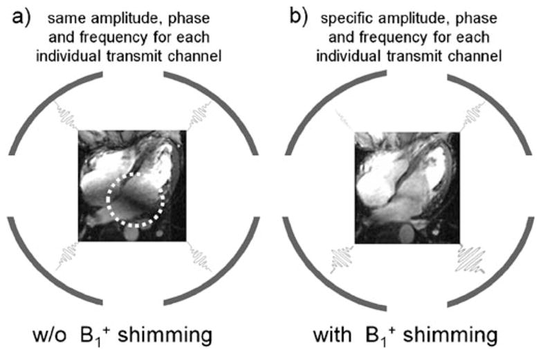
Long-axis, four-chamber views of the heart obtained at 7.0 T using 2D CINE FLASH imaging and a 4-element transmit/receive RF coil array without (a) and with (b) B1+ shimming. The image acquired without B1+shimming shows significant B1+ inhomogeneities resulting in severe signal voids marked by the dashed circle. B1+ shimming significantly improves signal uniformity across the target area
Transmit/receive cardiac coil arrays
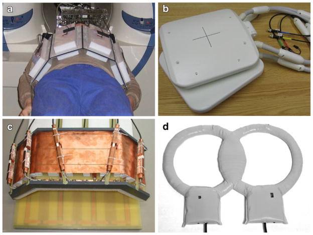
The RF inhomogeneities in large body regions such as the thorax are generally so significant, in fact, that traditional birdcage body coils are no longer used for signal excitation at 7 T, and large volume body coils are not even provided with commercial 7.0-T scanners. Transmit-receive (TX/RX) structures are therefore not a nicety, but a necessity for ultrahigh-field CMR. In RF coil array configurations customized for CMR, the coil elements located on the chest wall and towards the left side are of chief importance due to the heart’s position in the chest cavity. The use of comparatively small, deep-lying fields of view with multiple subject-specific oblique image plane orientations, together with considerations of patient comfort and the need to control RF energy deposition in tissue, presents a challenge for the design of transceive cardiac coil arrays. While it is possible to combine single-element transmit designs with multi-element receive arrays, the use of transmit-receive arrays with the capability for RF shimming or fully parallel transmission is prudent for the attainment of routine clinically acceptable image quality. Recent prototypes for 7.0-T transceive torso coil arrays used for CMR have typically been laid out as strip line elements on rigid or semi-flexible frames. In one leading-edge design, each element in a so-called transverse electromagnetic (TEM) transceiver array was connected to a dedicated RF power amplifier with independent phase and magnitude control, a transmit/receive switch and a preamplifier for reception [5]. Other versions of cardiac-optimized 7.0-T transceiver arrays have used flexible designs consisting of a pair of four-element strip line arrays, one placed anterior and the other posterior to the torso [6, 29], with element spacing carefully selected for decoupling as shown in Fig. 2a. A subsequent cardiac-optimized 7.0-T transmit-receive configuration has used loop elements rather than strip lines. This four-element design has two rectangular loops, each with a loop size of 13×20 cm2 mounted on an anterior former, and two similar rectangular loops on a posterior former, curved to conform to an average torso as illustrated in Fig. 2b [30]. The coil elements were overlapped for the purpose of nearest neighbor decoupling, with further decoupling accomplished with a common conductor shared by pairs of loops, together with a decoupling capacitor. Recently, an 8-channel TX/RX cardiac/body coil design was proposed [31], which comprises five angled loops for the anterior and three planar loops for the posterior part, as demonstrated in Fig. 2c.
Fig. 2.
Experimental versions and prototypes of cardiac optimized 7.0-T transceiver coils including (a) a flexible design consisting of a pair of four-element strip line arrays, one placed anterior and the other posterior to the torso [29], (b) a transmit-receive configuration that uses loop elements rather than strip lines [30], (c) an 8-channel TX/RX coil design [31], which comprises five angled anterior plus three planar posterior loops and (d) a quadrature coil [9]
Since sophisticated multi-transmit MR systems are not widely available yet, comparatively simple coils have also been used, with an effort to optimize the design for cardiac imaging. One example shown in Fig. 2d is a simple quadrature coil for cardiac imaging at 7 T [9], with a design tailored to produce B1+ fields with no tissue-induced signal voids within the heart. Using this setup, morphological, functional cardiac imaging plus coronary artery imaging has been performed successfully, though the limited depth penetration remains a concern for patients with a large body mass index.
Further developments are expected in array design for CMR at 7 T. Though the broad spectrum of CMR applications makes it challenging to identify a single optimal many-element transceive coil array design, the selected design should meet the following minimum requirements: (1) light weight; (2) capable of accommodating multiple patient positions, body habitus and anatomical variants; (3) ease of clinical use; (4) sensitive region large enough to cover the cardiovascular anatomy of choice (for example, heart+pulmonary vessels); (5) for the case of parallel reception, a desirable noise amplification profile for image planes of interest, and for parallel transmission and reception, a multidimensional arrangement of coil elements to enable multidimensional accelerations and patient comfort.
While much of the work on transmit-receive array structures for CMR is currently occurring at 7.0 T, recognition of the benefits of these structures may result in an eventual migration to 3.0 T, where the RF inhomogeneity effects for CMR, though somewhat reduced, remain significant.
Novel cardiac gating and triggering technology
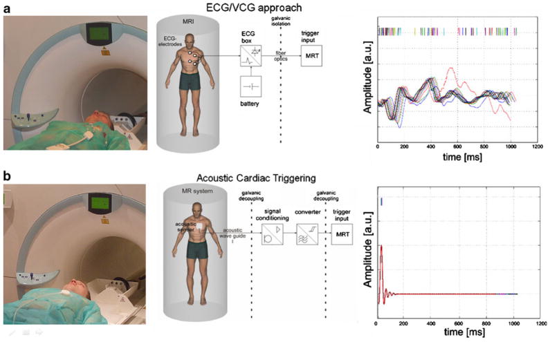
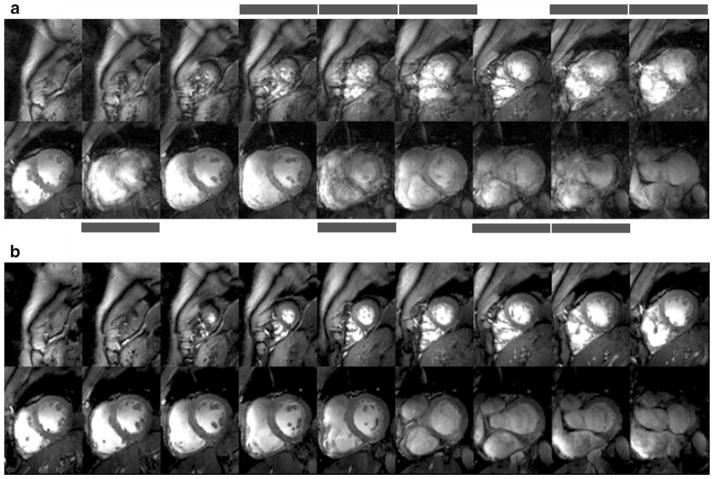
As ultrahigh-field cardiac MRI becomes more widespread, the significance of artifact sensitivity of ECG recordings increases and with it the motivation for a practical gating/triggering alternative. Since ECG is an inherently electrical measurement with electrically active components [32], it does carry a risk of surface heating of patients’ skin and even of severe skin burns resulting from induction of high voltages in ECG hardware [33–37]. ECG and even advanced vector-cardiogram (VCG, [38]) approaches are corrupted by interference from electromagnetic fields and by magneto-hydrodynamic effects that increase with increasing magnetic field strengths [39]. Consequently, artifacts in the ECG/VCG trace and T-wave elevation might be misinterpreted as R-waves resulting in erroneous triggering together with motion-corrupted image quality, an issue that is pronounced at ultrahigh fields. For all of these reasons, a non-invasive acoustic cardiac triggering (ACT) approach (which may also be termed “MR stethoscopy”) was recently proposed in the pursuit of reliable cardiac gating [40], as illustrated schematically in Fig. 3. ACT does not require any hardware or software changes on the scanner side and ensures full compliance with safety regulations for medical devices. The MR stethoscope presents no risk of high voltage induction and patient burns, is suitable for a broad range of magnetic field strengths, and provides patient comfort, ease of clinical use, insensitivity to electromagnetic fields and high trigger reliability. Acoustic cardiac gating was found to meet the demands of CMR applications at 1.5 T, 3.0 T and 7.0 T, including breath-hold and free-breathing acquisition strategies together with prospective and retrospective triggering regimes [7, 41]. For example, the MR stethoscope provided phonocardiograms at 7.0 T free of interferences from electromagnetic fields or magneto-hydrodynamic effects, as shown in Fig. 3b. Frequent R-wave mis-registration has been reported for ECG triggered CMR at 7.0 T [42, 43], which manifests itself in a severe jitter of R-wave recognition tickmarks as demonstrated in Fig. 3a. Consequently, 25% of the subjects needed to be excluded from left ventricular function assessment because of ECG-triggering issues in 2D CINE imaging at 7.0 T [43]. Acoustically triggered CINE imaging at 7.0 T produced images free of motion artifacts for all slices as shown in Fig. 4b. In contrast, ECG-triggered CINE imaging was prone to severe cardiac motion artifacts if R-wave misregistration occurred as illustrated in Fig. 4a. In this example of erroneous ECG triggering, cardiac motion induced blurring in 9 out of 18 slices. Practically speaking, this corresponds to an ECG failure rate of up to 50%.
Fig. 3.
Clinical setup (left), block diagram (center) and physiological waveforms (right) for (a) conventional ECG gating and (b) acoustic cardiac triggering (ACT) for synchronization of MR imaging with the cardiac cycle. Signal traces were recorded simultaneously with ECG and ACT sensors located in the isocenter of a 7.0-T magnet. Interference by electromagnetic fields and magneto-hydrodynamic effects cause severe distortion in the vector ECG waveform acquired during free breathing, resulting in erroneous trigger recognition, which manifests itself in a severe jitter in the R-wave recognition. In comparison, ACT is free of interferences from electromagnetic fields and magneto-hydrodynamic effects, and provides a reliable trigger signal free of jitter even in the presence of free breathing. Note that neither the limited ECG in the MR scanner nor the acoustic waveforms shown here should be treated as reliable indicators of patient emergency conditions
Fig. 4.
Short-axis diastolic views obtained from breath-held apex-to-base 2D CINE FLASH acquisitions (slice thickness=4 mm) using (a) vector ECG and (b) ACT gating. Vector ECG triggered 2D CINE FLASH imaging was prone to severe cardiac motion artifacts if R-wave mis-registration occurred. Images suffering from cardiac motion-induced blurring are marked with bars. Acoustic gating provided high-quality images free of cardiac motion effects for all slices
Practical considerations and early applications of CMR at 7 T
MR safety
CMR at 7.0 T falls into the controlled operating mode category of static magnetic field limits recommended by the International Commission on Non-Ionizing Radiation Protection (ICNIRP) [44]. At 7.0 T there is a need to ensure that subjects are moved slowly into the magnet bore to avoid the possibility of vertigo and nausea [44]. Thresholds for motion-induced vertigo have been estimated to be around 1 Ts−1 for greater than 1 s [44]. Avoiding these sensations is likely to afford protection against other effects of induced electric fields and currents that arise as a consequence of motion in a static magnetic field [44]. For all these reasons, patient table motion is recommended to be lower than 1 Ts−1. Hence, it is recommended to set table motion to be inversely proportional to the gradient in the magnetic field strength. The MR safety assessment of implants, intracoronary stents and other implantable medical devices at 7.0 T is at a very early stage of exploration. Consequently, it is too early to make ultimate statements, so that implants, intracoronary stents, pace makers, mitral and aortic valve replacements, cochlear implants, insulin pumps, neuro-stimulators and other implantable medical devices are currently considered to be contraindications for CMR at 7.0 T, unless otherwise certified or approved for 7.0 T.
Assessment of global cardiac function and myocardial wall motion
Dynamic CINE imaging of the heart is of clinical relevance for the assessment of cardiac morphology, myocardial contractile function and wall motion. Since the late 1990s, steady-state free precession (SSFP) techniques have been known to provide a consistently high SNR and high native contrast between myocardium and the ventricular cavity throughout the cardiac cycle. SSFP CINE imaging is a clinical workhorse at 1.5 T. Two-dimensional CINE SSFP imaging at 7.0 T remains elusive because of RF power deposition constraints and due to pronounced banding artifacts. Here, the use of spoiled gradient echo CINE imaging presents a valuable alternative. A recent report demonstrated that cardiac chamber quantification at 7 T using 2D CINE FGRE is feasible and agrees closely with LV parameter derived from 2D CINE SSFP imaging at 1.5 T [45]. In detail, no significant difference was found for ejection fraction and cardiac volumes between SSFP at 1.5 T and FGRE at 7.0 T. Cardiac mass derived from FGRE at 7.0 T using a slice thickness of 7 mm, which is commonly used in current clinical practice, was slightly larger than that obtained from SSFP at 1.5 T. Agreement of cardiac mass obtained from SSFP at 1.5 T and FGRE at 7.0 T was improved when using a slice thickness of 4 mm at 7.0 T.
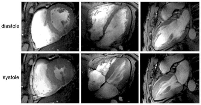
At 7.0 T, prolongation of the T1 of blood and myocardium manifests itself in an improved contrast between myocardium and blood that is superior to that obtained for gradient echo imaging at 1.5 T. Unlike 1.5-T acquisitions, this contrast exists not only for short-axis views of the heart placed perpendicular to the blood flow, but may also be observed for long-axis views parallel to the blood flow, as demonstrated in Fig. 5. Consequently, fine, subtle anatomic structures, such as the pericardium, mitral and tricuspid valves and their associated papillary muscles, and trabeculae are identifiable. In another example shown in Fig. 6, the baseline SNR gain at 7.0 T was translated into a reduction of the slice thickness, which was set to values as low as 2.5 mm, while accomplishing a 1 mm2 in-plane spatial resolution. This helps to reduce partial volume effects, which may be particularly useful for visualizing small, rapidly moving structures such as valve cusps, assessing subtle anatomical features such as trabeculae or extending morphologic assessment to the right ventricle.
Fig. 5.
2D FLASH CINE images acquired at diastole (top) and systole (bottom) using a 4-channel transmit/receive RF coil array at 7.0 T. Slice locations representing a mid-cavity short-axis view (left), four-chamber view (center) and two-chamber view (right) are shown
Fig. 6.
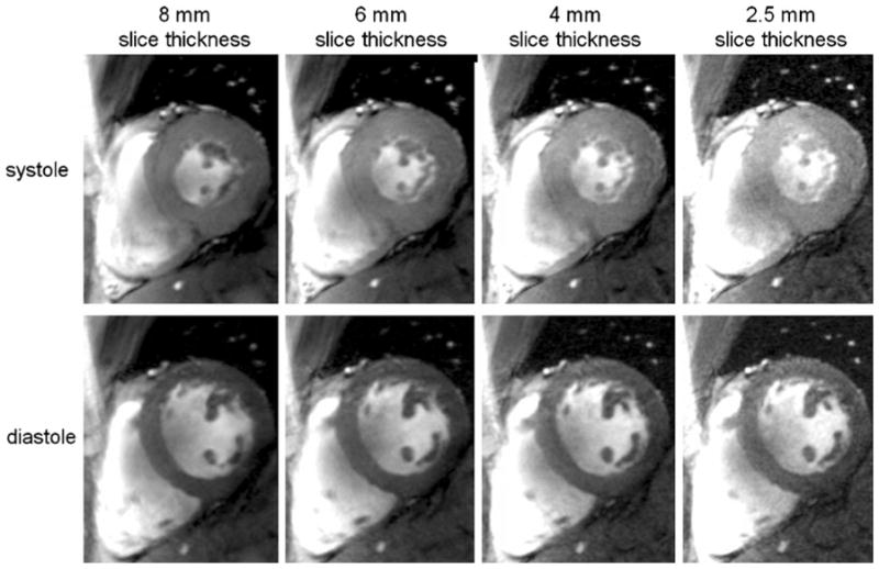
Mid-cavity short axis views acquired with 2D FLASH CINE at systole (top) and diastole (bottom) using a 4-channel transmit/receive RF coil at 7.0 T. The baseline SNR advantage at 7.0 T was translated into a reduction of the slice thickness from 8 mm (left) to 2.5 mm (right), while achieving (1 × 1) mm2 in-plane spatial resolution
Magnetic resonance angiography
Phase-contrast MRA at ultrahigh fields promises to tolerate larger deviations from the ideal encoding velocity, especially in the case of slow flow, due to the reduced phase noise level [3]. The SNR increase depicted in Fig. 7 for magnitude images obtained at 7.0 T vs. 1.5 T is accompanied by an increase in the velocity-to-noise ratio. Further in vivo studies are required to compare quantitative flow measurements at ultrahigh fields with measurements at 1.5 T and 3.0 T, and to extend such approaches to small vessels such as coronary arteries. In this context, another intriguing and rapidly advancing area of high-field CMR is time-resolved 3D imaging of flow connectivity together with the generation of particle trace maps [46]. This approach promises to provide new insights into temporal and spatial evolution of flow in large vessels and in the cardiac chambers. The benefits of such improvements would be legion, including improved morphological and functional assessment of the normal or diseased cardiovascular system. The SNR advantages of ultrahigh-field imaging, moreover, raise the prospect of extending existing 4D phase contrast strategies to whole-heart acquisitions.
Fig. 7.
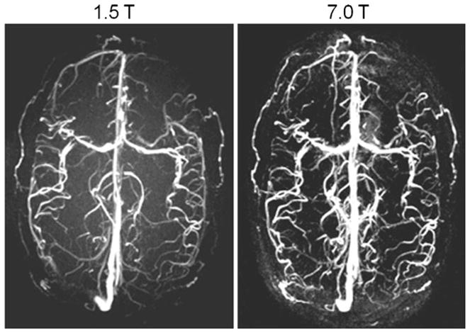
Axial 3D phase contrast MR angiograms of the brain derived from a healthy subject at 1.5 T (left) and 7.0 T (right) using acoustic cardiac gating. A significant SNR increase can be appreciated at 7.0 T vs. 1.5 T
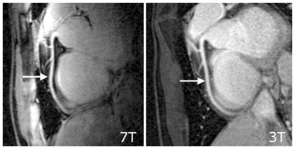
Very preliminary results obtained at 7.0 T [8] suggest that the use of ultrahigh-field strengths in conjunction with pulse sequences optimized for 7.0 T and tailored RF coil array designs may enable coronary MR angiography (cMRA) [47]. Despite the baseline SNR improvement at 7.0 T, the issue of off-resonance sensitivity of SSFP-techniques remains a severe concern at 7.0 T, which has prompted a return to gradient-echo imaging techniques in coronary artery imaging. Using a quadrature transmit/receive coil at 7.0 T together with a gradient echo imaging technique, it has very recently been shown that 7.0-T coronary MRA image quality may already begin to approach that at 3.0 T (Fig. 8) at this early stage of the development process [47]. In this pilot study, vessel sharpness at 7.0 T was found to be improved compared to that at 3.0 T.
Fig. 8.
Comparison of right coronary artery images derived from the same subject at (left) 7.0 T and (right) 3.0 T [47]. Gradient echo imaging (TR/TE/FA 4.3 ms/1.38 ms/15°, data matrix 512×312) using a spatial resolution of (0.82×0.82×2) mm3 was performed. For signal transmission and reception, a local quadrature coil was used at 7.0 T. A large-volume body coil was used for excitation at 3.0 T in conjunction with a six-element cardiac optimized receive array. At this early stage of the development, this study shows that 7.0-T RCA images can already be acquired with image quality comparable to those using much more sophisticated many element RF coil receive arrays at 3 T
Perhaps UHF MR forms another important enabling factor to transform the baseline SNR advantage into improved spatiotemporal resolution of contrast-enhanced MR angiography (MRA). Here, research continues to examine the impact of prolonged T1 relaxation times and altered R1 relaxivity of clinically approved gadolinium(III) chelate-based contrast media [48] on the blood/background tissue contrast at 7.0 T.
Parametric mapping and tissue characterization
Ultrahigh-field MR techniques are also in the spotlight for quantitative CMR applications that aim at parametric mapping for non-invasive tissue characterization. For example, blood may be used as an endogenous marker together with susceptibility-weighted imaging or quantitative T2* mapping. Because of the super-linear relationship between magnetic field strength and microscopic B0 inhomogeneities, access to susceptibility-weighted imaging and mapping at 7.0 T would make it easier to differentiate healthy tissue from myocardial regions with perfusion deficits due to enhanced differences in T2*. T2* mapping at 7 T also may help to extend the capabilities of the established approach used for quantification of myocardial iron content [49]. Figure 9 illustrates preliminary results of a pilot study on susceptibility weighted myocardial imaging and T2* mapping at 7.0 T. No severe susceptibility artifacts were detected in the inferoseptal myocardium and in the anterior lateral wall for TE up to 10.2 ms. For posterior myocardial areas close to the main cardiac vein susceptibility-related signal voids were observed even for the minimum TE of 3.06 ms. T2* maps showed significant non-uniformity in T2* across the myocardium. For example, the inferoseptal segment revealed a T2* value of (6.8±0.4) ms. In comparison, T2*=(14.7±4.7) ms was obtained for the anterior region with a maximum of 24.2 ms at diastole. Posterior myocardial areas close to the main cardiac vein showed T2*=(1.5±0.4) ms. It should also be noted that T2* varied across the cardiac cycle as illustrated in Fig. 9, which shows a diastolic myocardial T2* color map superimposed on the corresponding 2D CINE FLASH image together with a whole R-R interval time series of one-dimensional projections of T2*.
Fig. 9.
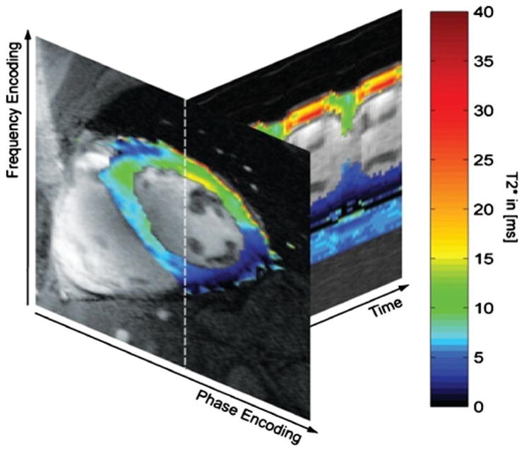
Myocardial T2* color map obtained from 7.0 T gradient echo acquisitions using echo times equally spaced between TE= (3.06–12.24) ms superimposed on the corresponding 2D CINE FLASH image (TE=3.06 ms) together with whole R-R interval time series of 1D projections of T2* along the profile marked by a dotted line in the short axis view. Note the change in T2* across the cardiac cycle. For example, T2* was found to be approximately 15 ms for systolic cardiac phases and approximately 25 ms for diastolic cardiac phases for a region of interest located in the anterior myocardium
Future directions
As 7-T CMR applications become increasingly used for research, they should help to advance the capabilities of MRI for the assessment of heart disease. However, it should be noted that CMR at 7.0 T is still in its infancy and needs to continue to be very carefully validated against CMR applications established at 1.5 T and 3.0 T. For example, first contrast agent passage perfusion imaging and late contrast enhancement studies have not been reported for 7.0 T yet. Although CMR at 7 T is still an emerging area, it may be expected to continue to drive future technological developments. Taking the speed of progress into account, an optimistic practitioner might envision a clinical role for tailored 7-T CMR applications in the future, though this is, for the moment, merely a vision. It is nonetheless a vision that continues to inspire basic and clinical research into CMR at 7 T. The field may still be evolving, but it is also maturing. Demonstrable progress in 7-T CMR technology and methodology is providing encouragement for the imaging community to tackle the solution of the many outstanding issues. Economic and ergonomic requirements are likely to motivate shorter and less expensive magnets and novel radio-frequency hardware tailored for 7 T. One important development on the hardware horizon is the advent of actively shielded 7.0-T MR systems, which will be far more compatible with installations in clinical imaging suites than current models used in basic research requiring hundreds of tons of shielding. Access to shorter magnets —the recently introduced generation of actively shielded 7.0-T magnets has a length of approximately 255 cm, while the passively shielded version runs a length of approximately 336 cm—would be beneficial if not essential to relax ergonomic constraints, to improve patient comfort and to advance interventional CMR applications at 7.0 T. The latter requires extra careful safety measurements including assessment of (1) displacement because of magnetic forces and (2) heating of tissue before interventional and implantable devices—which might be already certified for 1.5 T and 3.0 T—can be declared to be MR safe at 7.0 T. The requirements of CMR at 7.0 T are also likely to pave the way for further advances in RF coil technology, including a broad move to multi-transmit MR systems equipped with eight or more transmit channels. In short, while today’s ultrahigh-field CMR techniques remain in a state of creative flux, productive engagement in this area continues to drive further developments.
Acknowledgments
The authors gratefully acknowledge Mark E. Ladd and Stefan Maderwald (Erwin Hahn Institute, Essen, Germany), Saskia van Elderen and Andrew Webb (Leiden University Medical Center, Leiden, The Netherlands), Thibaut deGeyer d’Orth, Matthias Dieringer, Tobias Frauenrath, Bernd Ittermann, Tomasz Lindel, Fabian Hezel, Florian von Knobellsdorf, Wolfgang Renz and Frank Seiffert (Berlin Ultrahigh Field Facility, Berlin, Germany), all of whom kindly contributed examples of their pioneering work or other valuable assistance.
Contributor Information
Thoralf Niendorf, Email: thoralf.niendorf@mdc-berlin.de, Berlin Ultrahigh Field Facility (BUFF), Max Delbrueck Center for Molecular Medicine, Robert-Roessle-Strasse 10, 13125 Berlin, Germany, Tel.: +49-030-96044504, Fax: +49-030-960449178, Experimental and Clinical Research Center (ECRC), Charité Campus Buch, Humboldt University, Berlin, Germany.
Daniel K. Sodickson, Department of Radiology, Center for Biomedical Imaging, New York University School of Medicine, New York, NY, USA
Gabriele A. Krombach, Department of Diagnostic Radiology, Universtitätsklinikum Giessen und Marburg, Giessen, Germany
Jeanette Schulz-Menger, Berlin Ultrahigh Field Facility (BUFF), Max Delbrueck Center for Molecular Medicine, Robert-Roessle-Strasse 10, 13125 Berlin, Germany, Tel.: +49-030-96044504, Fax: +49-030-960449178, Experimental and Clinical Research Center (ECRC), Charité Campus Buch, Humboldt University, Berlin, Germany, HELIOS-Klinikum Berlin Buch, Berlin, Germany.
References
- 1.Niendorf T, Sodickson DK. Highly accelerated cardiovascular MR imaging using many channel technology: concepts and clinical applications. Eur Radiol. 2008;18:87–102. doi: 10.1007/s00330-007-0692-0. [DOI] [PMC free article] [PubMed] [Google Scholar]
- 2.Kelle S, Nagel E. Cardiovascular MRI at 3T. Eur Radiol. 2007;17(6):F42–F47. doi: 10.1007/s10406-007-0227-4. [DOI] [PubMed] [Google Scholar]
- 3.Gutberlet M, Noeske R, Schwinge K, et al. Comprehensive cardiac magnetic resonance imaging at 3.0 Tesla: feasibility and implications for clinical applications. Invest Radiol. 2006;41:154–167. doi: 10.1097/01.rli.0000195840.50230.10. [DOI] [PubMed] [Google Scholar]
- 4.Gutberlet M, Schwinge K, Freyhardt P, et al. Influence of high magnetic field strengths and parallel acquisition strategies on image quality in cardiac 2D CINE magnetic resonance imaging: comparison of 1.5T vs. 3.0T. Eur Radiol. 2005;15:1586–1597. doi: 10.1007/s00330-005-2768-z. [DOI] [PubMed] [Google Scholar]
- 5.Vaughan JT, Snyder CJ, DelaBarre LJ, et al. Whole-body imaging at 7T: preliminary results. Magn Reson Med. 2009;61:244–248. doi: 10.1002/mrm.21751. [DOI] [PMC free article] [PubMed] [Google Scholar]
- 6.Snyder CJ, DelaBarre L, Metzger GJ, et al. Initial results of cardiac imaging at 7 Tesla. Magn Reson Med. 2009;61:517–524. doi: 10.1002/mrm.21895. [DOI] [PMC free article] [PubMed] [Google Scholar]
- 7.Frauenrath T, Hezel F, Heinrichs U, et al. Feasibility of cardiac gating free of interference with electro-magnetic fields at 1.5 Tesla, 3.0 Tesla and 7.0 Tesla using an MR-stethoscope. Invest Radiol. 2009;44:539–547. doi: 10.1097/RLI.0b013e3181b4c15e. [DOI] [PubMed] [Google Scholar]
- 8.van Elderen SG, Versluis MJ, Webb AG, et al. Initial results on in vivo human coronary MR angiography at 7T. Magn Reson Med. 2009;62:1379–1384. doi: 10.1002/mrm.22168. [DOI] [PubMed] [Google Scholar]
- 9.Versluis MJ, Tsekos N, Smith NB, et al. Simple RF design for human functional and morphological cardiac imaging at 7tesla. J Magn Reson. 2009;200:161–166. doi: 10.1016/j.jmr.2009.06.014. [DOI] [PubMed] [Google Scholar]
- 10.Maderwald S, Orzada S, Schäfer LC, et al. Proc Intl Soc Mag Reson Med. Vol. 17. Honolulu, Hawaii, USA: 2009. Seven-Tesla human in vivo cardiac imaging with an 8-channel transmit/receive array; p. 821. [Google Scholar]
- 11.Hendel RC, Patel MR, Kramer CM, et al. ACCF/ACR/SCCT/SCMR/ASNC/NASCI/SCAI/SIR 2006 appropriateness criteria for cardiac computed tomography and cardiac magnetic resonance imaging: a report of the American College of Cardiology Foundation Quality Strategic Directions Committee Appropriateness Criteria Working Group, American College of Radiology, Society of Cardiovascular Computed Tomography, Society for Cardiovascular Magnetic Resonance, American Society of Nuclear Cardiology, North American Society for Cardiac Imaging, Society for Cardiovascular Angiography and Interventions, and Society of Interventional Radiology. J Am Coll Cardiol. 2006;48:1475–1497. doi: 10.1016/j.jacc.2006.07.003. [DOI] [PubMed] [Google Scholar]
- 12.Zagrosek A, Abdel-Aty H, Boye P, et al. Cardiac magnetic resonance monitors reversible and irreversible myocardial injury in myocarditis. JACC Imaging. 2009;2:131–138. doi: 10.1016/j.jcmg.2008.09.014. [DOI] [PubMed] [Google Scholar]
- 13.Kwong RY, Chan AK, Brown KA, et al. Impact of unrecognized myocardial scar detected by cardiac magnetic resonance imaging on event-free survival in patients presenting with signs or symptoms of coronary artery disease. Circulation. 2006;113:2733–2743. doi: 10.1161/CIRCULATIONAHA.105.570648. [DOI] [PubMed] [Google Scholar]
- 14.Gutberlet M, Spors B, Thoma T, et al. Suspected chronic myocarditis at cardiac MR: diagnostic accuracy and association with immunohistologically detected inflammation and viral persistence. Radiology. 2008;246:401–409. doi: 10.1148/radiol.2461062179. [DOI] [PubMed] [Google Scholar]
- 15.Friedrich MG, Strohm O, Schulz-Menger J, et al. Contrast media-enhanced magnetic resonance imaging visualizes myocardial changes in the course of viral myocarditis. Circulation. 1998;97:1802–1809. doi: 10.1161/01.cir.97.18.1802. [DOI] [PubMed] [Google Scholar]
- 16.Wagner A, Mahrholdt H, Holly TA, et al. Contrast-enhanced MRI and routine single photon emission computed tomography (SPECT) perfusion imaging for detection of subendocardial myocardial infarcts: an imaging study. Lancet. 2003;361:374–379. doi: 10.1016/S0140-6736(03)12389-6. [DOI] [PubMed] [Google Scholar]
- 17.Mahrholdt H, Wagner A, Deluigi CC, et al. Presentation, patterns of myocardial damage, and clinical course of viral myocarditis. Circulation. 2006;114:1581–1590. doi: 10.1161/CIRCULATIONAHA.105.606509. [DOI] [PubMed] [Google Scholar]
- 18.Abdel-Aty H, Boye P, Zagrosek A, et al. Diagnostic performance of cardiovascular magnetic resonance in patients with suspected acute myocarditis: comparison of different approaches. J Am Coll Cardiol. 2005;45:1815–1822. doi: 10.1016/j.jacc.2004.11.069. [DOI] [PubMed] [Google Scholar]
- 19.Cooper LT., Jr Myocarditis. N Engl J Med. 2009;360:1526–1538. doi: 10.1056/NEJMra0800028. [DOI] [PMC free article] [PubMed] [Google Scholar]
- 20.Zhu Y. Parallel excitation with an array of transmit coils. Magn Reson Med. 2004;51:775–784. doi: 10.1002/mrm.20011. [DOI] [PubMed] [Google Scholar]
- 21.Ullmann P, Junge S, Wick M, et al. Experimental analysis of parallel excitation using dedicated coil setups and simultaneous RF transmission on multiple channels. Magn Reson Med. 2005;54:994–1001. doi: 10.1002/mrm.20646. [DOI] [PubMed] [Google Scholar]
- 22.Katscher U, Bornert P. Parallel RF transmission in MRI. NMR Biomed. 2006;19:393–400. doi: 10.1002/nbm.1049. [DOI] [PubMed] [Google Scholar]
- 23.Katscher U, Bornert P, Leussler C, et al. Transmit SENSE. Magn Reson Med. 2003;49:144–150. doi: 10.1002/mrm.10353. [DOI] [PubMed] [Google Scholar]
- 24.Lattanzi R, Sodickson DK, Grant AK, et al. Electrodynamic constraints on homogeneity and radiofrequency power deposition in multiple coil excitations. Magn Reson Med. 2009;61:315–334. doi: 10.1002/mrm.21782. [DOI] [PMC free article] [PubMed] [Google Scholar]
- 25.Schneider JT, Kalayciyan R, Haas M, et al. Inner-Volume Imaging Using Three-Dimensional Parallel Excitation: Simulation and First Experimental Results. Third International Workshop on Parallel MRI; Santa Cruz, CA, USA. 2009. [Google Scholar]
- 26.Zelinski AC, Angelone LM, Goyal VK, et al. Specific absorption rate studies of the parallel transmission of inner-volume excitations at 7T. J Magn Reson Imaging. 2008;28:1005–1018. doi: 10.1002/jmri.21548. [DOI] [PMC free article] [PubMed] [Google Scholar]
- 27.Van de Moortele PF, Akgun C, Adriany G, et al. B(1) destructive interferences and spatial phase patterns at 7T with a head transceiver array coil. Magn Reson Med. 2005;54:1503–1518. doi: 10.1002/mrm.20708. [DOI] [PubMed] [Google Scholar]
- 28.Vaughan JT, Adriany G, Snyder CJ, et al. Efficient high-frequency body coil for high-field MRI. Magn Reson Med. 2004;52:851–859. doi: 10.1002/mrm.20177. [DOI] [PubMed] [Google Scholar]
- 29.Maderwald S, Orzada S, Schäfer LC, et al. Proc Intl Soc Mag Reson Med. Vol. 17. Honolulu, Hawaii, USA: 2009. Seven-Tesla human in vivo cardiac imaging with an eight-channel transmit/receive array; p. 821. [Google Scholar]
- 30.Dieringer MA, Renz W, Lindel T, et al. Proc Intl Soc Mag Reson Med. Vol. 18. Stockholm, SE: 2010. A four-channel TX/RX surface coil for 7.0T: design, optimization and application for cardiac function imaging; p. 3583. [Google Scholar]
- 31.Renz W, Lindel T, Dieringer M, et al. Proc Intl Soc Mag Reson Med. Vol. 18. Stockholm, SE: 2010. A 8 channel TX/RX decoupled loop array for cardiac/body imaging at 7T; p. 1299. [Google Scholar]
- 32.Lanzer P, Barta C, Botvinick EH, et al. ECG-synchronized cardiac MR imaging: method and evaluation. Radiology. 1985;155:681–686. doi: 10.1148/radiology.155.3.4001369. [DOI] [PubMed] [Google Scholar]
- 33.Kugel H, Bremer C, Puschel M, et al. Hazardous situation in the MR bore: induction in ECG leads causes fire. Eur Radiol. 2003;13:690–694. doi: 10.1007/s00330-003-1841-8. [DOI] [PubMed] [Google Scholar]
- 34.Shellock FG, Kanal E. Burns associated with the use of monitoring equipment during MR procedures. J Magn Reson Imaging. 1996;6:271–272. doi: 10.1002/jmri.1880060150. [DOI] [PubMed] [Google Scholar]
- 35.Shellock FG, Crues JV. MR procedures: biologic effects, safety, and patient care. Radiology. 2004;232:635–652. doi: 10.1148/radiol.2323030830. [DOI] [PubMed] [Google Scholar]
- 36.Stralka JP, Bottomley PA. A prototype RF dosimeter for independent measurement of the average specific absorption rate (SAR) during MRI. J Magn Reson Imaging. 2007;26:1296–1302. doi: 10.1002/jmri.21141. [DOI] [PMC free article] [PubMed] [Google Scholar]
- 37.Stecco A, Saponaro A, Carriero A. Patient safety issues in magnetic resonance imaging: state of the art. Radiol Med. 2007;112:491–508. doi: 10.1007/s11547-007-0154-4. [DOI] [PubMed] [Google Scholar]
- 38.Fischer SE, Wickline SA, Lorenz CH. Novel real-time R-wave detection algorithm based on the vectorcardiogram for accurate gated magnetic resonance acquisitions. Magn Reson Med. 1999;42:361–370. doi: 10.1002/(sici)1522-2594(199908)42:2<361::aid-mrm18>3.0.co;2-9. [DOI] [PubMed] [Google Scholar]
- 39.Stuber M, Botnar RM, Fischer SE, et al. Preliminary report on in vivo coronary MRA at 3 Tesla in humans. Magn Reson Med. 2002;48:425–429. doi: 10.1002/mrm.10240. [DOI] [PubMed] [Google Scholar]
- 40.Frauenrath T, Niendorf T, Kob M. Acoustic method for synchronization of Magnetic Resonance Imaging (MRI) Acta Acustica united with Acustica. 2008:148–155. [Google Scholar]
- 41.Becker M, Frauenrath T, Hezel F, et al. Comparison of left ventricular function assessment using phonocardiogram- and electrocardiogram-triggered 2D SSFP CINE MR imaging at 1.5T and 3.0T. Eur Radiol. 2010;20:1344–1355. doi: 10.1007/s00330-009-1676-z. [DOI] [PubMed] [Google Scholar]
- 42.Maderwald S, Nassenstein K, Orzada S, et al. Proc Intl Soc Mag Reson Med. Vol. 18. Stockholm, SE: 2010. MR imaging of cardiac wall-motion at 1.5T and 7T: SNR and CNR comparison; p. 1299. [Google Scholar]
- 43.Brants A, Versluis M, de Roos A, et al. Proc Intl Soc Mag Reson Med. Vol. 18. Stockholm, SE: 2010. Quantitative comparison of left ventricular cardiac volume, mass and function obtained at 7 Tesla with “gold standard” values at 1.5 Tesla; p. 1299. [Google Scholar]
- 44.ICNIRP. Amendment to the ICNIRP “Statement on Medical Magnetic Resonance (MR) Procedures: Protection of Patients”. Health Phys. 2009;97:259–261. doi: 10.1097/HP.0b013e3181aff9eb. [DOI] [PubMed] [Google Scholar]
- 45.von Knobelsdorff-Brenkenhoff F, Frauenrath T, Prothmann M, et al. Cardiac chamber quantification using magnetic resonance imaging at 7 Tesla-a pilot study. Eur Radiol. 2010 doi: 10.1007/s00330-010-1888-2. [DOI] [PubMed] [Google Scholar]
- 46.Frydrychowicz A, Arnold R, Harloff A, et al. Images in cardiovascular medicine. In vivo 3-dimensional flow connectivity mapping after extracardiac total cavopulmonary connection. Circulation. 2008;118:e16–e17. doi: 10.1161/CIRCULATIONAHA.107.761304. [DOI] [PubMed] [Google Scholar]
- 47.van Elderen SGC, Versluis MJ, Westenberg JJM, et al. Coronary magnetic resonance angiography at 7 Tesla: a quantitative comparison with results at 3 Tesla. J Cardiovasc Magn Reson. 2010;12:O88. [Google Scholar]
- 48.Caravan P, Ellison JJ, McMurry TJ, et al. Gadolinium(III) chelates as MRI contrast agents: structure, dynamics, and applications. Chem Rev. 1999;99:2293–2352. doi: 10.1021/cr980440x. [DOI] [PubMed] [Google Scholar]
- 49.Modell B, Khan M, Darlison M, et al. Improved survival of thalassaemia major in the UK and relation to T2* cardiovascular magnetic resonance. J Cardiovasc Magn Reson. 2008;10:42. doi: 10.1186/1532-429X-10-42. [DOI] [PMC free article] [PubMed] [Google Scholar]


