

Abstract
An aberration correction method based on the maximization of the wave intensity at the focus of an emitting array is presented. The potential of this new adaptive focusing technique is investigated for ultrasonic focusing in biological tissues. The acoustic intensity is maximized non invasively through the direct measurement or indirect estimation of the beam energy at the focus for a series of spatially coded emissions. For ultrasonic waves, the acoustic energy at the desired focus can be indirectly estimated from the local displacements induced in tissues by the ultrasonic radiation force of the beam. Based on the measurement of these displacements, this method allows the precise estimation of the phase and amplitude aberrations and consequently the correction of aberrations along the beam travel path. The proof of concept is first performed experimentally using a large therapeutic array with strong electronic phase aberrations (up to 2π). Displacements induced by the ultrasonic radiation force at the desired focus are indirectly estimated using the time shift of backscattered echoes recorded on the array. The phase estimation is deduced accurately using a direct inversion algorithm which reduces the standard deviation of the phase distribution from σ = 1.89 before correction to σ = 0.53 following correction. The corrected beam focusing quality is verified using a needle hydrophone. The peak intensity obtained through the aberrator is found to be −7.69 dB below the reference intensity obtained without any aberration. Using the phase correction, a sharp focus is restored through the aberrator with a relative peak intensity of −0.89 dB. The technique is tested experimentally using a linear transmit/receive array through a real aberrating layer. The array is used to automatically correct its beam quality, as it both generates the radiation force with coded excitations and indirectly estimates the acoustic intensity at the focus with speckle tracking. This technique could have important implications in the field of High Intensity Focused Ultrasound even in complex configurations such as transcranial, transcostal or deep seated organs.
Keywords: Artifacts, Computer-Aided Design, Equipment Design, Equipment Failure Analysis, Image Enhancement, instrumentation, methods, Reproducibility of Results, Sensitivity and Specificity, Ultrasonography, instrumentation, methods
I. Introduction
In wave physics, adaptive focusing is a research topic that encompasses a wide variety of applications ranging from electromagnetic waves in radar or satellite telecommunications [1] [2], ultrasonic waves in underwater acoustics [3] or medical ultrasound [4] and finally optical waves in microscopy or astronomy [5] [6] [7].
Adaptive focusing is based on estimating and then applying time delays (or phase delays for monochromatic waves) on each element of an array to correct differences in the travel path of transmitted or received waves due to medium heterogeneities. Such time delays can be estimated by the echoes from a bright reflector, such as a kidney stone reflecting an incident ultrasonic wave in lithotripsy, or a point like active source such as a star in adaptive astronomy located at the desired focus. In such configurations, the array records the impulse response linking each element in the array to the focal point. From the knowledge of this set of data, the so called Green’s function, one simply has to time reverse the wavefield (or phase conjugate for monochromatic signals) to focus back on the initial source location. For example, time reversal focusing [8] [9] has encountered a significant success in the ultrasound community because piezo-electric transducer technology enables the exact recording and transmitting of broadband signals (i.e. transmission and recording of both amplitude and phase of the wavefield). Time reversal focusing was also extended to heterogeneous and dissipative media by applying the concept of spatio-temporal inverse filters [10] [11] [12].
When it is not possible to rely on the presence of a point-like active or passive source at the desired focus, the spatial coherence of echoes reflected by randomly distributed Rayleigh scatterers can be used to assess such time delays [4] [13]. The coherence between signals received on two neighbouring elements of the array can be used in order to estimate the delays. The Van cittert Zernike theorem, developed for optics and later applied to medical ultrasound by Mallard et al. [14] [15] enables an estimation of the focusing quality in such speckle environment from the spatial autocorrelation of the wavefield recorded on the array. However, in some practical situations and application domains, the measurement of the Green’s function between the array and the targeted focus is not possible. In optics, one has unfortunately only access to the wave intensity so that the phase differences between each receiver or transmitter cannot be estimated. Recently, in the optics community, Vellekoop et al. proposed an interesting way to overcome this technological limitation [16]. They demonstrated the refocusing of optical beams through a multiple scattering medium by estimating only the optical intensity of the beam at the focus. The technique was based on successive modifications of spatial phase distribution of the incident beam using a spatial light modulator (SLM). The implication and potential applications of this method are important in optics because they demonstrated precise control and refocusing of diffuse light through opaque objects.
In the ultrasound community, Urban et al. [17] recently proposed the use of the ultrasonic radiation force as a method for improving the focusing of a phased array through a heterogeneous medium. The basic principle relies on the idea that maximizing tissue displacements induced at the focus optimizes the focusing at this point. Indeed, it is well accepted that local displacements induced at the focus by the ultrasonic radiation force of the beam is proportional to the beam intensity [18]. They proposed an iterative optimization scheme on an element by element basis. While they attempted to focus the beam on a small spherical target through a strong aberrator, they applied a set of phase corrections to each element of the phased array. The phase shift correction was varied for one element of the phased array and the motion of the target was measured consecutively for each correction. The optimized phase correction for this element was assumed to be the one that maximized the amplitude of the target displacement. Once this element was optimized, the optimization of the other elements was then achieved iteratively using the same technique.
This technique may present several drawbacks in a practical implementation. First the relative contribution of a single element to the total acoustic intensity varies as for large N. For example, for a ten-element array a relative increase of approximately 20% of the total intensity is obtained at the focus through the optimization of one element, whereas an increase of only 0.4% can be obtained using a 500 element array. Such small variations of the intensity are barely detectable. For in vivo applications, this method may become completely unusable with large phased arrays that are commonly used in diagnostic ultrasound or in HIFU therapy. A second important issue is the large number of iterations required for the optimization. To achieve the correction, 20 phase changes were necessary for each element of the transducer. As the number of element increases, the number of iterations, and therefore the duration of the optimization, increases rapidly and becomes an important time-limitation. Finally, this focusing technique is not fully optimal beacause the accuracy of the phase correction might not be sufficient after the optimization process for an array with a large number of channels. Two or more correction processes might be necessary to determine the phase with more accuracy.
In this paper, we propose a general concept of energy-based adaptive focusing approach that could be applied in various domains of wave physics. Similarly to Vellekoop et al. and Urban et al., it is base on the idea of estimating the beam intensity at the focus for successive and different illuminations. This is the semantic origin of the “energy-based” terminology. In optics, this technique should strongly improve the sensitivity of previous work. In the context of medical ultrasound, the approach proposed in this paper presents the advantage to be applicable in-vivo using arrays with a large number of channels and provides a direct estimation of the optimal aberration correction. The principle relies on the use of the radiation force generated by the ultrasonic beam at the target location. This ultrasound radiation force has been used in soft tissue elasticity imaging to image the viscoelastic properties of tissues through the generation of shear waves [18] [19] or the motion induced at the focal zone [20].
Contrary to the previous techniques, we propose to optimize the phases of each element of the transducer array all at the same time by using spatially coded emissions. This is done by defining virtual transducers from linear combinations of the array elements. Based on measurements of tissue motion (indirectly linked to the local beam energy), the phase aberration between two of these virtual transducers can be measured using a limited number of acquisitions. Because all elements of the array are used for each illumination, a first advantage for in vivo applicability of the method lies in the strong improvement of signal to noise ratio (SNR) at the measurement location. Once the phase shifts are obtained for all the virtual transducers, the phase aberrations as well as the amplitude aberrations can be derived. Based on a direct and non iterative inversion algorithm, this technique allows an optimal focal spot to be restored non-invasively and can be applied to a large number of elements with a good accuracy while drastically reducing the acquisition time. In this paper, the optimization technique is described as well as the experimental setup. Experimental results demonstrate the potential of this technique using a transducer composed of 64-elements focusing through strong phase aberrations. In this paper, the local displacements induced by the radiation force are estimated by the ultrasonic array via speckle tracking of backscattered echoes.
The theoretical framework of our technique is presented in the first section of the paper. In the second section, this new focusing approach is applied in a first experimental setup to learn how to autofocus the ultrasonic beam onto a point-like reflecting target. The goal of this roof of concept” experiment is to demonstrate the efficiency of the technique in a simple configuration. The third section deals with the application of the technique in a much more realistic configuration for medical applications in which the backscattering medium is made of very small Rayleigh scatterers randomly distributed in space, i.e. speckle environment and does not contain any bright specular reflector. Finally, potential applications and limitations of the technique are discussed in the last section.
II. Theory
In this section, a theoretical framework is developed to estimate directly the phase and amplitude aberrations for multielement ultrasonic arrays using indirect measurements of the beam intensity. This method relies on the assumption that maximizing the radiation force at the focal point optimizes the acoustic intensity at the same point. Indeed, the acoustic radiation force generated in biological tissues is assumed here to be linearly related to the acoustic intensity. The local force per unit of volume generated by an ultrasound beam in tissues can be written as:
| (1) |
where I is the acoustic intensity, α is the attenuation coefficient of the tissue, c is the speed of sound and ez is the direction of the wave propagation.
Here we assume that the ultrasonic array is composed of N elements working at the same frequency in continuous mode and generating the same acoustic pressure p0 at the focal point. If an aberrator is placed between the focal point and the ultrasonic array the contribution of the element number n at the focal point becomes: pn(t) = Anp0eiΦneiωt where Φn and An are respectively the phase and the amplitude aberration and ω is the angular frequency. Therefore, the total intensity at the focal point is given by:
| (2) |
where Z is the local acoustical impedance of the medium at the focal point. Equation 2 shows that the total intensity at the focus is given by the modulus of the sum of the complex amplitudes AneiΦn. We will show now how to determine Φn and An based on intensity measurements.
A. Determination of a phase shift between two transducers
In the case of only two transducer elements, the acoustic intensity at the focus through the aberrator is:
| (3) |
with Φ = Φ2 − Φ1 When an additional phase shift x in introduced in the wave transmitted by the second transducer, the intensity measured at the focus is modulated by a cosine function of x:
| (4) |
In order to determine Φ, this problem can be written as a linear equations system with 3 unknows: B, C cos(Φ) and C sin(Φ).
| (5) |
This system is solvable if the intensity is measured at least for three different values of x in the range [0 – 2π]. Then Φ is derived immediately, solving the phase aberration problem.
B. Generalisation to N-element array using spatially coded emissions
The technique described previously for two elements cannot be applied directly to the case of multielement arrays. The main reason is that the intensity generated by the combination of two small elements of a large phased array is too weak to generate any detectable radiation force effect. We propose here to solve this problem and generalize the previous technique by defining “virtual” elements that are composed of linear combinations of all the elements of the phased array.
Note Tn the complex amplitude of the monochromatic signal transmitted by the nth element of the phased array. The contribution of this element to the pressure field received at the focal point is pn = GnTn = AneiΦn where Gn is the complex amplitude of the Green’s function relating element n and the focus. A basis transformation is performed and a new basis of virtual transducers is defined which are represented by their complex amplitudes:
| (6) |
The transformation basis matrix H must be chosen such as that each vector V is a combination of all the phased array elements. In this paper we propose to use a basis transformation based on the Hadamard decomposition. Taking advantage of the properties of the Hadamard matrix (composed only of 1 and −1), each virtual transducer of this new basis can transmit the full power capability of the array and thus, the effects of the radiation force generated by one of these virtual elements can be detected. Using the same method than for two transducers, two virtual transducers are used with an additional phase shift x. We propose the following combinations of virtual transducers: V0 + Vm, V0 − Vm and (V0 + Vm)eix + (V0 − Vm)e−ix where V0 is a virtual transducer used as reference, Vm is the mth virtual element and x is a phase shift arbitrary chosen. The choice of these combinations was based on the fact that the signals transmitted by the real transducers have the same amplitude on each channel.
The pressure field Pm generated at the focus by the virtual transducer Vm is:
| (7) |
Let us first consider a transformation basis matrix H that is based on the Hadamard decomposition:
| (8) |
for m = 1 the combinations are :
| (9) |
One can notice that the transmit amplitudes in Eq. 9 are either equal to 0 or 1. This allows the use of a simple transmit electronics with binary efficient transmitters.
The intensity at the focal point I induced by the first combination is:
| (10) |
with V̅m the complex conjugate of Vm. This gives:
| (11) |
Proceeding with the same method for the second combination, I2m, we find that:
| (12) |
Here, P0 = B0 exp(iΨ0) is defined as the reference vector, and we fix arbitrarily its phase and amplitude B0 = 1 and Ψ0 = 0. Therefore we obtain:
| (13) |
For the third combination (P0 + Pm)eix + (P0 − Pm)e−ix = 2(P0 cos x + iPm sin x), the intensity at the focus is:
| (14) |
| (15) |
Two mesurements of I3m (x) can be performed with two different phase shifts x. If we fix the two phase shifts as following: x1 = π/4 and x2 = −π/4, we find the imaginary part of Pm:
| (16) |
Finally, once the real and imaginary parts of pressure field at the focus Pm = BmeiΨm are measured by this method, the pressure field received at the focus pn for each transmit element Tn can be derived using the inverse of the matrix H:
| (17) |
One should notice that using this method both the phase aberrations Φn and the relative amplitudes of the wave through the aberrator An are retrieved. Therefore, in order to correct the phase aberrations, one has to correct the transmitted signals with an additional phase φn = −Φn This enables to create constructive interferences at the focus.
III. Basic concept experiment
A. Experimental setup
In order to show the feasibility of this technique a first “proof of concept” experiment was performed using a strong reflective target at the desired focus location.
A 64 elements phased array, previously described [21] was used for both the generation and the measurement of the target displacement. This array was driven by a transmit/receive multichannel electronic platform. The electronics allowed us to transmit arbitrary signals waveforms (sampling rate 30 MHz, Peak Amplitude 40 Volts) individually and simultaneously on each of the 64 elements. The array was fixed on the side of a tank (450 mm both for width and depth, 400 mm high, see Fig. 1). The phased array was spherically curved and was geometrically focused at a 140 mm focal depth. Tansducers were working at a central frequency of 1 MHz. The reflecting target was a small stainless steel sphere (diameter 1.5 mm) embedded in the center of a soft phantom. This phantom consisted of a 10% polyvinyl alcohol (PVA) cryogel (75×50×20 mm), which was formed by freezing and thawing an aqueous PVA solution [23]. The phantom was homogeneous and underwent one cycle of freezing and thawing. The average shear modulus of the background material was 40 kPa estimated using Transient Elastography [19] which agreed with values from literature [23] for a 10% PVA solution after one cycle of freezing and thawing. The phantom was fixed to a 3D micro-control plates which allowed a good positioning accuracy (about 1 μm). Displacement and position of the micro-control plates were computer controlled.
Figure 1.
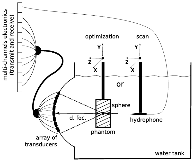
A 64 element phased array was used to perform the focusing optimization on a spherical target embedded in a phantom.
In this proof of concept experiment a numerical aberrator was introduced by adding electronically supplementary individual time delays (i.e. phase delays for long bursts) on each transmit signal. This set of time delays mimicks a real and infinitely thin aberrating layer located very close to the array, known as “phase screen aberator”. These phase aberrations were generated randomly in the range [0 – 2π] for the 64 channels.
B. Ultrasonic Sequences
The sphere embedded in the phantom was positioned in the vicinity of the geometrical focus using the 3D micro-control plates. A simple trick was used in order to avoid very precise and fastidious positioning of the target at the exact geometrical focus. The Green’s function of the spherical target was obtained by successive time reversal operations: first a short impulse (2 cycles, 1 MHz) was emitted by a central element of the array. The resulting wavefront is widely spread in space during propagation and the backscattered echo of the spherical target was received by each transducer of the array. Then, the received signals were normalized, time reversed and finally emitted again. This process was repeated typically 4 or 5 times in order to reach the optimal set of transmit signals focusing on the sphere in a homogeneous medium configuration.
In order to obtain a measurable target displacement from the ultrasonic radiation force, bursts of ultrasound were transmitted during several hundreds of micro-seconds. To optimize the mechanical excitation on the spherical target, the “push” transmit signal (TRpush) was obtained from the convolution of a sinusoidal signal at 1 MHz with the transmit signals corresponding to the Green’s function of the sphere and acquired during the iterative time reversal calibration.
The timing of the transmit sequence was composed of one “push” transmit signal interleaved between two pulses-echo signals (Fig. 2). The target’s initial position was given by the echo of a first pulse. The target was then pushed thanks to the radiation force of the “push” transmit signal. The burst duration was 400 μs and the amplitude was 36 V leading to a peak pressure at the focus of 5 MPa. The last step consisted of measuring the target’s new position using a second pulse echo right after the push, typically after 25 μs.
Figure 2.
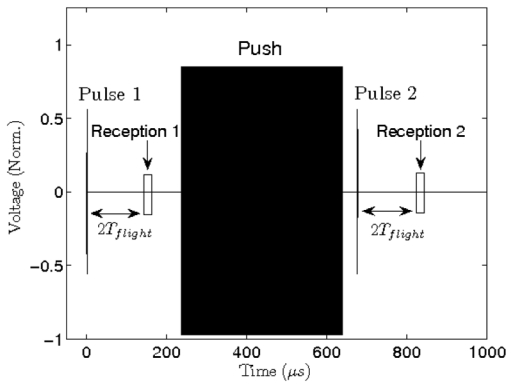
Typical pulse+push+pulse experimental sequence. The positions of the spherical target was determined after and before “pushhanks to pulse echo acquisitions. All transmit signals were aberrated using the random phase shift screen (phase shift for each element), in the range [0 – 2pi].
a. Displacement measurement
The displacement of the spherical target was estimated using a conventional cross-correlation algorithm performed on consecutive pulse-echo RF signals. An important advantage of this method was the possibility of measuring the motion of the target using the same transducers than for the radiation force sequence. All the elements were used in pulse-echo mode using the optimized focusing law. The received signals were beamformed using the same focusing law. A window of 500 points that corresponds to 10 μs was selected around the echo of the target on the beamformed RF signal. A cross-correlation was performed on the signals aquired before and after the push to find the relative displacement (see Fig. 3).
Figure 3.
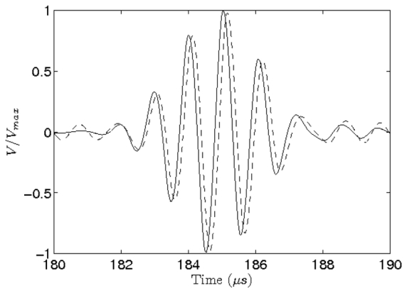
Pulse echoes of the spherical target recorded on the array, respectively before (solid line) and after (dashed) the emission of the “pushing” beam. Amplitude is normalized, t=0 corresponds to the emission of the pulse. We observe a time shift (Δt = 0.12 μs) which corresponds to a displacement of 89 μm of the sphere.
C. Adaptive focusing experiment
b. Transmit codes
As described before, this method was based on spatially coded emissions. It required the emission of 4 signals for each virtual transducer that were calculated by linear combinations of columns of the Hadamard’s matrix, V0 + Vm, V0 − Vm and (V0 + Vm)eix + (V0 − Vm)e−ix where Vo was the first vector used as a reference and x was set successively to −π/4 and π/4. For one given combination, the phase and the amplitude of the emission signal of each element were computed based on the value of the complex amplitude of the vector and the phase aberration. Each combination was successively emitted and the received signals were averaged 5 times using the pulse/push sequence (see above).
c. Data processing
For each virtual transducer, the displacement of the target was measured for the 4 combinations. The real and imaginary part of the complex amplitude BmeiΨm associated to this virtual transducer was then calculated as explained in § II-A and II-B. The complex amplitudes of the elements were obtained by the multiplication of the inverse of the hadamard matrix H and BmeiΨm (see Eq. 17).
D. Assessment of the efficiency of the adaptive focusing process
d. Hydrophone scan
In order to test the efficiency of this method, we compared the focus quality at different stages of the optimization process. The focal area was scanned in the XY directions (see Fig. 1) using a needle hydrophone (diameter of the sensitive surface is 400 μm, Speciality Engineering Associates, PZT-Z44–0400). It should be noted that the speed of sound in PVA phantoms is very close to the speed of sound in water at 20 °C [25] so that no difference could be observed when we replaced the phantom by the hydrophone. The phantom was replaced by the hydrophone at the focal point with a good accuracy (better than hydrophone’s diameter) thanks to successive linear scans following XYZ directions. Once the hydrophone was in the focal area we scanned a map around the focal plane (10 mm side, 0.5 mm step).
E. Results
1. Displacement
a. Displacement dependence of the excitation voltage
First, the displacement amplitude of the target was investigated as a function of the excitation voltage. The experimental emission sequence was composed of 2 imaging pulse used for the motion estimation and an optimized push function (TRpush). Its duration was 400 μs. We increased the excitation voltage of the push emission signal in the range of 4 Vpp to 80 Vpp, the amplitude of the imaging pulse remained unchanged (48 Vpp). Results are shown on Fig. 4: the displacement amplitude is a quadratic function of the voltage and there is no saturation at high voltage. It shows that the measured displacement is proportional to the the acoustic intensity in the full range of avalaible power. This confirmed the linear assumption:
| (18) |
made from Eq. 1 and with K represents the stiffness of the phantom, Δd the displacement and P the pressure on the relationship between acoustic radiation force and pressure. We choose 0.8 as a typical voltage amplitude for the push signal in all the other experiments.
Figure 4.
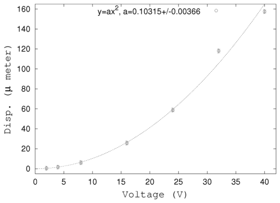
Displacement as a function of the normalized excitation voltage. The push duration was 400 μs. Displacements were measured as explained in § III-B.
b. Estimation of the displacement
Fast transmit of successive imaging pulses after the push emission allowed us to follow the complete motion of the spherical target until it returned to its initial position. 12 imaging pulses were performed at a Pulse Repetition Frequency (PRF) of 4000 Hz. Results are shown Fig. 5. We observe a maximum displacement of Δt = 0.2 μs for the fourth pulse echo acquisition. It corresponds to a displacement of using the speed of sound at 20 °C, 1 bar. Displacement increases rapidly and briefly after the push. The target then slowly returns to its equilibrium position. In the further part of this study we choose to measure the displacement in this increasing part, using pulses n°2 and 3.
Figure 5.
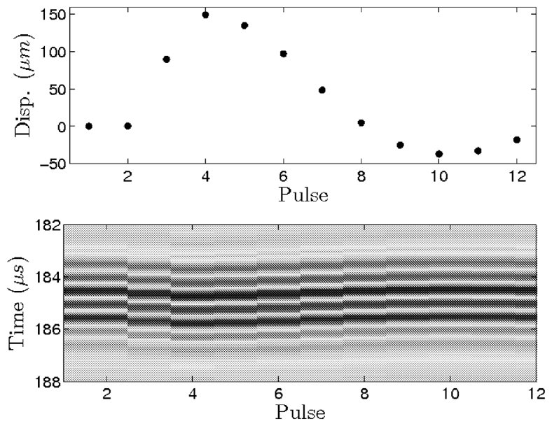
Pulse echoes at different time steps during the “pushing” sequence. Each imaging pulse is separated from the other by 250 μs (PRF=4000 Hz) except for the transmission of the push between pulses 2 and 3. Time starts from the beginning of the pulse echo acquisition.
2. Correction of the phase aberration
a. Phase correction
Even though the phase aberrations led to a displacement less than 5 times smaller than without aberrator, it was always measurable with a good accuracy. Typical experimental displacements measured during the correction process were in the range of 0–15 μm and the average value was 5 μm.
We tested this method with a value of the phase aberration amplitude of 2π. We show on Fig. 6 the phase difference D2π between the numerical aberration introduced in the experiment and the phase correction estimated through our technique after 2 successive experiments. We observe that D2π is small (standard deviation σD2π = 0.53) compared to the phase aberration (standard deviation of the phase is σ =1.89). Comparison between phase aberration and phase correction is reported on Fig. 6.
Figure 6.
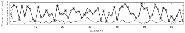
Phase aberration (thick solid line), phase correction (★, dashed line) and sum of them (thick dotted line) for the 64 elements. We show here results obtained after two successive corrections.
b. Optimized focusing
Fig. 7 shows several hydrophone scans map of the pressure field performed at different stages of the experiment (time reversed, through the phase aberrator and with the energy-based adaptive focusing corrections) in the focal area, normalized by the value of the maximum acoustic intensity measured using the time reversed phase. The acoustic intensity in the focal area was almost completely restored after correction and the relative weight of the secondary lobes decreases.
Figure 7.
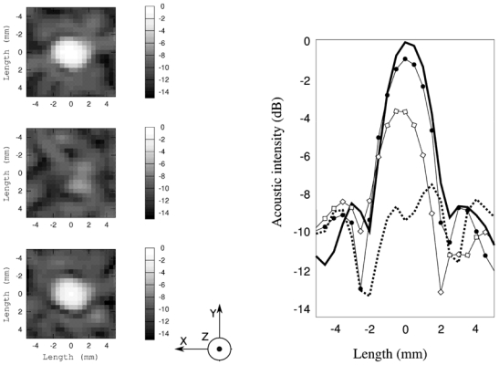
Left part, pressure field map of the focal plane measured by a hydrophone at different stages of the correction, of the scans are 10 mm by 10 mm, with a spatial step of 0.5 mm. Axes from Fig. 1 are represented. From top to bottom: The pressure field obtained using time reversed focusing (used here as a reference), through the aberrator and through the aberrator with the second phase correction. Relatives amplitudes are shown on the right part: the ideal time reversal focusing pattern (thick line), through the aberrator (thick dotted line), after the first correction (◇), and after a second correction (●)
The phase aberrator leads to a drop of the peak pressure at the focus of −7.69 dB, which gives a main lobe of about the same amplitude than the secondary lobes. The focusing quality is strongly degraded and the spatial peak is shifted by 1.5 mm. After a first energy based adaptive focusing correction, the focal area was restored, with the main lobe, slightly shifted (−0.49 mm) and the pressure peak at −3.72 dB (3.75 mm at −6 dB). The main lobe is clearly discernable from the secondary lobes. A second correction based on the result of the first correction, led to a complete restoration of the focusing quality with a main lobe centered and a peak that reaches the value of −0.89 dB and 3.5 mm width at −6 dB.
c. Sensitivity of the autofocusing process to the noise level
The robustness of the autofocusing process to the experimental noise was investigated. A gaussian random noise was added numerically to the measurements of the displacement acquired previously. The standard deviation σnoise of the gaussian distribution σnoise was varied within the range 0 (no additional noise) to the maximum measured displacement. The noise was applied to the successive experiments performed. Then for each value of the noise level the phase correction and finally the pressure restored at the focal point were computed. Fig. 8 shows the normalized pressure at the focal point as a function of the normalized standard deviation of the noise σ̅noise (for a perfect correction we would obtain a normalized pressure of P(σ̅noise) = 1.12).
Figure 8.
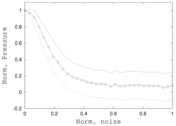
Sensitivity of the autofocusing process to the noise level: Normalized restored pressure at the focal point as a function of the normalized noise (○). Each point is a 100 computations average, dotted lines are the standard deviations.
This results allows us to assess the robustness and the stability of this technique:even with a noisy measurements of the intensity (for instance, σ̄noise = 0.1 i.e 10% of the displacement), the pressure restored at the focal point remains 80% of the optimal value, which still represents a strong improvement of the focusing.
IV. Focusing without reflective target using the speckle noise
Beyond this “proof of concept” experiment performed on a reflective target, a second experiment in a more realistic setup for in vivo application is presented here. The adaptive focusing approach is evaluated through a physical aberrator in a speckle environment, in other words without any bright reflector. A tissue-mimicking phantom was used in order to estimate tissue displacements at the focus.
A. Experimental setup
We used 64 of a 128 element linear imaging array (7.5 MHz central frequency, pitch 0.3 mm, Vermon, France) driven by a multichannel fully programmable electronics (sampling rate in E/R 50 MHz, Amplitude 80 Volts peak to peak). A cylindrical phase shift law was added to the transmit signal in order to set the focal length at 29 mm so that f/D = 1.5 (with f the focal distance and D the aperture). All the array elements were used in transmit and receive for the radiation force generation and also for the motion estimation. The motion of the target zone was estimated using similar pulse echo sequences than described in the previous section. The received signals were beamformed and the motion of the target zone was computed using the cross-correlation between the signals before and after push. A window of 2 μs was selected around the target zone for that purpose.
d. Target
In this experiment, two successive phase optimisations were made for comparisons. First, using a reflective target located at the focal point and the same phantom as described above (see III-A), we determined the phase aberration and operated a phase optimisation process similar to what was done in the previous section. Secondly, the reflective target was replaced by a random distribution of Rayleigh scatterers contained in the phantom (cellulose powder, 1% w/w). The intent was here to mimick speckle noise backscattering occurring in medical ultrasound. In this case displacement was directly estimated at the desired focus from the cross correlation of speckle backscattered echoes corresponding to successive insonications.
e. Physical aberrator
A real “phase aberrator” was used in this experiment. This aberrator consisted into a 1 mm thickness slice of latex placed directly at the surface of the linear array. Only the half central part of the array was covered by the latex sample (elements 14 to 47).
B. Results
f. Phase and amplitude aberration
A first experiment using the physical aberrator was performed using a small stainless steel sphere (∅1 mm) embedded in the phantom and positioned at the focal point. Using this strong reflective target, an optimisation experiment was first perfomed using the energy based adaptive focusing technique. We also acquired an echo of the reflective target in order to characterize quantitatively the physical aberrator (see Fig. 9). The phase distribution exctracted from these signals was considered as a gold standard.
Figure 9.
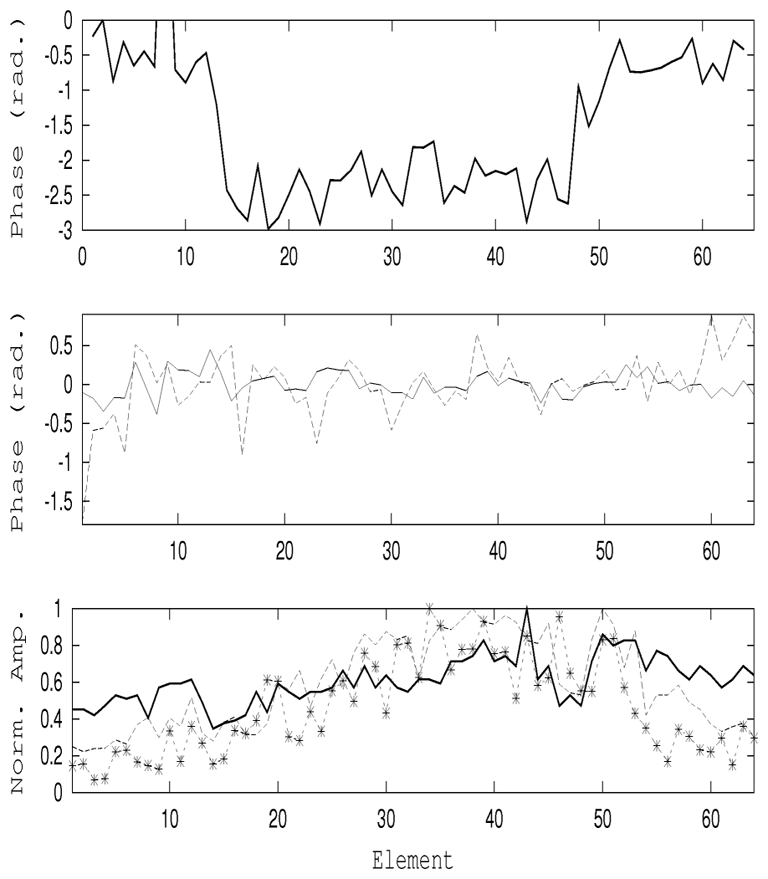
Focusing through a physical aberrator: the true phase aberration (top) law was measured from the backscattered echo of the spherical target. The quality of the adaptive correction can be seen (middle) from the difference between the phases from pulse echo and te phases obtained from the energy-based technique performed on the sphere (solid line) and in the speckle noise (dashed line). Finally, the corresponding normalized amplitude aberrations are shown (bottom) for the aberrated (solid), on the sphere (dashed) and in the speckle (*, dashed) experiments.
In a second experiment, the phased array was moved to another part of the phantom and we performed an energy based adaptive focusing experiment in speckle.
In these experiments one should notice that both transmit and receive are strongly aberrated, both for radiation force pushing and for displacement tracking. The same transmit parameters (amplitude and duration) were used for the “pushing” emission signals in both experiments. After performing the optimisation process, the estimated phase correction was substracted from the reference phase aberration. The estimated phases and normalized amplitudes corrections are shown on Fig. 9 and in Tab. IV-B0f.
When applying the optimisation process to the speckle environment, the standard deviation of the phase error decreased to σspec = 0.35, if we exclude the 5 firsts and the 5 lasts elements for which the relative intensity was extremely weak.
The normalized acoustical intensity I was estimated at the focal point for both focusing corresponding to the optimization process applied respectively using the speckle noise environement (Ispec) or using the spherical target (Isphe) Through the aberrator, the intensity was estimated to be Iaber = −3.02 dB. Using the sphere, we were able to restore almost completely the focus with an intensity of Isphe = −0.21 dB. Finally, using the speckle, the result was in between Ispec = −1.49 dB.
The aberration profile of the real aberrator estimated using the optimisation process was very well recovered using the small target configuration. The optimisation process applied in speckle was less efficient but the correction allowed us to reduce the effect of the aberration and increase the acoustical intensity at focus by a factor of 2.
V. Discussion and conclusion
The work presented in this paper corrects phase aberrations for ultrasonic multichannel arrays using a method based on the maximization of radiation force induced displacement coupled to spatially coded emissions. By transmitting Hadamard coded signals, this technique uses all the array elements for each transmission and therefore uses the full power capability of the array. A strong numerical aberration (up to 2π) was first corrected by the remote detection of the radiation force induced motion of a small target embedded in homogeneous soft tissue. Then, using a smaller physical aberrator we have shown the feasibility of using this method in a tissue mimicking phantom without strong reflective targets. Fig. 7 shows that the phase aberration is very well recovered, even without spatial correlation of the phase aberration between closest elements. To measure the three unknowns in Eq. 5, 3 different measurements of the intensity at the focal point are performed for each element. In our experiments, we added a constraint that accounts for the 2 bit transmit dynamics (i.e. only able to transmit emissions only with normalized amplitudes of 0, 1 or −1). Although only three insonifications are theoretically needed for estimating the optimal phase delay between two Hadamard transmit vectors, this constraint requires a fourth measurement of the intensity to ensure the robustness of the estimation. As a consequence, the phase aberration correction of an N elements array requires 4N successive transmissions. The proposed method strongly reduces the time needed to perform the entire correction process compared to iterative approaches because it is not necessary to explore the full range of possible phase values for each element.
This adaptive focusing method offers major advantages. Indeed, beams (corresponding to sonic, ultrasonic, optical or electromagnetic waves) transmitted by an array can be corrected and refocused at a desired location using the direct or indirect measurement of the beam intensity. Direct estimation can be performed easily using a single probe at the focal point. Indirect measurements can be performed with a measurement of the beam’s effects on the medium following insonification, such as, for example, tissue displacement due to the beam radiation force or local temperature increase due to beam absorption. For many configurations, this indirect estimation at the focus can be done remotely with, for example, an echographic probe or a MR system in the case of ultrasound beam focusing. Therefore, depending on the application and potential configuration, there is no need for a probe at the focal point.
In this study, wave propagation was assumed to occur in a linear regime. However, for high pressure fields used in HIFU and ultrasonic imaging at high Mechanical Index, wave propagation becomes nonlinear. Signal distortions becomes non negligible mainly in the focal area. This non-linearity affects the acoustic radiation force as higher harmonics generated by the nonlinear propagation results in higher ultrasonic absorption effects at the focal spot. This leads to an overestimation of the acoustic intensity based on Eq. 1 obtained in the linear regime. Therefore, it is important to work within a linear range of acoustic power. This can be ensured by performing the optimization process using transmit signals with lower amplitude and by increasing the transmit voltage only after the aberration correction process. Another solution consists of measuring tissue displacement as a function of the transmitted power or voltage over a large power range, as it was shown in Fig. 4.
In our experiments the duration of the successive transmits required for the optimization was less that 130 ms. However, due to data transfer limitations of the hardware, the entire process took approximately 45 minutes. The “pushing” emission signals was a matrix of 400 μs×30 Ms length and 64 elements width on 8 bits and the low data transmission of our electronics slowed down the experiment considerably. The duration of the experiment could be deeply reduced by increasing the transmission ratio and by computing the different signals before the experiment. With a fully optimized hardware, the complete adaptive focusing process would take less than some seconds.
Safety issues should also be considered for medical applications because the number of ultrasonic shots required for adaptive correction can be large in the case of arrays with many elements. In our experiments we did not try to optimize the total energy of the acoustic beam. Nevertheless, the largest negative pressure found in the study was 3.2 MPa which corresponds to a Mechanical Index of 1.1 at a 7.5 MHz central frequency. This value is far below the F.D.A requirements for cavitation issues. In terms of acoustic energy deposition, at least 40 insonications of 50 μs burst duration could be performed per second while remaining below the F.D.A. requirements for the Ispta value (spatial peak time average Intensity < 720 mW/cm2). This number of insonications per second could even be increased because pressure field at the focus is only at its maximum level value for a limited number of shots during the optimization process.
Another advantage of this method is that the quality of the phase correction does not depend on the timing of the experimental acquisitions as is the case for an iterative inversion process. In iterative approaches, the phase of the elements are corrected one by one with direct adjustment of the phase. The accuracy of the correction is better when most of the array is already corrected than when most of the array is defocused. In our case, the optimization is based on a direct inversion that avoids such problems.
We have seen in Eq. 17 that the optimization method allows us to determine both phase and amplitude corrections. In this paper we used the phase correction to improve the contrast of the focal point in an imaging experiment and to balance the distortion of the focusing due to the assymetrical contribution of the elements of the phased array. The optimization process gives also access to the amplitude correction that also permit to optimize the transmit amplitude on each channel for an optimal ratio between acoustic energy deposition at the focus and transmitted energy from the array. This optimization process is closely linked to the concept of time reversal focusing which provides a spatio-temporal matched filter [10] of wave propagation between the array and the focal point.
This technique has several applications in medical ultrasound, such as aberration correction in diagnostic imaging or in therapeutic ultrasound. In diagnostic imaging, the added value of this aberration correction technique has yet to be proven. The major issue in diagnostic imaging is the time requested for correcting the aberrations which needs to be compatible with real time imaging. To date, we need 3xN ultrasonic insonifications to fully correct any kind of aberration whatever its spatial complexity. However this number could be strongly reduced in the case of aberrating layers with large correlation lengths. Indeed if the correlation length of the aberrator is large compared to the array’s pitch, it could be possible to restrict the method to the use of the Hamadard vectors that vary slowly in space. For a 128 imaging array focusing at a typical 40 mm depth, the number of degrees of freedom of the propagation operator is much lower than 128 (40 in refs [24] and [22]). So, there is an emission vector basis with a fewer degrees of freedom that would be better adapted to the case of medical imaging with slowly varying aberrating layers (as is the case in breast or liver). For these cases the number of insonifications would be strongly decreased and the correction could be performed in a few tens of milliseconds.
An immediate and extremely interesting application of this aberration correction method is in therapeutic ultrasound especially in the case of strongly aberrating layers. In conventional therapeutic applications, such as fibro-uterin, breast or liver HIFU, the HIFU array can both transmit pushing pulses and record tissue displacement, thus providing a complete autocorrection of the ultrasonic beam. In complex cases, such as transcranial ultrasonic focusing, one cannot rely on the backscattered echoes due to strong absorption in the skull bone. Moreover the speckle tracking technique used for tissue displacement estimation cannot be performed because strong skull aberrations dramatically degrade the beam quality. In these cases, a MRI system could be used to overcome these limitations. Since MR scanners will be coupled to HIFU for the application of transcranial brain therapy, this would have some important clinical advantages such as the ability to determine the focusing zone under MR guidance and the real time control of the phase correction process.
In the case of large aberrations we demonstrated that radiation force induced displacements are large enough to be detected by ultrasound pulse echo sequences. In the case of smaller aberrations and tissue displacements the auto-focusing process was still efficient. It provides an efficient way to autofocus the ultrasonic beam using transmit/receive ultrasonic arrays. Current work is focused on evaluating the proposed approach for complex in vivo cases where radiation force induced displacements cannot be estimated with ultrasonic speckle tracking. In such cases, the ultrasonic measurement of tissue displacement can be replaced a motion sensitive MRI sequence capable of measuring small tissue displacements (of the order of 1 μm). For example, in medical ultrasound, transcranial focusing is a very complex task for two reasons: first, the skull induces strong aberrations. Second, the speckle noise backscattered by brain tissue micro-heterogeneities is strongly absorbed by the skull and consequently cannot be recorded and used by the ultrasonic array for adaptive corrections. For such configurations, the array can be driven only in the transmit mode as is currently the case in most ultrasound therapy systems. This adaptive focusing technique may potentially be used for HIFU brain or liver therapy applications under MRI guidance. Finally, beyond ultrasound applications, the proposed optimization process could be transposed to optics for focusing light in diffuse medium.
Figure 10.
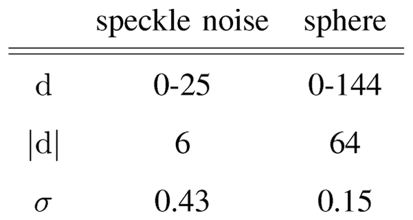
Displacement range (μm), average displacement and standard deviations of the phase difference after the energy-based focusing using the speckle noise and the reflecting target
Biographies
Eric Herbert was born in April 1979 in Paris, France. He received his M.S. degree in 2003 and his Ph.D. in physics (thermodynamic) in 2006 from University Paris Diderot for his work on acoustic cavitation in pure water. He worked as a postdoctoral researcher at the Laboratoire Ondes et Acoustique (ESPCI, Paris, France) in the ultrasound and elasticity imaging. He is currently a postdoctoral researcher in wave turbulence at the laboratory Matière et Système Complexe at University Paris Diderot.
 Mathieu Pernot was born in November 1977 in St. Jean de Maurienne, France. He received an engineering degree in Physics from Ecole Supérieure de Physique et de Chimie Industrielles de Paris (ESPCI) in 2001. He received his M.S. degree in 2001 and his Ph.D. in physics (ultrasonics) in 2004 from University Paris VI for his work on transcranial High Intensity Focused Ultrasound brain therapy and ultrasound-based monitoring. He worked as a postdoctoral researcher in the ultrasound and elasticity imaging at Columbia University (New York, NY, USA) and as a research scientist at SuperSonic Imagine (Aix en provence, France). He is currently a researcher of Institut National de la Santé et de la recherche Médicale in France (INSERM) at the Laboratoire Ondes et Acoustique in Paris, France. His current research interests include HIFU brain therapy, wave focusing in heterogeneous media, medical ultrasound therapy, elasticity imaging of cardiovascular tissues.
Gabriel Montaldo
 Mathias A. Fink received the diplome de Doctorat de 3ème cycle in solid state physics in 1970 and the Doctorat ès-Sciences degree in acoustics in 1978 from Paris University, France. From 1981 to 1984, he was a professor of acoustics at Strasbourg University, France. Since 1984, he has been a professor of physics at Paris University (Denis Diderot), France. In 1990 he founded the Laboratoire Ondes et Acoustique at the Ecole Supérieure de Physique et de Chimie Industrielles de la Ville de Paris (ESPCI). In 1994, he was elected at the Institut Universitaire de France. His current research interest include medical ultrasonic imaging, ultrasonic therapy, nondestructive testing, underwater acoustics, active control of sound and vibration, analogies between optics and acoustics, wave coherence in multiple scattering media, and time reversal in physics. He has developed different techniques in speckle reduction, wave focusing in inhomogeneous media, and in ultrasonic laser generation. He holds 20 patents, and he has published more than 220 articles. In 2003, he was elected at the French Academy of Science.
 Mickaël Tanter was born in December 1970 in France. He received the Ing. degree in Electronics of SUPELEC in 1994. In 1999, he received the Ph.D. degree in Physics (Acoustics) from the University of Paris VII for his work on the application of time reversal to ultrasonic brain therapy and the “Habilitation de Recherche” in 2004. From 2000 to 2005, he has been an Associate Professor of the french center for scientific research (CNRS) at ESPCI, Paris, France. In 2005, he became a Research Professor of the french institute for medical research (INSERM). He is currently the head of the research team “Wave Physics for Medicine” at the Laboratoire Ondes et Acoustique (ESPCI), laboratory directed by Mathias Fink. His current research interests include ultrasonic imaging and therapy (adaptive focusing techniques in heterogeneous media, medical ultrasonic imaging, ultrasonic brain imaging, shear wave propagation in soft tissues for cancer detection, ultrasonic therapy, nonlinear acoustics, active noise control). He holds 10 patents in the field of ultrasound and he has published more than 55 articles. He is co-founder of the start-up company Super Sonic Imagine in the field of medical ultrasound.
References
- 1.Ritcher A spatially adaptive fast atmospheric correction algorithm. INTERNATIONAL JOURNAL OF REMOTE SENSING. 1996 Apr;17:1201–1214. [Google Scholar]
- 2.WANG H, CAI LJ. On adaptive spatial-temporal processing for airborne surveillance radar systems. Ieee Transactions On Aerospace And Electronic Systems. 1994 Jul;30(3):660–670. [Google Scholar]
- 3.STOJANOVIC M, CATIPOVIC J, PROAKIS JG. Adaptive multichannel combining and equalization for underwater acoustic communications. Journal Of The Acoustical Society Of America. 1993 Sep;94(3):1621–1631. [Google Scholar]
- 4.NOCK L, TRAHEY GE, SMITH SW. Phase aberration correction in medical ultrasound using speckle brightness as a quality factor. Journal Of The Acoustical Society Of America. 1989 May;85(5):1819–1833. doi: 10.1121/1.397889. [DOI] [PubMed] [Google Scholar]
- 5.ANGEL JRP. Ground-based imaging of extrasolar planets using adaptive optics. Nature. 1994 Mar;368(6468):203–207. [Google Scholar]
- 6.BECKERS JM. Adaptive optics for astronomy - principles, performance, and applications. Annual Review Of Astronomy And Astrophysics. 1993;31:13–62. [Google Scholar]
- 7.GONSALVES RA. Phase retrieval and diversity in adaptive optics. Optical Engineering. 1982;21(5):829–832. [Google Scholar]
- 8.Fink M, Cassereau D, Derode A, Prada C, Roux P, Tanter M, Thomas JL, Wu F. Time-reversed acoustics. Reports On Progress In Physics. 2000 Dec;63(12):1933–1995. [Google Scholar]
- 9.Fink M, Montaldo G, Tanter M. Time-reversal acoustics in biomedical engineering. Annual Review Of Biomedical Engineering. 2003;5:465–497. doi: 10.1146/annurev.bioeng.5.040202.121630. [DOI] [PubMed] [Google Scholar]
- 10.Tanter M, Thomas JL, Fink M. Time reversal and the inverse filter. Journal Of The Acoustical Society Of America. 2000 Jul;108(1):223–234. doi: 10.1121/1.429459. [DOI] [PubMed] [Google Scholar]
- 11.Tanter M, Aubry JF, Gerber J, Thomas JL, Fink M. Optimal focusing by spatio-temporal inverse filter, i. basic principles. Journal Of The Acoustical Society Of America. 2001 Jul;110(7):37–47. doi: 10.1121/1.1377051. [DOI] [PubMed] [Google Scholar]
- 12.Aubry JF, Tanter M, Gerber J, Thomas JL, Fink M. Optimal focusing by spatio-temporal inverse filter, ii. experiments, application to focusing through absorbing and reverberating media. Journal Of The Acoustical Society Of America. 2001 Jul;110(1):48–58. doi: 10.1121/1.1377052. [DOI] [PubMed] [Google Scholar]
- 13.ODONNELL M, FLAX SW. Phase aberration measurements in medical ultrasound - human studies. Ultrasonic Imaging. 1988 Jan;10(2):1–11. doi: 10.1177/016173468801000101. [DOI] [PubMed] [Google Scholar]
- 14.MALLART R, FINK M. Adaptive focusing in scattering media through sound-speed inhomogeneities - the vancittert-zernike approach and focusing criterion. Journal Of The Acoustical Society Of America. 1994 Dec;96(6):3721–3732. [Google Scholar]
- 15.MALLART R, FINK M. The vancittert-zernike theorem in pulse echo measurements. Journal Of The Acoustical Society Of America. 1991 Nov;90(5):2718–2727. [Google Scholar]
- 16.Vellekoop IM, Mosk AP. Focusing coherent light through opaque strongly scattering media. Optics Letters. 2007 Aug;32(16):2309–2311. doi: 10.1364/ol.32.002309. [DOI] [PubMed] [Google Scholar]
- 17.Urban MW, Bernal M, Greenleaf JF. Phase aberration correction using ultrasound radiation force and vibrometry optimization. leee Transactions On Ultrasonics Ferroelectrics And Frequency Control. 2007 Jun;54(11):1142–1153. doi: 10.1109/tuffc.2007.368. [DOI] [PubMed] [Google Scholar]
- 18.Sarvazyan AP, Rudenko OV, Swanson SD, Fowlkes JB, Emelianov SY. Shear wave elasticity imaging: A new ultrasonic technology of medical diagnostics. Ultrasound In Medicine And Biology. 1998 Nov;24(8):1419–1435. doi: 10.1016/s0301-5629(98)00110-0. [DOI] [PubMed] [Google Scholar]
- 19.Bercoff J, Tanter M, Fink M. Supersonic shear imaging: A new technique for soft tissue elasticity mapping. leee Transactions On Ultrasonics Ferro electrics And Frequency Control. 2004 Apr;51(9):396–409. doi: 10.1109/tuffc.2004.1295425. [DOI] [PubMed] [Google Scholar]
- 20.Nightingale K, Soo MS, Nightingale R, Trahey G. Acoustic radiation force impulse imaging: In vivo demonstration of clinical feasibility. Ultrasound In Medicine And Biology. 2002 Feb;28(10):227–235. doi: 10.1016/s0301-5629(01)00499-9. [DOI] [PubMed] [Google Scholar]
- 21.Pernot M, Aubry JF, Tanter M, Thomas JL, Fink M. High power transcranial beam steering for ultrasonic brain therapy. Physics In Medicine And Biology. 2003 Aug;48(3):2577–2589. doi: 10.1109/TMI.2010.2076829. [DOI] [PMC free article] [PubMed] [Google Scholar]
- 22.Aubry JF, Tanter M, Gerber J, Thomas JL, Fink M. Optimal focusing by spatio-temporal inverse filter. II. experiments. application to focusing through absorbing and reverberating media. The Journal of the Acoustical Society of America. 2001;110(1):58–48. doi: 10.1121/1.1377052. [DOI] [PubMed] [Google Scholar]
- 23.Chu Kenneth C, Rutt Brian K. Polyvinyl alcohol cryogel: An ideal phantom material for MR studies of arterial flow and elasticity. Magnetic Resonance in Medicine. 1997;37(2):314–319. doi: 10.1002/mrm.1910370230. [DOI] [PubMed] [Google Scholar]
- 24.Tanter M, Aubry JF, Gerber J, Thomas JL, Fink M. Optimal focusing by spatio-temporal inverse filter, i. basic principles. The Journal of the Acoustical Society of America. 2001;110(1):37–47. doi: 10.1121/1.1377051. [DOI] [PubMed] [Google Scholar]
- 25.Austin HJB, Surry KJM. Poly(vinyl alcohol) cryogel phantoms for use in ultrasound and MR imaging. http://dialnet.unirioja.es/servlet/articulo?codigo=1079760. [DOI] [PubMed]