

Abstract
Intravascular photoacoustic (IVPA) imaging is a catheter-based, minimally invasive, imaging modality capable of providing high-resolution optical absorption map of the arterial wall. Integrated with intravascular ultrasound (IVUS) imaging, combined IVPA and IVUS imaging can be used to detect and characterize atherosclerotic plaques building up in the inner lining of an artery. In this paper, we present and discuss various representative applications of combined IVPA/IVUS imaging of atherosclerosis, including assessment of the composition of atherosclerotic plaques, imaging of macrophages within the plaques, and molecular imaging of biomarkers associated with formation and development of plaques. In addition, imaging of coronary artery stents using IVPA and IVUS imaging is demonstrated. Furthermore, the design of an integrated IVUS/IVPA imaging catheter needed for in vivo clinical applications is discussed.
Index Terms: Atherosclerosis, contrast agent, imaging catheter, intravascular photoacoustic (IVPA) imaging, intravascular ultrasound (IVUS) imaging, molecular imaging, stent, vulnerable plaque
I. Introduction
Atherosclerosis is a long-term, systematic disease characterized by plaques building up in the blood vessel wall. The disease claims tens of thousands of lives in the U.S. each year [1]. Although the traditional imaging modalities such as angiography and intravascular ultrasound (IVUS) can be used to image the location and morphology of the atherosclerotic lesions, recent research showed that the composition of the plaques, rather than the degree of stenosis, determines the vulnerability of the plaques [2]. Therefore, an imaging modality that can assess the composition of the plaques together with cellular and molecular activity of the disease is necessary for both diagnosis and treatment of atherosclerosis. We introduced intravascular photoacoustic (IVPA) imaging—a catheter-based imaging modality that has the potential to characterize the plaques based on the remote assessment of the optical absorption property of tissue.
Photoacoustic imaging [3], [4] (also known as optoacoustic [5], [6] imaging and, generally, thermoacoustic [7], [8] imaging) relies on the absorption of electromagnetic energy, such as light, and the subsequent emission of an acoustic wave (sound). For photoacoustic imaging, the tissue is irradiated with low energy short pulses of laser light. Then, through the processes of optical absorption followed by thermal expansion, broadband acoustic waves are generated within the irradiated volume. Nanosecond pulses are generally needed to satisfy the stress confinement criteria [9] resulting in the most efficient generation of photoacoustic transient waves. Using an ultrasound detector, the photoacoustic waves can be detected and spatially resolved to provide an image of the optical absorption distribution in the internal tissue. The strength of the received photoacoustic signal is proportional to the intensity of the local laser beam (or laser fluence) and the local optical absorption coefficient of the tissue [10], [11].
IVPA imaging offers various advantages in imaging atherosclerotic plaques. By analyzing the multiwavelength photoacoustic responses of the vessel wall, it is possible to discriminate between different tissue/cell types. With high-frequency transducer, the photoacoustic signal can be resolved with a spatial resolution on the order of a few tens of micrometers [12]—such resolution is appropriate for detection of vulnerable plaques. In addition to the endogenous optical absorption contrast already present in the tissue, external contrast for IVPA imaging can be introduced through contrast agents characterized by high optical absorption. Indeed, nanoscale contrast agents can be conjugated with antibodies to target biomarkers that are present in the atherosclerotic plaques. Thus, IVPA imaging may be performed on the molecular and cellular level. Furthermore, IVPA may also be used to guide and monitor the treatment of the atherosclerotic lesions. For example, coronary artery stents, the most widely used treatment method for atherosclerosis, can be imaged using IVPA. Finally, to introduce IVPA imaging to clinical practice, photoacoustic imaging can be integrated with IVUS imaging system, since both IVPA and IVUS imaging systems can utilize the same ultrasound sensor and associated receiver electronics.
II. Combined IVUS/IVPA Imaging
IVUS is a well-developed technology that has been routinely used in the catheterization laboratories for diagnostic imaging and guidance for procedures [13]. For coronary artery imaging using current IVUS catheters, ranging in the diameter from 0.96 to 1.17 mm, the artery is visualized using high-frequency ultrasound beam transmitted to and received from a particular direction. The time between transmission of the ultrasound (pressure) pulse and reception of the backscattered wave is directly related to the distance between the source and the reflectors/scatterers within the tissue. To form real-time transverse cross-sectional images of the vessel, the ultrasound beam is rotated at 30 rotations per second, thus allowing 30 images per second to be acquired and displayed. If the IVUS imaging catheter is gradually pulled back, a stack of transverse images is obtained and longitudinal cross sections of the vessel can be examined. Therefore, IVUS imaging is a minimally invasive modality that permits real-time imaging of the vessel wall and provides high-quality cross-sectional or even volumetric views of the vessel with atherosclerotic disease [13].
Diagnostic applications of IVUS imaging include detection of angiographically unrecognized disease, detection of lesions of uncertain severity (40%–75% stenosis), and risk stratification of atherosclerotic lesions in interventional practice. IVUS imaging can delineate the thickness and echogenicity of vessel wall structures, and may be used to select the most appropriate option of transcatheter therapy (rotational atherectomy, stents, etc.) [14]. However, histopathological information obtained with IVUS imaging is limited [13]. Angioscopy and histological studies generally report low sensitivity of IVUS imaging in detection of thrombus and lipid-rich lesions [15]. To overcome the limitations of IVUS imaging, various investigational techniques such as integrated backscatterer imaging, spectral RF signal analysis [16], and IVUS palpography [17] have been introduced to facilitate the discrimination of atheroma.
Our approach to combine IVUS/IVPA imaging can improve the effectiveness of vulnerable plaque detection and diagnosis. Indeed, on the basis of plaque echogenicity in IVUS images, coronary atheroma can be differentiated into three categories: 1) highly echoreflective regions with acoustic shadows, often corresponding to calcified tissue; 2) hyperechoic areas representing fibrosis or microcalcifications; or 3) hypoechoic regions corresponding to thrombotic or lipid-rich tissue or a mixture of these elements [13]. However, IVUS imaging alone cannot reliably detect and, more importantly, differentiate vulnerable plaques.
By mapping the optical absorption contrast in the tissue, IVPA imaging, on the other hand, may identify important composition and functional changes closely related with the pathology of atherosclerosis. For example, the formation of the neovasculature (i.e., vasa vasorum) is closely related with the progression of atherosclerotic lesions [18]. The increased blood supply to the affected areas may result in notable changes of photoacoustic signal compared to the signal from a healthy artery. In addition, the absorption spectra of oxygenated hemoglobin and deoxygenated hemoglobin differ. Photoacoustic measurements at two or more wavelengths can identify oxygenation levels of hemoglobin, and differentiate fresh and old thrombi [19]. Similar technique may be used to identify the origination of the neovasculature. Lipid is another critical component related to the vulnerability of a plaque. Since fatty acid has distinct optical absorption from water in the near infrared (NIR) wavelength range, it may be possible to differentiate lipid core from fibrous cap and intraluminal blood using multiwavelength IVPA imaging [20]. Furthermore, because intima, media, and adventitia have different optical absorption property [4], it may be possible to detect endothelial dysfunction based on high-resolution IVPA images. The applications of IVPA imaging are not limited to detect the intrinsic optical absorption contrasts in the artery or plaques. IVPA is a promising tool for imaging externally introduced contrast—molecular and cellular IVPA imaging of macrophages using contrasts with strong optical absorption co-efficient in the NIR wavelengths is possible. Finally, IVPA can also be used to image deployed stent in coronary artery.
IVPA imaging will greatly benefit if the optical absorption properties are visualized in context of the overall anatomical structures of the surrounding tissues, i.e., in context of IVUS images. IVUS/IVPA imaging techniques supplement rather than replace each other, and together can detect most of the factors associated with the vulnerable plaques. Fusion of IVPA/IVUS imaging will result in a more comprehensive imaging system with potentially better sensitivity and specificity needed in interventional cardiology. In addition, since IVUS is routinely used in many cardiac catheterization laboratories to guide interventions, all necessary prerequisites for IVUS/IVPA imaging are readily available. Patients will not be subjected to additional procedures or examination time to perform IVUS/IVPA imaging of the vessel. Finally, there are no safety concerns associated with nonionizing laser irradiation.
III. Imaging System
The block diagram of the combined IVUS/IVPA imaging system is shown in Fig. 1(a). In the system, two laser sources were used: either a tunable optical parametric oscillator (OPO) laser system (680–950 and 1200–2400 nm wavelength range, 5–7 ns pulse duration, up to 10 Hz pulse repetition frequency) or a Q-switched Nd:YAG laser (1064 or 532 nm wavelength, 5 ns pulse duration, up to 20 Hz pulse repetition rate). A high-frequency single-element IVUS catheter (40 MHz Atlantis SR Pro imaging catheter, Boston Scientific, Inc.), with element size around 0.5 mm, was aligned with the light delivery system. The imaging sequence was triggered by the laser source. The sample was first irradiated by a laser pulse. Then the IVPA signal was acquired using the IVUS transducer interfaced with a 14-bit, 200-MHz digitizer. After a user-specified delay was applied to insure that all photoacoustic transients are vanished, the ultrasonic pulse-echo signal was acquired using the same IVUS catheter. The IVPA and IVUS signals, therefore, formed a single A-scan containing both signals from the same position of the sample. Once the A-scan was captured, the phantom was incrementally rotated by a stepper motor, and the IVPA and IVUS signals were acquired from a new location. One cross-sectional view of the phantom consisted of 256 IVUS and IVPA beams. To form spatially coregistered IVUS and IVPA images, analog low-pass and digital bandpass filters were applied to the A-scan signals followed by scan conversion of the envelope-detected signals.
Fig. 1.

(a) Block diagram of a combined IVUS/IVPA imaging system. (b) and (c) Two laboratory prototypes of the imaging system with laser light delivered from outside or inside of the lumen.
The setups of two laboratory prototypes of the IVUS/IVPA imaging system are shown in Fig. 1(b) and (c), respectively. In the setup shown in Fig. 1(b), the laser irradiated the sample externally through a free-space beam or an optical fiber—such system was easy to assemble, and used to initially test and characterize the combined IVUS/IVPA imaging system. An experimental setup shown in Fig. 1(c) is a step toward clinical implementation of IVUS/IVPA imaging based on an integrated imaging catheter from which light is delivered into the lumen. The integrated catheter can irradiate the vessel wall from inside.
The IVPA system can image vessel and atherosclerotic plaques with relatively high axial and lateral resolutions and a penetration depth of several millimeters [12]. To image the vessel wall, IVPA imaging should be performed in the NIR wavelength range to prevent high optical absorption from blood. Since only one way travel of light is needed in photoacoustic imaging, IVPA imaging is less affected by the light scattering in tissue, and therefore, can penetrate deeper compared to pure optical imaging methods where a round-trip travel of light is required.
IVUS, IVPA, and combined IVUS/IVPA images are demonstrated in Fig. 2 using a tissue-mimicking vessel phantom. The phantom consisted of ultrasonically and optically scattering background and an optically absorbing inclusion. The cylindrically shaped phantom was made out of 8% (by weight) polyvinyl alcohol (PVA)—as prepared. PVA has a milky appearance and scatters light. In addition, 0.4% by weight of 30–40 μm silica particles were added that act as ultrasound scatterers. A spiral PVA inclusion containing 0.1% of optically absorbing graphite powder was embedded into the vessel wall. The phantom was irradiated with 720 nm wavelength, 11 mJ/cm2 laser fluence, and imaged using IVUS/IVPA imaging system shown in Fig. 1(c) [21]. To perform 3-D imaging, a linear 1-D motion axis was used to move the phantom relative to the imaging plane in 200 μm increments. The collected cross sections were then combined to form a 3-D image of the phantom.
Fig. 2.
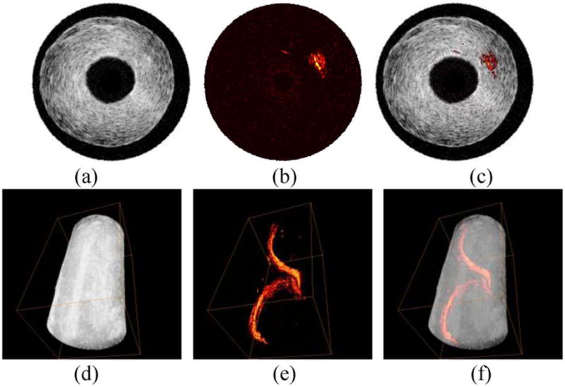
(a)–(c) Cross-sectional and (d)–(f) 3-D IVUS images [(a) and (d)], IVPA images [(b) and (e)], and combined IVUS/IVPA images [(c) and (f)] of a tissue mimicking phantom with a spiral inclusion embedded in the phantom wall. Adapted from [21].
IVUS images [see Fig. 2(a) and (d)] demonstrate the general structure of the phantom including lumen size and vessel wall thickness. However, the inclusion is not identifiable because of limited acoustic contrast between the inclusion and the vessel wall. In the IVPA images [see Fig. 2(b) and (e)], the inclusion is clearly visible, but no structural content of the vessel is shown. By combining the two images together [see Fig. 2(c) and (f)], the relative location of the inclusion in the phantom is displayed.
IV. Spectroscopic IVPA Imaging
The amplitude of the photoacoustic signal from the tissue is proportional to the product of optical absorption coefficient and the local laser fluence [22]. Therefore, at certain fluence, the contrast in photoacoustic imaging may reflect the optical absorption property of different types of tissues. Indeed, atherosclerotic plaques, blood, and other tissue constituents of the vessel wall not only have different magnitudes of optical absorption, but also wavelength-dependent optical absorption (see Fig. 3). Therefore, the wavelength-dependent optical absorption behavior of various tissue components is an independent parameter and may be used to identify the composition of arterial tissue.
Fig. 3.

Optical absorption spectra of potential tissues in atherosclerotic plaques [24], [25].
We investigated the potential of spectroscopic IVPA imaging to assess the composition of the plaques using ex vivo rabbit aorta samples [23]. IVPA images taken at multiple optical wavelengths were obtained using the IVUS/IVPA imaging system shown in Fig. 1(b). Both plaque-rich and healthy rabbit aortas were imaged from 680 to 900 nm wavelengths. The diseased aorta was obtained from a rabbit subjected to 0.15% cholesterol chow for ten months.
To analyze the spectral variation in the optical absorption of the plaques and tissue constituents, a simple method utilizing linear approximation of wavelength dependence of the optical absorption was employed. After compensation for the energy of each laser pulse, the first derivative of the optical absorption with respect to the wavelength was computed using the finite difference approach. Fig. 4 shows the spectroscopic IVPA images of the atherosclerotic and normal aorta computed using the finite differences of photoacoustic signals at 900 and 680 nm wavelength. The map of the plaque-rich aorta is fairly heterogeneous with positive and negative values of the first derivative. For example, three regions with distinctly different slopes are indicated by the arrows. In Fig. 4(a), region 1 contains positive slope due to an increase in light absorption with increase in the optical wavelength. The negative slope in region 3 indicates a decrease in the optical absorption coefficient, while the nearly constant values in region 2 suggests no significant change in optical absorption. Compared to the atherosclerotic vessel, the spectroscopic image of the control aorta shown in Fig. 4(b) is nearly homogeneous with regions largely containing slope values close to zero.
Fig. 4.
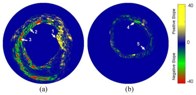
Spectroscopic (first derivative) IVPA images of: (a) the atherosclerotic and (b) control aorta calculated at 900 nm using a finite differences approach. The reference image for evaluating the first derivative was obtained at 680 nm. Adapted from [23].
For detailed analysis of the multiwavelength photoacoustic responses in the regions of interest, the relative energy (integral or area under the curve) of the original photoacoustic response was calculated. A 1-D trapezoidal numerical integration was evaluated for the magnitude of the IVPA responses in each of the 20 beams (28.8° azimuthal), covering a depth of 30 samples (225 μm radial). The energy of the photoacoustic response in various representative regions of atherosclerotic vessel and normal aorta was analyzed (see Fig. 5). Clearly, there are significant spatial and spectral variations in the energy of the photoacoustic signal within the plaque-rich vessel. The spatially averaged relative photoacoustic energy in the regions 1 and 3 shown in Fig. 5(a) corresponds to areas with positive and negative slopes, respectively. The energy of the photoacoustic signal in region 2 shown in Fig. 5(a) shows minimal variation, and is characteristically similar to the values obtained in regions 4 and 5 shown in Fig. 5(b).
Fig. 5.
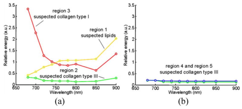
Variations in the relative energy of the photoacoustic responses with wavelength observed in: (a) atherosclerotic and (b) control aorta. The energy values were calculated from the regions marked 1, 2, 3, 4, and 5 in Fig. 4. Adapted from [23].
The spectroscopic IVPA images (see Fig. 4) and the energy variations of the photoacoustic responses (see Fig. 5) may be used to identify the constituents of the plaque and tissue. The optical absorption coefficient of fat (see Fig. 3) increases toward NIR range of wavelength with local maxima at around 920 and 1210 nm [25]–[27]. Therefore, to detect lipids, the major constituent of vulnerable plaques, the IVPA spectroscopic behavior of the tissue should be evaluated near these optical wavelength ranges where the differences in slopes between various tissues are largest. Our observation of positive slope values in the spectroscopic IVPA images (region 1 in Fig. 5) and the presence of lipids in the histology slides suggest that spectroscopic IVPA could possibly detect lipids in the plaque. The negligible changes of signal in region 2 and control aorta may indicate the location of thin fibrous structures of collagen type III. The regions of negative slope in the spectroscopic IVPA images (region 3 in Fig. 5) may correlate with the thickened fibrous deposits of collagen type I. This structural change in collagen is an important indicator that determines the stability of a plaque.
V. Molecular Imaging
Various biomarkers are present during the development of atherosclerotic lesions (see Fig. 6). The ability to detect and localize certain biomarkers in the atherosclerotic plaques would help to understand the pathology of atherosclerosis, facilitate the diagnosis of the disease while it is asymptomatic, identify the stage and vulnerability of plaques, and determine the proper therapeutic procedures. Many contrast agents with high optical absorption coefficients, such as gold nanoparticles (Au NPs) [28], can be used in photoacoustic imaging. These nanometer-sized contrast agents have their unique advantage in penetrating into the plaques embedded in the vessel. Contrast agent enhanced IVPA imaging can detect atherosclerotic lesions at a molecular and cellular level. Here, we focus on using Au NPs as contrast agents for IVPA imaging to identify macrophages in atherosclerotic plaques.
Fig. 6.

Biomarkers that are presented during the development of atherosclerotic lesion. Adapted from [29].
Macrophages play a crucial role in the development and vulnerability of plaques. Macrophages in atherosclerosis are derived from monocytes entering the intima layer of the vessel wall. Macrophages internalize low density lipoprotein (LDL) particles that enter into the vessel wall, and may later evolve to form the lipid pool in the plaques [29], [30]. Moreover, macrophages that infiltrate into the fibrous cap of plaques accelerate the progression of disease by releasing matrix metalloproteinases (MMPs). MMPs can weaken the fibrous cap and cause the plaque to be prone to rupture [31]. Because of the nonspecific uptake property of macrophages, Au NPs coated with methoxy-polyethylene glycolthiol (mPEG-SH) can be internalized by these cells.
Au NPs are a favorable contrast agent for photoacoustic imaging because of their high volumetric optical absorption coefficient and good biocompatibility [32]–[34]. The optical spectra of Au NPs can be tuned by changing the size and/or shape of the particles, thus providing flexibility for different imaging or therapeutic applications [35]. The surface of the NPs can be functionalized with various antibodies to target biomarkers of interest [36], [37]. One attractive property of Au NPs is surface plasmon resonance coupling that occurs if the distance between particles is in the range of diameter of the particles (i.e., NPs attached to the cell membrane or internalized into the cell). Plasmon resonance coupling results in the change of optical absorption spectrum [38]. This effect was previously used in photoacoustic imaging to detect anti-epidermal growth factor receptor (EGFR) antibody conjugated Au NPs interacting with EGFR positive cancer cells [39]. To test if plasmon resonance coupling can be utilized to identify macrophages loaded with Au NPs, murine macrophages (J774 A.1 cell line) were incubated with 50-nm-diameter spherical PEGylated Au NPs. The optical absorbance of the cells loaded with Au NPs and the Au NPs alone were measured by UV-vis spectrophotometer (see Fig. 7). Compared to the spectrum of Au NPs (green curve), the spectrum of cells loaded with NPs (red curve) is shifted around 20–30 nm to the longer wavelength. The peak of the spectrum was also broadened. The shift and broadening can be explained by the cumulative effect of plasmon resonance coupling of adjacent Au NPs after being internalized by macrophages.
Fig. 7.

Optical absorbance spectra of Au NPs and cells loaded with NPs. The spectra were normalized to their maximum absorbance within 450–800 nm wavelength.
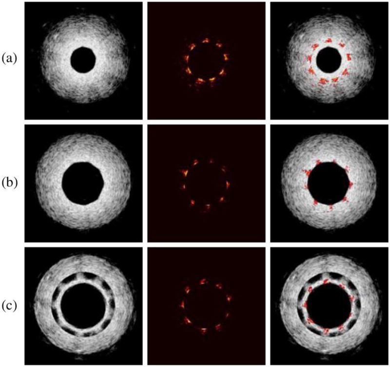
Macrophages loaded with particles were first imaged in a PVA phantom containing four compartments. The setup of the imaging system is shown in Fig. 1(b). Macrophages loaded with 50 nm Au NPs were resuspended in 10% gelatin gel (1 × 10⁴ –6 × 10⁴ NPs per cell with the total concentration of 2 × 10¹¹ per ml) and injected into one of the compartments in the phantom. Another compartment was injected with Au NPs uniformly mixed within gelatin gel (2 × 10¹¹ NPs per ml). These compartments simulated Au NPs internalized by macrophages in plaques and unbound Au NPs present in the blood stream or at the surface of the arterial wall. The remaining two compartments of the phantom were filled with either macrophages suspended in gelatin gel or gelatin gel alone. The structure of the phantom is depicted in Fig. 8(a). IVUS image [see Fig. 8(d)] clearly shows the cross-sectional structure of the phantom. As expected, ultrasound could not detect the presence of NPs. At 532 nm wavelength, high intensity photoacoustic signal [see Fig. 8(b)] was detected from the compartments containing NPs, thus indicating high optical absorption at this wavelength. By combining the spatially coregistered IVPA and IVUS images, the origin of the photoacoustic signal can be interpreted within the structure of the vessel phantom [see Fig. 8(c)]. If imaged at 680 nm wavelength [see Fig. 8(e) and (f)], only the compartment that contained cells loaded with NPs generated high photoacoustic signal. The difference in IVPA images at 532 and 680 nm wavelengths was because the absorption of individual Au NPs at 680 nm was much lower than that of cells loaded with NPs at higher wavelengths (see Fig. 7).
Fig. 8.

(a) Diagram and (d) IVUS image of the tissue mimicking vessel phantom with four compartments. The IVPA images of the same cross section of the phantom were taken at (b) 532 nm and (e) 680 nm wavelength. The combined IVUS and IVPA images of the phantom: (c) −532 and (f) −680 nm wavelength, indicating the origin of the photoacoustic responses in IVPA images. Adapted from [43].
The phantom experiment indicated that the optical absorption contrast created by Au NPs could be detected using the IVPA imaging system. Moreover, macrophages loaded with NPs could be differentiated from Au NPs alone by imaging at 680 nm wavelength. Thus, by imaging in the NIR wavelengths, it is possible to detect only macrophages labeled by NPs, but not the unbounded Au NPs, such as particles circulating in the blood. As a result, the IVPA imaging in the NIR range may be used to detect other pathology related targets in atherosclerosis, such as MMPs or ανβ3 integrin [40].
Furthermore, the detection limit of the IVPA imaging system on imaging macrophages at 680 nm was investigated using the same PVA phantoms with four compartments. Each compartment of the phantom was filled with different concentrations of particles per cell and/or cells per volume. The detection limit at 680 nm was 0.015 μmol/ml of gold in IVPA imaging [41]. This number is less than the detection limit of ferromagnetic NPs in MRI (within 0.089–0.893 μmol/ml of iron [42]).
To confirm that IVPA imaging may be used to image macrophages in atherosclerotic plaques, ex vivo tissue experiments were performed on a diseased rabbit aorta. A section of the aorta was extracted from a rabbit subjected to a high cholesterol diet for three months. Macrophages loaded with Au NPs were mixed with gelatin and injected into the vessel wall at three positions near the outer and inner boundaries of the aorta. Using IVUS/IVPA imaging system [see Fig. 1(b)], the sample was imaged at various wavelengths within 700–875 nm range.
The injected cells are notable in the cross-sectional IVUS image [see Fig. 9(a)]. The macrophages loaded with Au NPs do not backscatter ultrasound waves strongly and appear as hypoechoic regions (denoted by arrows). In IVPA image [see Fig. 9(b)] obtained using 700 nm wavelength, the injected areas produced high intensity photoacoustic signals. The result indicated that even in a highly optical scattering tissue such as diseased rabbit aorta, IVPA imaging can image macrophages loaded with Au NPs near the surface and embedded in the tissue. The wavelength dependence of the photoacoustic signal amplitudes from one injected area was normalized by the photoacoustic signal amplitude at 700 nm wavelength. The wavelength-dependent photoacoustic response decreases with the wavelength [see Fig. 9(c)]. This behavior is similar to the optical absorption spectra of aggregated Au NPs (see Fig. 7).
Fig. 9.

(a) IVUS image and (b) 700 nm IVPA image of a diseased rabbit aorta injected with macrophages loaded with Au NPs. Arrows indicate the locations of three injections of macrophages loaded with Au NPs. (c) Normalized photoacoustic signal at various wavelengths recorded from one of the locations. (d) Result of ICC analysis—the correlation coefficient higher than 0.75 is color coded and overlaid onto the IVUS image to identify the injection regions.
Intraclass correlation (ICC) analysis [45]—a measure of the strength of linear relationship between subjects belonging to the same class or subgroup, was applied to objectively identify the regions of injected macrophages. The multiwavelength photoacoustic signal from one of the injected areas [see Fig. 9(c)] was chosen as the correlation curve. The correlation between the photoacoustic responses from the tissue and the correlation curve was performed, and ICC coefficients were calculated [44]. Specifically, a correlation kernel size of 30 axial samples (110 μm) by 5 beams (6 degrees) was used in the ICC analysis. The computed correlation coefficient was assigned to the location corresponding to the middle of the kernel. The correlation analysis was performed at every position within the entire IVPA image, i.e., the kernel was moved with a step size of one sample or beam. At each position, the wavelength-dependent photoacoustic signal amplitude in the kernel was normalized by the signal amplitude at 700 nm wavelength and compared with the correlation curve. A correlation coefficient greater than 0.75 was color coded and overlaid on top of the IVUS image of the injected aorta [see Fig. 9(d)]. All three injected areas showed high correlation coefficients, which indicated that the injected areas had similar local optical absorption spectra as the aggregated Au NPs. The results also indicated that ICC analysis may be used to identify the location of aggregated Au NPs.
During the laser-based IVPA imaging, there are thermal effects associated with the absorption of laser energy by Au NPs. Although thermal effects can be used for selective destruction of cells [45], it is unwanted during the imaging procedure. Therefore, we conducted cell experiments to test cell viability after laser irradiation. A monolayer of macrophages loaded with Au NPs was irradiated at 680 nm wavelength with 50 laser pulses at 10 Hz pulse repetition frequency. After laser irradiation, cells were stained with fluorescein diacetate (FDA). The cells showed metabolic activity and membrane integrity after laser irradiation as high as 114 mJ/cm2 [41]. The laser fluence used in our phantom and ex vivo tissue experiments did not exceed 20 mJ/cm2. Therefore, the temperature elevation and other thermal effects during IVPA imaging are insignificant and do not cause any destructive effect [46]. However, in order to create a desired thermal therapeutic effect in the macrophages loaded with Au NPs, laser source pulses of longer duration or a continuous-wave laser may be utilized. In this way, after imaging the distribution of targeted NPs using IVPA system, the same light delivery system interfaced with a therapeutic light source could be used for selective laser therapy of atherosclerotic lesions.
VI. Imaging of Stents
Coronary stents are currently the most widely used coronary intervention for atherosclerosis in the United States. While the procedure is more than 95% successful [47], stents have brought along several unique issues including restenosis, hyperplasia, and stent drift. The ability to visualize stents both during the stenting procedure and during postsurgery follow-up is important in order to correctly assess the stent with respect to the plaques and vessel, and also identify its apposition within the vessel wall. Immediately following a stenting procedure, it is important to determine the relation of the stent struts to the vessel wall [48]. Ideally, the stent is deployed in contact with the lumen wall; however, malapposition can occur, resulting in the stent being detached from the wall. This can cause turbulent eddies to form in the vessel that can lead to thrombosis in the area of the stent. It is also important when monitoring the stent to determine how much restenosis has been formed around the stent struts. This distance must be determined to assess stent viability. Currently, the most common method for assessing stent position is X-ray coronary angiography/fluoroscopy [49]. However, this procedure is problematic due to its use of ionizing radiation and possible complications in using iodinated contrast agents. Furthermore, X-ray fluoroscopy can only depict a 2-D projection that can lead to an underestimation of the lumen diameter and the stent apposition within the lumen.
Other imaging modalities such as MRI and coherence tomography (CT) have problems with metallic susceptibility artifacts, which prevent the vessel lumen from being accurately visualized relative to the stent [47], [50]. The use of optical CT (OCT) directly competes with these disadvantages with a resolution of 10–20 μm, but has severe depth limitations, allowing only a penetration depth of about 2 mm [48], [51]. The presence of blood flowing through the vessel limits this depth even further, requiring clinicians to flush the vessel during the imaging procedure [52], [53]. Furthermore, the tissue behind the stent strut becomes hidden due to scattering shadows in OCT, which prevents complete diagnosis of the stent’s relation to the vessel lumen [52].
To counteract these disadvantages, we used the IVPA imaging system to image a clinical off-the-shelf stent (Cordis BX Velocity). The IVPA imaging has sufficient depth penetration, resolution, and contrast to visualize the stent and surrounding tissue. The imaging is tomographic, allowing 3-D reconstructions of the stent and vessel combined.
To test the feasibility of the IVPA system to image stents, a study was performed using a BX Velocity 5.0 mm stent embedded within the tissue-mimicking vessel. The cylindrical phantom was prepared using 8% PVA and 1% silica. The 10 mm outer diameter vessel had three different interior regions, where the inner diameter varied around the stent. These three regions were constructed so that the stent was embedded approximately 1.0 mm inside the vessel wall, deployed (adjacent to the vessel wall), and malapposed approximately 1.0 mm from the lumen wall. The malapposed region was creating a gap between the stent and the vessel wall. However, due to the molding process during phantom fabrication, the stent itself was covered with a thin film of PVA.
Imaging of the vessel and stent was performed using the prototype IVUS/IVPA benchtop system similar to the setup shown in Fig. 1(b), where, instead of an air beam, laser irradiated the vessel from the outside using an optical fiber delivering 800 nm wavelength light. This wavelength was chosen for sufficient depth penetration. For pullback-based 3-D imaging, a 1-D axis was placed under the water cuvette to move the sample along its longitudinal axis.
The cross-sectional ultrasound, photoacoustic, and combined images of the vessel phantom with the stent are shown in Fig. 10. With the ultrasound signal displayed at 40 dB, the photoacoustic images at 15 dB show high contrast between the stent and the background.
Fig. 10.
(Left column) IVUS, (middle column) IVPA, and (right column) combined IVUS/IVPA images from the three different stent regions in the vessel. (a) Stent embedded within the vessel. (b) Stent adjacent to lumen wall. (c) Stent detached from lumen wall. Due to the fabrication of this section of the PVA phantom, a thin layer of PVA was formed on the surface of the stent. This PVA film is the source of the additional inner ultrasound ring in (c), where the stent is located. Adapted from [54].
Indeed, photoacoustic signal from the stent is high due to the high optical absorption of metal struts compared to the vessel that has little photoacoustic response at this wavelength. This allowed high contrast of the stent to the background tissue. The ultrasound image visualized the complete vessel including the structure and thickness of the vessel wall. Therefore, the location of the stent (IVPA image) was given in relation to the vessel (IVUS image). By scanning along the length of the vessel, the varying radial distance between the stent and the lumen wall could be assessed. In the region where the stent was embedded within the vessel [see Fig. 10(a)], the stent struts were measured embedded 0.7–1.0 mm within the vessel wall. In the region where the stent was merely adjacent to the vessel wall [see Fig. 10(b)], the image gave good qualitative agreement in visualizing the correct position of the stent to the vessel. The malapposed section was also quantitatively measured and showed that the stent was malapposed away from the lumen wall by 0.8–1.1 mm [see Fig. 10(c)].
By combining a set of 80 cross-sectional images, a 3-D image of the entire vessel wall and stent was reconstructed (see Fig. 11). The structure of the stent was clearly seen in the context of the vessel structure. The transparency (alpha value) of the ultrasound image was modified such that only the photoacoustic signal could be seen, leaving only the structure of the stent [see Fig. 11(b)]. The shape and position of the stent within the vessel is easily assessed [see Fig. 11(c)]. The photoacoustic image also allowed the inner diameter of the stent to be correctly measured at 5.0 mm, the manufacturer reported size of the stent.
Fig. 11.

3-D reconstructed (a) IVUS, (b) IVPA, and (c) combined images of trisectional phantom. Individual cross sections can show the position of the stent within the vessel. Photoacoustic signal alone can assess the shape of the stent in order to determine the condition of the stent. Adapted from [54].
Fig. 12 demonstrated that a stent deployed into an excised sample of rabbit aorta could also be visualized in the IVPA image. Even though the tissue was irradiated externally by the laser, sufficient laser fluence penetrated the vessel wall to generate photoacoustic signals with enough contrast from the stent. Thus, IVPA imaging may be able to image stents embedded deep inside the arterial wall.
Fig. 12.

Reconstructed (a) IVUS, (b) IVPA, and (c) combined images of a stent deployed within an excised section of an atherosclerotic rabbit aorta. Stent is visible as adjacent to lumen wall.
Since in vivo IVUS/IVPA imaging may occur in the presence of optically attenuating luminal blood, we also imaged the samples in an optical scattering environment created with a mixture of low fat milk and water. The optical fiber delivering the light to the vessel was placed 0.5 cm away from the surface of the vessel. Although the photoacoustic signal intensity showed a reduction in the peak signal intensity of the stent struts due to the light attenuation of milk, the quality of the IVPA image was reduced insignificantly.
Coronary artery stents are well visualized using combined IVUS/IVPA imaging. Ultrasound imaging provides useful structural information of the vessel wall. Photoacoustic imaging utilizes the differential optical absorption of laser energy and offers high optical contrast in viewing the metal stent relative to the surrounding vessel. In the combined IVPA/IVUS images, the full structure of the phantom is visible and not obscured behind the stent struts, thus allowing one to see the apposition of the stent within the vessel wall, regardless of where the stent was located.
The use of IVUS/IVPA imaging to image stents is a natural progression as stents are commonly used to treat blood vessels that have narrowed due to atherosclerosis. Recent studies have shown that stent positioning can drift over time, bringing the need to detect stent location with respect to the site of atherosclerosis while analyzing the progression of plaque vulnerability also. Our study clearly shows that IVUS/IVPA imaging is a promising modality to image stents in vivo.
VII. Integrated Imaging Catheter
In the laboratory prototype of the IVUS/IVPA imaging system [see Fig. 1(b)], the ultrasound transducer was positioned inside the lumen, while the light was delivered externally. For in vivo IVUS/IVPA imaging, the laser irradiation should be delivered inside the lumen. Therefore, the combined IVUS/IVPA imaging requires an integrated imaging catheter consisting of an ultrasound transducer and a light delivery system. Others have reported the design of an endoscopic photoacoustic probe with ultrasound transducer and fiber optics [55], [56]. Here, we introduce two designs of integrated catheters for combined IVUS/IVPA imaging using IVUS catheter and fiber optics.
Two prototypes of the integrated IVUS/IVPA imaging catheters were built based on a single-element ultrasound transducer coupled with two different types of light delivery systems. One prototype used a side fire fiber while the second design utilized microoptics. In both designs, the purpose of the light delivery system is to direct the optical beam approximately 90° relative to the longitudinal axis of the optical fiber. In this way, the laser light will irradiate the vessel wall within the ultrasound imaging plane.
The operation of the light delivery system in the side fire fiber-based IVUS/IVPA imaging catheter is based on the effect of total internal reflection (TIR) that takes place when the distal end of the fiber is polished at a certain angle. The light distribution near the distal end of the fiber, the microphotograph, and the diagram of the integrated IVUS/IVPA imaging catheter are shown in Fig. 13. Because of the nonzero numerical aperture (NA) of the fiber, laser radiation can propagate inside the fiber within certain cone [shown as gray region in Fig. 13(a)] with a full cone angle of 2α. If β is a polishing angle of the fiber, then the TIR effect appears when this angle is less than
Fig. 13.

(a) Schematic diagram of the light distribution near the distal end of the optical fiber. (b) Photograph of the distal end of the integrated IVUS/IVPA side fire fiber-based imaging catheter that utilizes the TIR effect. (c) Diagram of the integrated IVUS/IVPA imaging catheter showing the alignment between ultrasound and light beams. Adapted from [57].
where nmed, ncore, and ncl are the refractive indexes of the medium around the fiber, fiber’s core, and cladding, respectively. The TIR effect increases for smaller angles and reaches 100% when the polishing angle β is
If β2 < β < β1, a limited fraction of the light will be redirected by the TIR effect and the remaining light will not be utilized in IVPA imaging. To achieve reasonable values for both β1 and β2 angles, a medium with refractive index different from that of water is needed. Therefore, the distal end of the fiber was sealed with a glass cup containing air [see Fig. 13(b)]. In such configuration, light can be completely redirected by TIR effect with a polishing angle of about 62°. Partial redirection will take place with a polishing angle up to about 125°.
The side fire fiber-based light delivery system was coupled with a single-element IVUS imaging catheter as shown in Fig. 13(c). The IVUS transducer and light delivery system were aligned to insure the best overlap between the ultrasound and laser beams. This prototype of the integrated catheter was used to obtain the experimental results shown in Fig. 2 and Fig. 16(a) and (b).
Fig. 16.
[(a) and (c)] Ultrasound and [(b) and (d)] photoacoustic images of the point-target phantom obtained using the side fire fiber-based [(a) and (b)] and the mirror-based [(c) and (d)] combined IVUS/IVPA imaging catheters. Adapted from [57].
In the second prototype of the integrated IVUS/IVPA imaging catheter shown in Fig. 14, the distal end of the optical fiber was polished perpendicularly to optical axes and flat (i.e., at the 90° angle), and a micromirror was used to redirect the light [see Fig. 14(a)]. The mirror was attached to the fiber using a custom-made brass fixture. The IVUS transducer was fixed to the optical fiber with the ultrasound element facing away from the fiber. The angle between the axis of the optical fiber and the mirror was chosen to achieve the maximum overlap between the light and ultrasound beams [see Fig. 14(b)] while avoiding any possible direct interaction of light with the transducer.
Fig. 14.

Prototype of the microoptics mirror-based combined IVUS/IVPA mirror-based imaging catheter. (a) Photograph of distal end of the IVUS/IVPA imaging catheter. (b) Diagram of the catheter showing an alignment of the ultrasound and light beams. Adapted from [57].
Both prototypes of the integrated IVUS/IVPA imaging catheters were tested using point target and tissue-mimicking phantoms. The diagram of a point-target phantom is shown in Fig. 15. The phantom consisted of 12 point targets that should be visible in both ultrasound and photoacoustic imaging. The targets were positioned along the spiral trajectory such that 11 targets, positioned at different angles, were 4–9 mm away from the center of the phantom in 0.5 mm increments. The last, 12th point target was positioned 10 mm away from the center of the phantom and behind the first target. These point targets were embedded into a tissue-mimicking environment made out of 10% gelatin. To mimic acoustic properties of tissue, 0.5% silica particles with average sizes of 40 μm were added.
Fig. 15.
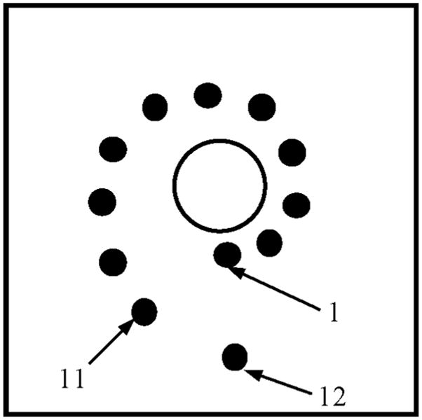
Diagram of phantom with point targets used to evaluate the performance of the integrated IVUS/IVPA imaging catheters.
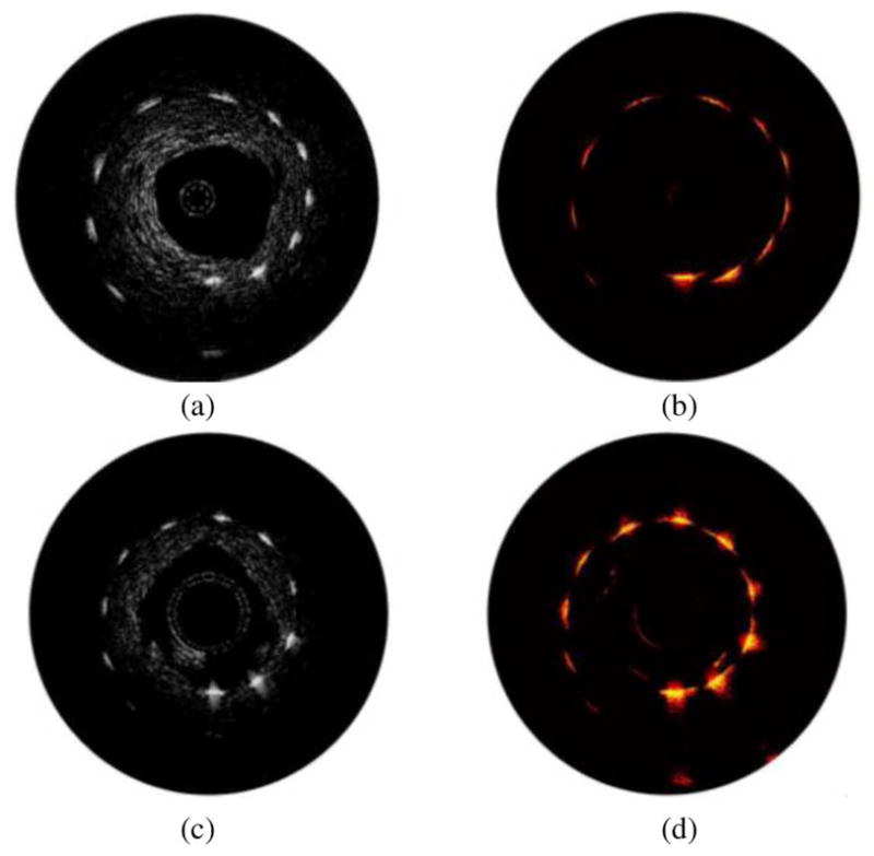
The ultrasound images (30 dB display dynamic range) and photoacoustic images (25 dB display dynamic range) of the point-target phantom are shown in Fig. 16. The images shown in Fig. 16(a) and (b) were obtained by the side fire fiber-based catheter, while the images obtained using mirror-based catheter are shown in Fig. 16(c) and (d). Ultrasound B-scans shown in Fig. 16(a) and (c) outline the structure of the phantom. The signal from the targets slightly decreased with depth due to ultrasound beam divergence and the attenuation of the high-frequency (40 MHz) ultrasound in the tissue-mimicking environment. The differences between the ultrasound images are attributed to slightly different planes imaged with each imaging catheter and different characteristics of the IVUS transducers used in the experiments.
The IVPA images shown in Fig. 16(b) and (d) demonstrate a decrease of the photoacoustic signal strength with depth. Because of the light reflection at the water–gelatin interface and the scattering from silica particles in the phantom, the laser fluence decreases with increased imaging depth. As a result, the target located furthest away from the catheter becomes invisible due to limited light illumination.
For clinical applications of IVUS/IVPA imaging, the integrated catheter should be able to freely travel along the vessel. To retain flexibility, the diameter of the optical fiber is limited to a few hundreds of micrometers. To increase the efficiency of the light delivery system without affecting the flexibility of the catheter, a bundle of optical fibers may be used instead of a single optical fiber. One possible design of such fiber bundle-based light delivery system is shown in Fig. 17. The integrated IVUS/IVPA imaging catheter consists of a single-element, mechanically rotated IVUS imaging transducer. The light delivery system is based on a set of stationary, small diameter optical fibers surrounding the IVUS catheter. A laser beam emitted from one of the fiber is shown in Fig. 17. During IVPA imaging, laser beams emitted from several fibers will overlap to achieve high laser fluence. In this design, a port for fiber in the fiber bundle may be replaced by a guide wire that is critical for guiding the integrated catheter along the artery.
Fig. 17.
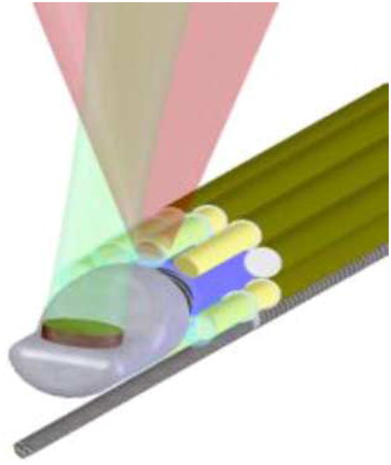
Combined IVUS/IVPA imaging catheter based on a single-element mechanically rotating IVUS transducer and light delivery system consisting of bundle of optical fibers surrounding the ultrasound transducer.
VIII. Conclusion
IVPA imaging provides a way to visualize the optical absorption property of atherosclerotic lesions. In this paper, we reviewed various attractive applications for combined IVUS/IVPA imaging. Based on the unique optical absorption spectra of various tissue types, IVPA imaging may identify the tissue composition in the blood vessel wall. By introducing functionalized Au NPs as contrast agent, IVPA imaging may be used for cellular imaging (i.e., macrophages) or molecular imaging (i.e., adhesion molecules, selectins, and integrins). IVPA imaging may also be used to guide the placement of coronary stents and monitor the deployed stents within the content of the surrounding tissue. Lastly, various designs of the integrated catheter for combined IVUS/IVPA imaging were discussed.
Acknowledgments
The authors are grateful to J. H. Amirian from the University of Texas Health Science Center Houston for providing the excised samples of rabbit aorta. They also would like to acknowledge the in-kind support from Boston Scientific, Inc.
This work was supported in part by the American Heart Association under Grant 0655033Y and by the National Institutes of Health under Grant HL084076, HL096981.
Biographies
 Bo Wang (M’06) received the B.S. and M.S. degrees in control science and engineering from Harbin Institute of Technology, Harbin, China, in 2004 and 2006, respectively. She is currently working toward the Ph.D. degree in the Department of Biomedical Engineering, University of Texas, Austin.
In 2006, she joined the Ultrasound Imaging and Therapeutics Research Laboratory, University of Texas. Her research interests include the use of combined intravascular photoacoustic and ultrasound imaging to detect and differentiate vulnerable plaques, and the use of gold nanoparticles as a contrast agent for intravascular photoacoustic imaging.
Miss Wang was the recipient of the Best Student Paper Award at the 2008 IEEE Ultrasonics Symposium. She was also the recipient of the University of Texas Continuing Fellowship Award for the year 2009–2010.
 Jimmy L. Su received the B.S. degree in biomedical engineering with a concentration in electrical engineering from The Johns Hopkins University, Baltimore, MD, in 2002, and the M.S. degree in biomedical engineering in 2006 from the University of Texas, Austin, where he is currently working toward the Ph.D. degree in the Ultrasound Imaging and Therapeutics Research Laboratory, Department of Biomedical Engineering.
After moving to Austin, TX, he worked for BAE Systems, designing biological detection devices. He was involved in computational models of human walking to determine a quantitative measurement of walking stability. His current research interests include the use of ultrasound and photoacoustic imaging to visualize metal structures implanted within the body.
 Andrei B. Karpiouk (M’07) received the B.S, M.S., and Ph.D. degrees in laser physics from Moscow Engineering Physics Institute (Technical University), Moscow, Russia, in 1992, 1994, and 2002, respectively.
From 2003 to 2004, he was a Postdoctoral Fellow in the Laser Center, University of Texas Medical Branch, Galveston, where he conducted research on combined photoacoustic and ultrasound imaging for early cancer detection. From 2004 to 2008, he was with the University of Texas, Austin, as a Research Assistant, where he was engaged in research of laser–tissue interaction processes and development of new methods for ultrasound-based medical imaging and sensing, and is currently a Research Engineering/Scientist Associate III in the Department of Biomedical Engineering. His research interests include combined medical imaging and sensing, biomedical engineering, research of laser–tissue interaction processes, and measurements of biomechanical properties of soft tissues.
 Konstantin V. Sokolov received the Diploma degree in physics from Moscow Engineering-Physics Institute, Moscow, Russia, in 1987, and the Ph.D. degree in biophysics from Moscow State University, Moscow, in 1992.
He was involved in biomedical applications of surface-enhanced Raman spectroscopy. He was a Postdoctoral Fellow at the Institute of Bioorganic Chemistry Russian Academy of Science, Moscow, Russia; the University of Reims, Reims, France; and the Department of Chemistry, Iowa State University, Ames, IA, where he carried out research in the field of optical spectroscopy of biomolecules and bioanalytical chemistry. Currently, he is an Associate Professor in the Departments of Biomedical Engineering and Imaging Physics, University of Texas M. D. Anderson Cancer Center, Houston. He also has a joined appointment in the Department of Biomedical Engineering, University of Texas, Austin. His research interests include the development of novel applications of nanoparticles for functional imaging, ultra-sensitive detection of biomolecules, and developing nanomaterials that enable improved delivery of molecular therapeutics with site-specific release and activation using an external stimulus.
 Richard W. Smalling received the B.S. degree in aerospace engineering, the M.S. degree in biomedical engineering, and the M.D. and Ph.D. degrees from the University of Texas, Austin.
He is currently the Jay Brent Sterling Professor of cardiovascular medicine and the Director of Interventional Cardiovascular Medicine, Division of Cardiology, University of Texas Medical School, Houston, and the Memorial Hermann Heart and Vascular Institute, Houston. He was with the University of California at San Diego, La Jolla, CA, where he was a Residency Trainee and a Cardiology Research Fellow. Board certied in internal medicine, cardiovascular medicine, and interventional cardiology, he is the author or coauthor of more than 2000 peer reviewed articles and more than a dozen textbook chapters. He is an active investigator in clinical cardiology in the areas of thrombolysis and facilitated percutaneous interventions for acute myocardial infarctions, new interventional devices, and percutaneous left ventricular assist devices. In addition to his clinical duties as an interventional cardiologist, he has an active animal physiology laboratory engaged in evaluation of mechanisms for prevention of reperfusion injury, as well as new device development for coronary interventions and left ventricular assist.
Dr. Smalling is on the Editorial Board of various cardiovascular journals.
 Stanislav Y. Emelianov (M’94) received the B.S. and M.S. degrees in physics and acoustics from Moscow State University, Moscow, Russia, in 1986 and 1989, respectively, and the Ph.D. degree in physics from Moscow State University, and the Institute of Mathematical Problems of Biology, Russian Academy of Sciences, Moscow, in 1993.
In 1989, he joined the Institute of Mathematical Problems of Biology, where he was engaged in both mathematical modeling of soft tissue biomechanics and experimental studies of noninvasive visualization of tissue mechanical properties. He was with the University of Michigan, Ann Arbor, as a Postdoctoral Fellow in the Bioengineering Program, and the Electrical Engineering and Computer Science Department, where he was a Research Scientist in the Biomedical Ultrasonics Laboratory from 1996 to 2002, and was involved primarily in the theoretical and practical aspects of elasticity imaging. Since 2002, he has been with the University of Texas, Austin, where he formed the Ultrasound Imaging and Therapeutics Research Laboratory, and is currently an Associate Professor in the Department of Biomedical Engineering. His research interests include medical imaging for therapeutics and diagnostic applications including molecular/cellular imaging, hybrid nanoparticles acting as imaging contrast and therapeutic agents, functional imaging, photoacoustic imaging, elasticity imaging, image-guided therapy, and ultrasound biomicroscopy.
Footnotes
Color versions of one or more of the figures in this paper are available online at http://ieeexplore.ieee.org.
Contributor Information
Bo Wang, Email: wangbo@mail.utexas.edu, Department of Biomedical Engineering, University of Texas at Austin, Austin, TX 78712 USA.
Jimmy L. Su, Email: immysu@mail.utexas.edu, Department of Biomedical Engineering, University of Texas at Austin, Austin, TX 78712 USA
Andrei B. Karpiouk, Email: andrei.karpiouk@engr.utexas.edu, Department of Biomedical Engineering, University of Texas at Austin, Austin, TX 78712 USA.
Konstantin V. Sokolov, Email: kostia@mail.utexas.edu, Department of Biomedical Engineering, University of Texas at Austin, Austin, TX 78712 USA, and also with the Department of Imaging Physics, University of Texas M.D. Anderson Cancer Center, Houston, TX 77030 USA
Richard W. Smalling, Email: richard.w.smalling@uth.tmc.edu, Division of Cardiology, University of Texas Health Science Center, Houston, TX 77030 USA, and also with the Memorial Hermann Heart and Vascular Institute, Houston, TX 77024 USA
Stanislav Y. Emelianov, Email: emelian@mail.utexas.edu, Department of Biomedical Engineering, University of Texas at Austin, Austin, TX 78712 USA.
References
- 1.Rosamond W, Flegal K, Furie K, Go A, Greenlund K, Haase N, Hailpern SM, Ho M, Howard V, Kissela B. Heart disease and stroke statistics–2008 update: A report from the american heart association statistics committee and stroke statistics subcommittee. Circulation. 2008;117:e25–e146. doi: 10.1161/CIRCULATIONAHA.107.187998. [DOI] [PubMed] [Google Scholar]
- 2.Naghavi M, Libby P, Falk E, Casscells SW, Litovsky S, Rumberger J, Badimon JJ, Stefanadis C, Moreno P, Pasterkamp G, Fayad Z, Stone PH, Waxman S, Raggi P, Madjid M, Zarrabi A, Burke A, Yuan C, Fitzgerald PJ, Siscovick DS, de Korte CL, Aikawa M, Airaksinen KEJ, Assmann G, Becker CR, Chesebro JH, Farb A, Galis ZS, Jackson C, Jang I-K, Koenig W, Lodder RA, March K, Demirovic J, Navab M, Priori SG, Rekhter MD, Bahr R, Grundy SM, Mehran R, Colombo A, Boerwinkle E, Ballantyne C, Insull W, Jr, Schwartz RS, Vogel R, Serruys PW, Hansson GK, Faxon DP, Kaul S, Drexler H, Greenland P, Muller JE, Virmani R, Ridker PM, Zipes DP, Shah PK, Willerson JT. From vulnerable plaque to vulnerable patient: A call for new definitions and risk assessment strategies: Part I. Circulation. 2003;108:1664–1672. doi: 10.1161/01.CIR.0000087480.94275.97. [DOI] [PubMed] [Google Scholar]
- 3.Emelianov SY, Aglyamov SR, Shah J, Sethuraman S, Scott WG, Schmitt R, Motamedi M, Karpiouk A, Oraevsky A. Combined ultrasound, optoacoustic and elasticity imaging. Proc 2004 SPIE Photon West Symp, Photons Plus Ultrasound: Imag Sens. 5320:101–112. [Google Scholar]
- 4.Beard PC, Mills TN. Characterization of post mortem arterial tissue using time-resolved photoacoustic spectroscopy at 436, 461 and 532 nm. Phys Med Biol. 1997;42:177–198. doi: 10.1088/0031-9155/42/1/012. [DOI] [PubMed] [Google Scholar]
- 5.Oraevsky AA, Esenaliev RO, Jacques SL, Tittel FK. Laser optoacoustic tomography for medical diagnostics: Principles. Proc 1996 SPIE Photon West Symp, Photons Plus Ultrasound: Imag Sens. 2676:22–31. [Google Scholar]
- 6.Oraevsky AA, Karabutov AA. Optoacoustic Tomography. PM125. Boca Raton, FL: CRC Press; 2003. [Google Scholar]
- 7.Ku G, Wang LV. Scanning thermoacoustic tomography in biological tissue. Med Phys. 2000;27:1195–1202. doi: 10.1118/1.598984. [DOI] [PubMed] [Google Scholar]
- 8.Kruger RA, Reinecke DR, Kruger GA. Thermoacoustic computed tomography-technical considerations. Med Phys. 1999;26:1832–1837. doi: 10.1118/1.598688. [DOI] [PubMed] [Google Scholar]
- 9.Oraevsky AA, Jacques SL, Tittel FK. Measurement of tissue optical properties by time-resolved detection of laser-induced transient stress. Appl Opt. 1997;36:402–415. doi: 10.1364/ao.36.000402. [DOI] [PubMed] [Google Scholar]
- 10.Oraevsky AA, Karabutov AA. Optoacoustic Tomography. Vol. 34. Boca Raton, FL: CRC Press; 2003. [Google Scholar]
- 11.Wang LV. Tutorial on photoacoustic microscopy and computed tomography. IEEE J Sel Topics Quantum. 2008 Jan.–Feb;14(1):171–179. [Google Scholar]
- 12.Sethuraman S, Aglyamov SR, Amirian JH, Smalling RW, Emelianov SY. Intravascular photoacoustic imaging using an IVUS imaging catheter. IEEE Trans Ultrason, Ferroelectr, Freq Control. 2007 May;54(5):978–986. doi: 10.1109/tuffc.2007.343. [DOI] [PubMed] [Google Scholar]
- 13.Nissen SE, Yock P. Intravascular ultrasound: Novel pathophysiological insights and current clinical applications. Circulation. 2001;103:604–616. doi: 10.1161/01.cir.103.4.604. [DOI] [PubMed] [Google Scholar]
- 14.Fitzgerald PJ, Yock PG. Mechanisms and outcomes of angioplasty and atherectomy assessed by intravascular ultrasound imaging. J Clin Ultrasound. 1993;21:579–588. doi: 10.1002/jcu.1870210905. [DOI] [PubMed] [Google Scholar]
- 15.Franzen D, Sechtem U, Hopp HW. Comparison of angioscopic, intravascular ultrasonic, and angiographic detection of thrombus in coronary stenosis. Amer J Cardiol. 1998;82:1273–1275. doi: 10.1016/s0002-9149(98)00616-x. [DOI] [PubMed] [Google Scholar]
- 16.Bridal SL, Fornes P, Bruneval P, Berger G. Correlation of ultrasonic attenuation (30 to 50 MHz and constituents of atherosclerotic plaque. Ultrasound Med Biol. 1997;23:691–703. doi: 10.1016/s0301-5629(97)00072-0. [DOI] [PubMed] [Google Scholar]
- 17.de Korte CL, Pasterkamp G, van Der Steen AF, Woutman HA, Bom N. Characterization of plaque components with intravascular ultrasound elastography in human femoral and coronary arteries in vitro. Circulation. 2000;102:617–623. doi: 10.1161/01.cir.102.6.617. [DOI] [PubMed] [Google Scholar]
- 18.Feinstein SB. Contrast ultrasound imaging of the carotid artery vasa vasorum and atherosclerotic plaque neovascularization. J Amer Coll Cardiol. 2006;48:236–243. doi: 10.1016/j.jacc.2006.02.068. [DOI] [PubMed] [Google Scholar]
- 19.Karpiouk AB, Aglyamov SR, Mallidi S, Shah J, Scott WG, Rubin J, Emelianov SY. Combined ultrasound and photoacoustic imaging to detect and stage deep vein thrombosis: Phantom and ex vivo studies. J Biomed Opt. 2008;13:054061. doi: 10.1117/1.2992175. [DOI] [PubMed] [Google Scholar]
- 20.Allen TJ, Beard PC. Photoacoustic characterisation of vascular tissue at NIR wavelengths. Proc Photons Plus Ultrasound, Imag Sens. 2009:71770A-1–71770A-9. [Google Scholar]
- 21.Wang B, Karpiouk AB, Emelianov SY. Design of catheter for combined intravascular photoacoustic and ultrasound imaging. Proc 2008 IEEE Ultrason Symp. :1150–1153. [Google Scholar]
- 22.Gusev V, Karabutov A. Laser Optoacoustics. New York: AIP Press; 1991. [Google Scholar]
- 23.Sethuraman S, Amirian JH, Litovsky SH, Smalling RW, Emelianov SY. Spectroscopic intravascular photoacoustic imaging to differentiate atherosclerotic plaques. Opt Exp. 2008;16:3362–3367. doi: 10.1364/oe.16.003362. [DOI] [PubMed] [Google Scholar]
- 24.Anderson RR, Farinelli W, Laubach H, Manstein D, Yaroslavsky AN, Gubeli J, III, Jordan K, Neil GR, Shinn M, Chandler W. Selective photothermolysis of lipid-rich tissues: A free electron laser study. Lasers Surg Med. 2006;38:913–919. doi: 10.1002/lsm.20393. [DOI] [PubMed] [Google Scholar]
- 25.Prahl SA. Optical properties spectra compiled by Scott Prahl [Online] 2001 Available: http://omlc.ogi.edu/spectra/
- 26.van Veen RLP, Sterenborg HJCM, Pifferi A, Torricelli A, Cubeddu R. Determination of visible near-IR absorption coefficients of mammalian fat using time- and spatially resolved diffuse reflectance and transmission spectroscopy. J Biomed Opt. 2005;10:054004-1–054004-6. doi: 10.1117/1.2085149. [DOI] [PubMed] [Google Scholar]
- 27.Tromberg B, Shah N, Lanning R, Cerussi A, Espinoza J, Pham T, Svaasand L, Butler J. Non-invasive in vivo characterization of breast tumors using photon migration spectroscopy. Neoplasia. 2000;2:26–40. doi: 10.1038/sj.neo.7900082. [DOI] [PMC free article] [PubMed] [Google Scholar]
- 28.Conjusteau A, Ermilov SA, Lapotko D, Liao H, Hafner J, Eghtedari M, Motamedi M, Kotov N, Oraevsky AA. Metallic nanoparticles as optoacoustic contrast agents for medical imaging. Proc SPIE. 2006;6086:1605–7422. [Google Scholar]
- 29.Sanz J, Fayad ZA. Imaging of atherosclerotic cardiovascular disease. Nature. 2008;451:953–957. doi: 10.1038/nature06803. [DOI] [PubMed] [Google Scholar]
- 30.Falk E. Pathogenesis of atherosclerosis. J Amer Coll Cardiol. 2006;47:C7–C12. doi: 10.1016/j.jacc.2005.09.068. [DOI] [PubMed] [Google Scholar]
- 31.Galis ZS, Sukhova GK, Kranzhofer R, Clark S, Libby P. Macrophage foam cells from experimental atheroma constitutively produce matrix-degrading proteinases. Proc Nat Acad Sci USA. 1995:402–406. doi: 10.1073/pnas.92.2.402. [DOI] [PMC free article] [PubMed] [Google Scholar]
- 32.Eghtedari M, Oraevsky A, Copland JA, Kotov NA, Conjusteau A, Motamedi M. High sensitivity of in vivo detection of gold nanorods using a laser optoacoustic imaging system. Nano Lett. 2007;7:1914–1918. doi: 10.1021/nl070557d. [DOI] [PubMed] [Google Scholar]
- 33.Li PC, Wei CW, Liao CK, Chen CD, Pao KC, Wang CR, Wu YN, Shieh DB. Photoacoustic imaging of multiple targets using gold nanorods. IEEE Trans Ultrason, Ferroelectr, Freq Control. 2007 Aug;54(8):1642–1647. doi: 10.1109/tuffc.2007.435. [DOI] [PubMed] [Google Scholar]
- 34.Mallidi S, Larson T, Aaron J, Sokolov K, Emelianov S. Molecular specific optoacoustic imaging with plasmonic nanoparticles. Opt Exp. 2007;15:6583–6588. doi: 10.1364/oe.15.006583. [DOI] [PubMed] [Google Scholar]
- 35.Link S, Mohamed MB, El-Sayed MA. Simulation of the optical absorption spectra of gold nanorods as a function of their aspect ratio and the effect of the medium dielectric constant. J Phys Chem B. 1999;103:3073–3077. [Google Scholar]
- 36.Aaron JS, Oh J, Larson TA, Kumar S, Milner TE, Sokolov KV. Increased optical contrast in imaging of epidermal growth factor receptor using magnetically actuated hybrid gold/iron oxide nanoparticles. Opt Exp. 2006;14:12930–12943. doi: 10.1364/oe.14.012930. [DOI] [PubMed] [Google Scholar]
- 37.Larson TA, Bankson J, Aaron J, Sokolov K. Hybrid plasmonic magnetic nanoparticles as molecular specific agents for MRI/optical imaging and photothermal therapy of cancer cells. Nanotechnology. 2007;18:325101-1–325101-8. [Google Scholar]
- 38.Aaron J, Nitin N, Travis K, Kumar S, Collier T, Park SY, Jose-Yacaman M, Coghlan L, Follen M, Richards-Kortum R, Sokolov K. Plasmon resonance coupling of metal nanoparticles for molecular imaging of carcinogenesis in vivo. J Biomed Opt. 2007;12:034007-1–034007-11. doi: 10.1117/1.2737351. [DOI] [PubMed] [Google Scholar]
- 39.Mallidi S, Larson T, Aaron J, Sokolov K, Emelianov S. Molecular specific optoacoustic imaging with plasmonic nanoparticles. Opt Exp. 2007;15:6583–6588. doi: 10.1364/oe.15.006583. [DOI] [PubMed] [Google Scholar]
- 40.Hoshiga M, Alpers CE, Smith LL, Giachelli CM, Schwartz SM. αvβ3 integrin expression in normal and atherosclerotic artery. Circulation Res. 1995;77:1129–1135. doi: 10.1161/01.res.77.6.1129. [DOI] [PubMed] [Google Scholar]
- 41.Wang B, Yantsen E, Sokolov K, Emelianov S. High sensitivity intravascular photoacoustic imaging of macrophages. Proc SPIE. 2009:71770V-1–71770V-6. [Google Scholar]
- 42.Pardoe H, Chua-anusorn W, StPierre TG, Dobson J. Detection limits for ferrimagnetic particle concentrations using magnetic resonance imaging based proton transverse relaxation rate measurements. Phys Med Biol. 2003;48:N89–N95. doi: 10.1088/0031-9155/48/6/401. [DOI] [PubMed] [Google Scholar]
- 43.Wang B, Yantsen E, Larson T, Karpiouk AB, Sethuraman S, Su JL, Sokolov K, Emelianov SY. Plasmonic intravascular photoacoustic imaging for detection of macrophages in atherosclerotic plaques. Nano Lett. 2009;9:2212–2217. doi: 10.1021/nl801852e. [DOI] [PubMed] [Google Scholar]
- 44.Indrayan A, Sarmukaddam SB. Medical Biostatistics. Boca Raton, FL: CRC Press; 2001. [Google Scholar]
- 45.Huang X, Jain PK, El-Sayed IH, El-Sayed MA. Plasmonic photothermal therapy (PPTT) using gold nanoparticles. Lasers Med Sci. 2008;23:217–228. doi: 10.1007/s10103-007-0470-x. [DOI] [PubMed] [Google Scholar]
- 46.Sethuraman S, Aglyamov S, Smalling R, Emelianov S. Remote temperature estimation in intravascular photoacoustic imaging. Ultrasound Med Biol. 2008;34:299–308. doi: 10.1016/j.ultrasmedbio.2007.07.021. [DOI] [PMC free article] [PubMed] [Google Scholar]
- 47.Maintz D, Botnar RM, Fischbach R, Heindel W, Manning WJ, Stuber M. Coronary magnetic resonance angiography for assessment of the stent lumen: A phantom study. J Cardiovasc Magn Reson. 2002;4:359–367. doi: 10.1081/jcmr-120013303. [DOI] [PubMed] [Google Scholar]
- 48.Barlis P, Dimopoulos K, Tanigawa J, Dzielicka E, Ferrante G, Del Furia F, Di Mario C. Quantitative analysis of intracoronary optical coherence tomography measurements of stent strut apposition and tissue coverage. Int J Cardiol. 2009 doi: 10.1016/j.ijcard.2008.11.204. [DOI] [PubMed] [Google Scholar]
- 49.Elgort DR, Hillenbrand CM, Zhang S, Wong EY, Rafie S, Lewin JS, Duerk JL. Image-guided and -monitored renal artery stenting using only MRI. J Magn Reson Imag. 2006;23:619–627. doi: 10.1002/jmri.20554. [DOI] [PubMed] [Google Scholar]
- 50.Hug J, Nagel E, Bornstedt A, Schnackenburg B, Oswald H, Fleck E. Coronary arterial stents: Safety and artifacts during MR imaging. Radiology. 2000;216:781–787. doi: 10.1148/radiology.216.3.r00se03781. [DOI] [PubMed] [Google Scholar]
- 51.Slottow TL, Pakala R, Okabe T, Hellinga D, Lovec RJ, Tio FO, Bui AB, Waksman R. Optical coherence tomography and intravascular ultrasound imaging of bioabsorbable magnesium stent degradation in porcine coronary arteries. Cardiovasc Revasc Med. 2008;9:248–254. doi: 10.1016/j.carrev.2008.04.001. [DOI] [PubMed] [Google Scholar]
- 52.Kawase Y, Hoshino K, Yoneyama R, McGregor J, Hajjar RJ, Jang IK, Hayase M. In vivo volumetric analysis of coronary stent using optical coherence tomography with a novel balloon occlusion-flushing catheter: A comparison with intravascular ultrasound. Ultrasound Med Biol. 2005;31:1343–1349. doi: 10.1016/j.ultrasmedbio.2005.05.010. [DOI] [PubMed] [Google Scholar]
- 53.Jang IK, Bouma BE, Kang DH, Park SJ, Park SW, Seung KB, Choi KB, Shishkov M, Schlendorf K, Pomerantsev E, Houser SL, Aretz HT, Tearney GJ. Visualization of coronary atherosclerotic plaques in patients using optical coherence tomography: Comparison with intravascular ultrasound. J Amer Coll Cardiol. 2002;39:604–609. doi: 10.1016/s0735-1097(01)01799-5. [DOI] [PubMed] [Google Scholar]
- 54.Su JL, Wang B, Emelianov SY. Photoacoustic imaging of coronary artery stents. Opt Exp. 2009;17:19894–19901. doi: 10.1364/OE.17.019894. [DOI] [PubMed] [Google Scholar]
- 55.Viator J, Paltauf G, Jacques S, Prahl S. Design and testing of an endoscopic photoacoustic probe for determination of treatment depth after photodynamic therapy. Photons Plus Ultrasound, Imag Sens 2009. 2001:16–27. [Google Scholar]
- 56.Yang J, Maslov K, Yang H, Zhou Q, Shung K, Wang L. Photoacoustic endoscopy. Opt Lett. 2009;34:1591–1593. doi: 10.1364/ol.34.001591. [DOI] [PMC free article] [PubMed] [Google Scholar]
- 57.Karpiouk AB, Wang B, Emelianov SY. Development of a catheter for combined intravascular ultrasound and photoacoustic imaging. Rev Sci Instrum. 2009 Dec;80(12) doi: 10.1063/1.3274197. [DOI] [PMC free article] [PubMed] [Google Scholar]