Abstract
Employing optical force, our laser-guided cell micropatterning system, is capable of patterning different cell types onto and within standard cell research devices, including commercially available multielectrode arrays (MEAs) with glass culture rings, 35 mm Petri dishes, and microdevices microfabricated with polydimethylsiloxane on 22 mm × 22 mm cover glasses. We discuss the theory of optical forces for generating laser guidance and the calculation of optimal beam characteristics for cell guidance. We describe the hardware design and software program for the cell patterning system. Finally, we demonstrate the capabilities of the system by (1) patterning neurons to form an arbitrary pattern, (2) patterning neurons onto the electrodes of a standard MEA, and (3) patterning and aligning adult cardiomyocytes in a polystyrene Petri dish.
INTRODUCTION
In native tissues, cells are arranged spatially in a specific manner and, during development, temporally as well. For example, heart tissue is composed of rodlike cardiomyocytes aligned in specific directions with polarized intercellular binding.1 This directionality is vital to correct mechanical activity,2 electrical signal conduction,3, 4 and wound repair.5 In the nervous system, the organization of neurons and their connections are intrinsic to sensing, information processing, and control functions.6 The complex arrangement of neurons develops with tight temporal specificity7 and is guided by a range of cues from neuronal and non-neuronal cells such as radial glials.8
There are several cell patterning methods that enable researchers to control specific homotypic and heterotypic cell–cell contact interactions and to impose defined cell and tissue geometries. These methods include surface modification,9, 10 laser-guided direct writing (LGDW),11 BioLP,12 inkjet printing,13 microcontact printing,14 and microfluidic patterning.15 These tools have made it possible to study developmental processes, cell signaling, pathogenesis, and tissue repair mechanisms using in vitro cell culture scenarios that mimic or modify in vivo conditions. However, these macrotechniques for creating layers of cells and engineering tissues in vitro cannot pattern small numbers of cells with the accuracy necessary for systematic cell–cell interaction studies. There is a critical need for a system that can precisely position individual cells to create reproducible patterns with minimal variation. We have developed a laser-guided cell micropatterning system with high spatial resolution and precision for selecting and patterning individual cells to specific points on a substrate. The system is also capable of 3D manipulation and alignment of irregular shaped cells.
Here we report on the following aspects of our laser-guided cell micropatterning system development: (1) optimization of the optical configuration to yield a laser beam with ideal 3D guidance parameters across a range of cell shape and size, (2) design of the laser cell-deposition chamber to accommodate standard cell culture devices such as 35 mm Petri dishes, and (3) multicore-optimized software control system for speed and response. We also demonstrate the system’s effectiveness at creating cell patterns in three common types of cell culture apparatus.
MATERIALS AND METHODS
Instrument Design
Overview
The laser-guided cell micropatterning system described in this research takes advantage of optical forces that arise from a focused Gaussian laser beam incident on a dielectric particle with a different refractive index from that of surrounding medium. According to the Maxwell’s theory, light carries momentum with a magnitude proportional to its energy and a direction along its propagation. When a propagating laser beam interacts with a particle, part of the light will be scattered, causing a change of the light’s momentum in the direction along its propagation. As a result of the law of momentum conservation, the particle will undergo an equal and opposite change in momentum, giving rise to optical force. When the beam is weakly focused, the force has two components:16 radial force acting from outside to the center of the beam along the radii, and axial force acting in the axial direction along the beam propagation. The radial force traps the particle into the beam axis; while the axial force, or guidance force, propels the particle along the beam axis in the beam’s propagation direction. Using this guidance phenomenon, nano- and microscale particles, such as biological cells, can be guided to a target surface, which is translated relative to the beam to form a pattern.
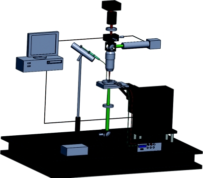
The primary components of our laser-guided cell micropatterning system were the laser source, the optics used to configure the beam for guidance, the cell-deposition chamber, the computer-controlled, motorized three-axis translational stage to move the chamber relative to the laser beam, the cell-feed mechanism to insert cells into the chamber, the imaging optics with a CCD camera, and the computer to control the cell-micropatterning procedure. The entire laser-guided cell micropatterning system, shown in Fig. 1, was built around a stationary downward-propagating laser beam that was focused with a small numerical aperture (NA ≈ 0.1) to produce a guidance region in the cell-deposition chamber, where a cell was trapped in the beam center and pushed downward to the substrate.
Figure 1.
(Color online) Schematics of the laser-guided cell micropatterning system.
Typical cell-micropatterning procedure began with preparation of the patterning substrate and the cell suspension. The cell suspension was loaded into a 50 μl microsyringe coupled with a hollow fiber. The substrate and the hollow fiber were placed and sealed into the cell-deposition chamber. The chamber was mounted on the three-axis motorized translational stage to move using an Xbox360 controller relative to the laser beam and imaging systems. The imaging system’s field-of-view and focus were adjusted to the guidance region of the laser beam and kept in that region during the entire cell pattern procedure. This allowed the user to freely navigate through the chamber by adjusting the chamber’s position via scanning the 3D translational stage that held the chamber. Cells were injected through the hollow fiber into the media-filled chamber. The horizontal plane projection the vertical laser beam viewed with the CCD camera was a point and was marked on the computer screen as a cross. When this point that indicated the position of the laser beam’s axis was centered onto a floating cell through moving the 3D translational stage, the laser guidance was started by opening the laser shutter to trap the cell. Once a cell was trapped, it was guided onto a desired point on the substrate again through moving the 3D translational stage. The process was repeated until the intended cell pattern was formed.
Optics configuration
The laser source used was a single-transverse-mode diode laser (200 mW, 830 nm, continuous wave (CW), S6020–200, Intense Inc.) attached to a diode laser mount (TCLDM9, Thorlabs Inc.), which provided current and temperature control. An aspheric collimating lens (f = 4.51 mm, NA = 0.55, C230TME-B, Thorlabs Inc.) was used immediately outside the diode laser chip followed by an anamorphic prism pairs (NT47–274, Edmund Optics) used to transform the elliptical beam into the circular one. Then the beam was expanded and steered by using a biconvex lens pair (f = 15 mm, D = 0.5 in. and f = 20 mm, D = 0.5 in., LB1092-B, LB1450-B, Thorlabs, Inc.). The second lens was mounted on a motorized translational stage (PT1-Z8, Thorlabs, Inc.) to steer the beam’s focus point so that the guidance region of the beam coincided with the object plane of the imaging system. The beam then passed through a 45° dichroic mirror (DMLP567, Thorlabs Inc.) that reflected the visible image to the CCD camera while allowing passage of the 830 nm beam. Next, the beam was focused into the cell-deposition chamber using a long-working-distance objective (20×, Mitutoyo Plan Apo Infinity-corrected, NT46-145, Edmund Optics) with NA = 0.42 and f = 10 mm. The illumination source was a collimated green (530 nm) 200 mW LED (M530L2, Thorlabs Inc.). The illumination beam was reflected upward by the dichroic mirror and through the bottom of the chamber, passed through the 20× objective, and was reflected to the camera by the dichroic mirror. Before the image carried by the illumination beam was captured by the CCD camera (XC-ST50 Sony), it was passed through several IR filters to remove artifacts from the guidance beam. The CCD camera was mounted on a 3D translational stage to allow the center of the CCD to be aligned to the laser guidance region.
Beam waist requirement for guidance
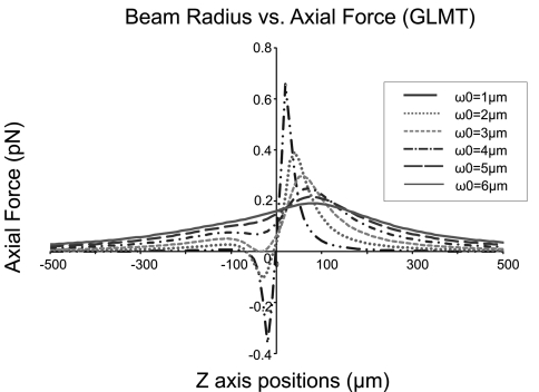
How the laser beam is focused is critical to achieve laser guidance. When the beam is not focused, there will be no radial trap and thus the cell cannot be guided. On the other hand, a strongly focused laser beam causes optical trapping.17 When this occurs, rather than being guided along the laser beam, the cells are trapped at the laser focus point. According to optical theory, the strength of a laser’s focus is determined by the laser beam waist. Thus, to generate a weakly focused laser beam and avoid optical trapping, guidance force was calculated theoretically using GLMT (Refs. 18 and 19) against different beam waists to estimate a proper beam-waist range for laser-guided cell patterning. The parameters for the theoretical calculations were selected based on our actual experiment’s conditions (wavelength: 830 nm; power: 175 mW; refractive index of the PBS medium: 1.33; average cell size: 10 μm; and average cell refractive index: 1.36).
Assuming that the beam waist was located at the zero point, the guidance forces were simulated with beam-waist width from 1 to 6 μm, as shown in Fig. 2. For a successful guidance, the guidance force should maintain the same vector direction to guide cell onto the substrate. One-direction guidance force was characterized by its positive values along the entire laser propagation pathway. When the beam-waist width is larger than 3 μm, the guidance force was positive along the beam axis to provide the laser guidance. However, when the width is equal to 1 and 2 μm, force values change from negative to positive near the focal point, and an optical trap is formed. Therefore, to achieve laser-guided-based cell patterning, the laser beam waist size must be greater than 3 μm.
Figure 2.
Simulation results for the beam waist requirement for laser guidance. The laser beam was considered to propagate from right side to left.
The beam-waist width in our actual system was designed to fulfill the above-mentioned requirement and experimentally estimated by the knife-edge scanning technique.20 The laser beam was systematically scanned using a razor’s edge mounted on a micromanipulator, which controlled the displacement of the knife-edge along the beam axis and across its section transversely. An optical power meter was placed in the path of the beam, downstream from the knife-edge scanning region, to measure the power of the unmasked transmitted beam. When designing our system, we first scanned the laser beam in ambient air and then scanned it in a chamber filled with cell-handling media. When the condition was switched from air to media, the beam waist expanded from 3.6 to 4.2 μm.21
Cell-deposition chamber
Living cells require media to survive. In the long term, the media provides nutrients and growth factors and facilitates transport of waste material. In the short term, the media provides a hydrating source with the proper osmolarity and pH required for homeostasis. During the cell patterning process, cells must be kept in such an environment. To provide this condition in our laser-guided cell micropatterning system, we designed a “patternscope” chamber, which used standard 35 mm Petri dishes or commercial multielectrode arrays (MEAs) as the substrate.
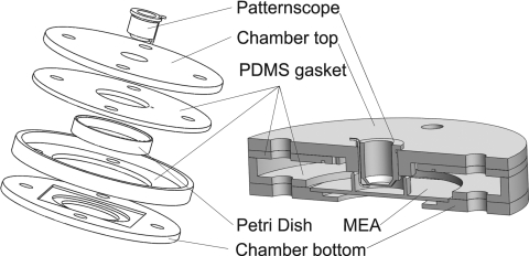
The patternscope design was characterized by a submersible laser passage window housed in a tubular structure that allowed rotation and height adjustment of the laser passage window and microinjection fiber. The patternscope component of the chamber included a fiber guide that allowed insertion and adjustable positioning of a microinjection fiber. In the patternscope-chamber design (Fig. 3), the substrate being patterned to must have a fluid containing wall (as in a Petri dish or the glass ring of a standard MEA). We clamped this wall tightly against a polydimethylsiloxane (PDMS) gasket attached to the underside of the top clamp. The PDMS gasket sealed the substrate dish and the patternscope, creating an airtight relatively dry seal. The dry seal would assist on preventing fungal contamination.
Figure 3.
Patternscope cell-deposition chamber design, exposure drawing with Petri dish (left) and assembly drawing with MEA with glass ring (right).
Nanoliter volumes of a cell suspension were injected into the chamber through a polyether ether ketone (PEEK) tubing to feed single cells into the guidance region of the laser beam. The imaging∕laser window was made from a fluorinated ethylene propylene (FEP) plug film that allowed vital gas exchange in the otherwise sealed chamber. Keeping the chamber sealed in this way helped reduce contamination and conserve the molarity of the media inside. The relative impermeability of FEP film to water vapor was especially important during time-lapse microscopy and electrophysiology experiments, when humidity is difficult to control. Use of FEP was based on the long-term culturing apparatus employed by Potter and DeMarse.22
The whole chamber was stabilized on a three-axis motorized stage (Aerotech FA90-25-25-25) driven by three Aerotech N-drive units communicating with the computer via IEEE1394. The stage was capable of submicron resolution and 25 mm travel distance in all three axes. An incubation system was built on the chamber to maintain optimal culture temperature during patterning to increase cell health and moderate convection forces, which can arise from the substrate’s absorbance of laser radiation. The system consisted of thin Kapton-coated heating elements and small resistance temperature detector (RTD), which were connected to proportional–integral–derivative (PID) controller (Omega CN9512). The PID controller was equipped with an autotune function, which would “learn” the temperature response characteristics of the system and calculate the appropriate current feedback to reach and maintain a specific temperature. During chamber assembly the RTD was placed in contact with the culture medium. The initial training of the PID controller was performed under typical experimental conditions with a fully assembled and loaded chamber. Five min prior to each experiment, the incubation system was turned on allowing the media to reach a steady temperature of 37 °C with ±1 °C variation.
System control software
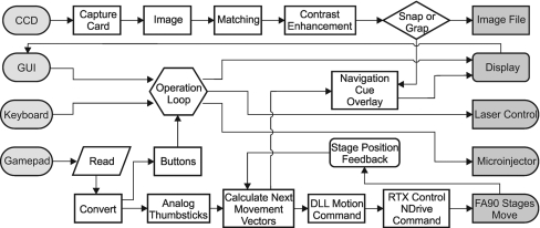
The control system was run on an Intel Core 2 Quad computer with 4 GB of RAM and windows XP. The control software was written in LABVIEW8.5, which allowed for the manual assignment of specific processes to individual processor cores. The Aerotech stage used real time executive (RTX) to communicate with the computer through an IEEE1394 port. RTX-enabled drivers were dedicated to one processor core and the firewire card to control of the Aerotech stage, leaving three processor cores, two of which were assigned exclusively, shown in Fig. 4. The LABVIEW program consists of four primary timed loops (1) to handle user inputs from the front panel, keyboard, and Xbox360 controller, (2) to capture, process, and display the patterning video with navigational overlays, (3) to read motion-control data from the analog sticks and compute the movement vectors, and (4) to issue motion commands to each of the three axes. Processes 3 and 4 were assigned their own processors and ran in parallel, allowing for the shortest loop periods (40 ms) and smoothest control. Motion commands were issued using .dlls, while low priority initialization and status commands were issued through subVIs supplied with the Aerotech A3200 software.
Figure 4.
Flow chart of system-control software.
The opening∕closing of the laser shutter and the laser intensity adjustment were controlled via serial port∕RS232 access through VISA in LABVIEW. The injection command and parameters of volume and rate were issued through a USB∕serial port adapter, which communicated with LABVIEW via RS232 access through VISA. Cell manipulation and navigation were primarily controlled by an Xbox360 controller because of Windows compatibility and long-term availability. The advantages of using this type of controller were its cost efficiency and ease of replacement. It had more inputs available than a typical joystick controller for the motorized stages. The analog thumbsticks were used to maneuver in X, Y, and Z. The mark∕recall buttons allowed the user to mark way points on the substrate, for example, an electrode. Pressing the microinjection button triggered an injection of cells into the chamber and commanded the motorized stage to bring those cells into the field-of-view and laser-guidance region. Then, the user maneuvered the cell into the center of the screen, where the laser was focused and pressed the laser button to open the laser shutter, turning on the laser guidance. Once the user captured the cell in the guidance beam, and it was held in the center of the field-of-view, an on-screen direction indicator pointed toward the previously marked way point. Following the indicator, the user navigated to the way point using the thumb sticks, carrying the cell along in the laser guidance region.
Cells
Cardiomyocytes
Adult cardiomyocytes were harvested from 100 g adult rats anesthetized by intraperitoneal injection of 45 mg∕kg 2% sodium pentobarbital (containing 1:200 Heparin). The whole heart was perfused for 5 min with Ca2+ free buffer [NaCl (113 mM), KCl (4.7 mM), KH2PO4 (0.6 mM), Na2HPO4 (0.6 mM), MgSO4 (1.2 mM), Phenol red (0.032 mM), NaHCO3(12 mM), KHCO3 (10 mM), 4-(2-hydroxyethyl)-1-piperazineethanesulfonic acid (HEPES) (10 mM), and Taurine (30 mM)]. Next, the heart was perfused with a digestive buffer [Liberase blendzyme 1 (0.25 mg∕ml), Trypsin (0.14 mg∕ml), 2,3-butanedione monoxime (BDM) (10 mM), CaCl2 (12.5 μM)] for 50 min. The heart was minced and digestion was stopped by stopping buffer [bovine calf serum (10%), CaCl2 (12.5 μM)]. Cells were then washed, purified, loaded into the microsyringe, and patterned to glassbottom dishes coated with 25 μg∕cm2 Laminin. The culture medium consisted of DMEM (13.37 g∕L), NaHCO3 (1.2 g∕L), 2,3-BDM (10 mM), bovine serum albumin (BSA) (0.1 mg∕ml), HEPES (15 mM), Penicillin Streptomycin (1%), and bovine calf serum (5%).
Neurons
Chick forebrain neurons were harvested from embryonic day 7 white leghorn chicks. In brief, the two forebrain lobes were removed and placed in 0.1% trypsin ethylenediaminetetraacetic acid (EDTA) for 5 min. The trypsin was then aspirated, and the digested tissue was washed in Media 199 supplemented with 10% fetal bovine serum (FBS). The wash∕stopping media was removed, and the tissue was resuspended in culture media. The cells were dissociated by triturating three times with a 21G syringe. The cells were incubated in a humidified atmosphere of 95% air and 5% CO2. Culture media consisted of astrocyte-conditioned Neurobasal Media with 2% B27, 100 ng∕ml NG4, 1X Glutamax, penicillin∕streptomycin, and getamicin. Daily, 50% of the culture media was changed.
RESULTS
Single-cell array pattern
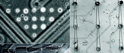
The primary purpose of the system described is to create patterns of cells. While these patterns may mimic the arrangements of native tissue, the single-cell control imposed on substrate is more useful for creating specific cell patterns designed to isolate cell–cell interaction phenomena for research purposes. Toward this end, we first demonstrated a simple array patterned with high resolution and tight registration to a feature on the substrate. Figure 5a shows chick forebrain neurons that were patterned to a preselected corner of a square on a gridded glass coverslip to form a right-triangle figure. To build the array, the first cell was guided onto the desired region on the coverslip. After the deposition, we executed a motion command and mark a second point with a lateral or vertical distance of 30 μm according to the precalibrated coordinate system, where the next cell was to be guided onto. This procedure was repeated several times to form the array. The average time for deposit one cell, including cell injection and single cell selection, was 45 s. The image was taken immediately after the array formation using the 20× objective that is part of the laser-guided system.
Figure 5.
Laser-guided cell micropatterns: (a) single-cell array; (b) adult cardiomyocyte alignment; and (c) neuronal network on MEA.
Single-neuron patterning on MEA
Patterning neurons on MEA has become a popular approach to studying how neuronal network structure influences the activity of neuronal populations. The most common configuration of such experiments involves the use of commercially available MEA (as from MultiChannel Systems, Germany or Ayanda) where a culture dish is formed by a glass ring placed on top of the planar chip. The glass ring has become such a standard component of MEAs that caps and perfusion systems fitted to the rings are now commercially available. The specially designed deposition chamber made it possible to pattern neurons onto the standard MEA with glass ring.
In combination with soft lithography microfabrication, our laser-guided cell micropatterning system was used to produce neuronal networks with defined connectivity and single-cell resolution. Soft lithography techniques were used to create a microstructure with multiple microwells and microtunnels over the MEA. An electrode on the MEA was in the bottom of each microwell.23 To study the electrical activity of a neuronal network, each single neuron was trapped and guided into a single microwell (that is, each microwell contained only one neuron), shown in Fig. 5c, which was also captured using the 20× objective immediately after the network was formed. A laser-patterned neuronal circuit with single-cell resolution was created and studied through cell culturing and electrophysiology. The electrical signal was acquired with the MEA every day after neuron patterning to study neuronal network formation (the results will be reported in the future).
Adult cardiomyocyte alignment
Adult cardiomyocytes are rod-shape cells of approximately 120 μm in length and 25–35 μm in diameter. Native cardiomyocytes are aligned so that neighboring cardiomyocytes are electrically and mechanically coupled through contact junctions. When adult cardiomyocytes are conventionally cultured in a dish, the resultant lack of myocyte end-to-end alignment is one reason for the dedifferentiation manifested by the irregular alignment of the sarcomeres.24 Studying mechanical functions of cardiomyocytes in vitro requires construction of a cell-culture model that replicates the most relevant characteristics of heart tissue.25, 26, 27 Using our laser-guided cell micropatterning system, we formed an end-to-end aligned pattern as follows: a cardiomyocyte was trapped, and the action of optical force in the focus region caused the cell to rotate into a vertical orientation while it was simultaneously guided to a particular section of the substrate. As soon as the lower end of the cell made contact with the substrate immediately next to the previously patterned cell, the laser was used to pull the cell in the direction of this previously patterned cell, thus trapping the cell and pushing it onto the substrate in end-to-end alignment with the previously patterned cell. The image in Fig. 5b was taken during the laser guidance procedure, showing that the fourth adult cardiomyocyte was guided and aligned to the end of the third aligned cell. The average time of aligning a single adult myocyte was about 90 s.
CONCLUSIONS
A cell micropatterning system based on laser-guidance technique was developed to pattern cells with a resolution that exceeds the error caused by inherent cell variation and irregularity. The cell micropatterning system was designed to be compatible with a variety of substrates that are standard in cell research. The ability to pattern through three dimensions makes this system compatible with substrate modification techniques used to control cell migration and neurite extension. The cell micropatterning system combined with microfabrication methods was used to create defined neuronal patterns with single-cell resolution. The system was also used to orient individual rod-shape cardiomyocytes in an aligned manner. This type of manipulation could be used to study the electrical and mechanical cell–cell interactions specific to morphological interfaces. After laser cell deposition, the cells may migrate in terms of cell–cell and cell–extracellular matrix (ECM) interactions. For example, our laser patterned neuronal array was maintained in 4 h before neuron migration was observed to distort the pattern. Consequently, surface patterning techniques may be required to confine the patterned cells for specific cell–cell interaction research. The bone marrow stem cells and rat neonatal cardiomyocytes have been deposited into a microdevice to study their electrical coupling using patch clamp technique at single cell resolutions. These results demonstrate that the laser-guided cell micropatterning system has the following special features:
Smooth control over cell position and orientation: the optimization of program code and use of parallel processing in the control system reduced the motion-control loop periods to less than 40 ms with a refresh rate of 25 Hz.
Substrate-registered patterning with high spatial resolution.
Compatibility with standard cell-culture devices: the chamber design successfully allowed use of 35 mm Petri dishes, MEAs with a 35 mm culture ring, and microfluidic chips.
3D cell manipulation: cell patterning is not dependent on the surface treatment required in conventional cell micropatterning. System can be used to place cells into 3D microdevices.
Unrestricted cell migration after patterning: unlike in conventional micropatterning techniques, which constrained cells within the protein patterned area, natural cell migration after initial laser patterning is allowed. Therefore, cell–cell and cell–ECM interactions can be studied without specific cell or ECM confinement. For example, we have observed neuron guidance by glial cells after the glial cells are spread following laser neuron-glia deposition.
These advantages of the laser-guidance based cell micropatterning system make it a tool capable to achieve site- and time-specific placements of an individual cell in a cell culture or a microdevice for systematic investigation of cell–cell, cell–ECM, and cell–electrode interactions.
ACKNOWLEDGMENTS
This work has been partially supported by NIH SC INBRE (2p20rr16461-05 and its supplementary Grant No. 3P20RR016461-09S2), SC COBRE (P20RR021949), and Career Award (1k25hl088262-01); DoD Era of Hope Award (BC044778); NSF MRI (CBET-0923311); and the Program for Key International ST Cooperation Projects of the Ministry of Science of China (2008DFA30590), X.Y. acknowledges National Natural Science Foundation of China (NSFC) for Grant No. 60778045.
Reference
- Kondo R. P., Dederko D. A., Teutsch C., Chrast J., Catalucci D., Chien K. R., and Giles W. R., J. Physiol. 571, 131 (2006). 10.1113/jphysiol.2005.101428 [DOI] [PMC free article] [PubMed] [Google Scholar]
- Borisov A. B., Martynova M. G., and Russell M. W., Histochem. Cell Biol. 129, 463 (2008). 10.1007/s00418-008-0378-y [DOI] [PMC free article] [PubMed] [Google Scholar]
- Chung C. Y., Bien H., and Entcheva E., J. Cardiovasc. Electrophysiol. 18, 1323 (2007). 10.1111/j.1540-8167.2007.00959.x [DOI] [PubMed] [Google Scholar]
- Hubbard M. L., Ying W., and Henriquez C. S., Europace 9, vi20 (2007). 10.1093/europace/eum203 [DOI] [PubMed] [Google Scholar]
- Kieken F., Mutsaers N., Dolmatova E., Virgil K., Wit A. L., Kellezi A., Hirst-Jensen B. J., Duffy H. S., and Sorgen P. L., Circ. Res. 104, 1103 (2009). 10.1161/CIRCRESAHA.108.190454 [DOI] [PMC free article] [PubMed] [Google Scholar]
- Felleman D. J. and Essen D. C. Van, Cereb. Cortex 1, 1 (1991). 10.1093/cercor/1.1.1-a [DOI] [PubMed] [Google Scholar]
- Hsu J. Y., Stein S. A., and Xu X. M., J. Neurosci. Res. 80, 330 (2005). 10.1002/jnr.20472 [DOI] [PubMed] [Google Scholar]
- Poluch S. and Juliano S. L., Glia 55, 822 (2007). 10.1002/glia.20488 [DOI] [PubMed] [Google Scholar]
- Li X., Hou S., Feng X., Yu Y., Ma J., and Li L., Colloids Surf. B 74, 370 (2009). 10.1016/j.colsurfb.2009.07.039 [DOI] [PubMed] [Google Scholar]
- Jang K., Sato K., Mawatari K., Konno T., Ishihara K., and Kitamori T., Biomaterials 30, 1413 (2009). 10.1016/j.biomaterials.2008.11.013 [DOI] [PubMed] [Google Scholar]
- Nahmias Y. and Odde D. J., Nat. Protoc. 1, 2288 (2006). 10.1038/nprot.2006.386 [DOI] [PubMed] [Google Scholar]
- Barron J. A., Wu P., Ladouceur H. D., and Ringeisen B. R., Biomed. Microdevices 6, 139 (2004). 10.1023/B:BMMD.0000031751.67267.9f [DOI] [PubMed] [Google Scholar]
- Boland T., Xu T., Damon B., and Cui X., Biotechnol. J. 1, 910 (2006). 10.1002/biot.200600081 [DOI] [PubMed] [Google Scholar]
- Philipsborn A. C. von, Lang S., Bernard A., Loeschinger J., David C., Lehnert D., Bastmeyer M., and Bonhoeffer F., Nat. Protoc. 1, 1322 (2006). 10.1038/nprot.2006.251 [DOI] [PubMed] [Google Scholar]
- Hwang H., Kang G., Yeon J. H., Nam Y., and Park J. K., Lab Chip 9, 167 (2009). 10.1039/b810341k [DOI] [PubMed] [Google Scholar]
- Hajizadeh F. and Reihani S. N., Opt. Express 18, 551 (2010). 10.1364/OE.18.000551 [DOI] [PubMed] [Google Scholar]
- Samadi A. and Reihani N. S., Opt. Lett. 35, 1494 (2010). 10.1364/OL.35.001494 [DOI] [PubMed] [Google Scholar]
- Lock J. A., Appl. Opt. 43, 2532 (2004). 10.1364/AO.43.002532 [DOI] [PubMed] [Google Scholar]
- Lock J. A., Appl. Opt. 43, 2545 (2004). 10.1364/AO.43.002545 [DOI] [PubMed] [Google Scholar]
- Suzaki Y. and Tachibana A., Appl. Opt. 14, 2809 (1975). [DOI] [PubMed] [Google Scholar]
- Ma Z., Julie X., Yun J., Wei Y. Z., Burg K. J., Yuan X. C., and Gao B. Z., Proc. SPIE 7400, 1 (2009). [Google Scholar]
- Potter S. M. and DeMarse T. B., J. Neurosci. Methods 110, 17 (2001). 10.1016/S0165-0270(01)00412-5 [DOI] [PubMed] [Google Scholar]
- Pirlo R. K., Peng X., Yuan X. C., and Gao B. Z., OptoElectron. Lett. 4, 0387 (2008). 10.1007/s11801-008-8059-6 [DOI] [PMC free article] [PubMed] [Google Scholar]
- Camelliti P., Gallagher J. O., Kohl P., and McCulloch A. D., Nat. Protoc. 1, 1379 (2006). 10.1038/nprot.2006.203 [DOI] [PubMed] [Google Scholar]
- Bartholoma P., Gorjup E., Monz D., Reininger-Mack A., Thielecke H., and Robitzki A., J. Biomol. Screen 10, 814 (2005). 10.1177/1087057105280070 [DOI] [PubMed] [Google Scholar]
- Kaneko T., Kojima K., and Yasuda K., Biochem. Biophys. Res. Commun. 356, 494 (2007). 10.1016/j.bbrc.2007.03.005 [DOI] [PubMed] [Google Scholar]
- Camelliti P., McCulloch A. D., and Kohl P., Microsc. Microanal. 11, 249 (2005). 10.1017/S1431927605050506 [DOI] [PubMed] [Google Scholar]


