Abstract
In this paper, we propose a method for automatic determination of position and orientation of spine in digitized spine X-rays using mathematical morphology. As the X-ray images are usually highly smeared, vertebrae segmentation is a complex process. The image is first coarsely segmented to obtain the location and orientation information of the spine. The state-of-the-art technique is based on the deformation model of a template, and as the vertebrae shape usually shows variation from case to case, accurate representation using a template is a difficult process. The proposed method makes use of the vertebrae morphometry and gray-scale profile of the spine. The top-hat transformation-based method is proposed to enhance the ridge points in the posterior boundary of the spine. For cases containing external objects such as ornaments, H-Maxima transform is used for segmentation and removal of these objects. The Radon transform is then used to estimate the location and orientation of the line joining the ridge point clusters appearing on the boundary of the vertebra body. The method was validated for 100 cervical spine X-ray images, and in all cases, the error in orientation was within the accepted tolerable limit of 15°. The average error was found to be 4.6°. A point on the posterior boundary was located with an accuracy of ±5.2 mm. The accurate information about location and orientation of thespine is necessary for fine-grained segmentation of the vertebrae using techniques such as active shape modeling. Accurate vertebrae segmentation is needed in successful feature extraction for applications such as content-based image retrieval of biomedical images.
Key words: Vertebrae segmentation, spine X-ray, content-based image retrieval, mathematical morphology
Introduction
The MPEG-7 provides a set of standardized descriptors that facilitates rapid search by content of various types of multimedia information such as graphics, images, video, film, music, speech, sound, text, etc.1 As shape is an important property for similarity evaluation in the case of images, region-based and contour-based descriptors are proposed by MPEG-7.2 As the biomedical images of the same class are highly similar, low-level image features of the object of interest, e.g., shape of vertebra body in case of spine images, have to be identified for efficient indexing. With the increased popularity of picture archival and communication system (PACS), the number of stored digital medical images is numerous. Manual indexing using text describing the pathology is error prone and a prohibitively expensive task for large medical databases. Thus automatic methods are necessary for feature representation of the pathology of interest, and they have to address the conflicting goals of reducing feature dimensionality while retaining important and often subtle biomedical features. Efficient content-based image indexing and retrieval will allow physicians to identify similar past cases. By studying the diagnoses and treatments of past cases, physicians may be able to better understand new cases and make better treatment decisions.
Modern communication standards use nonimage data for standardized description of information such as technical parameters related to the imaging modality, patient information, body region examined, study, etc. To provide comprehensive, detailed coverage for multispecialty biomedical imaging, the College of American Pathologists (CAP), secretariat of the Systematized Nomenclature of Human and Veterinary Medicine (SNOMED), have entered into partnership with the Digital Imaging and Communications in Medicine (DICOM) Standards Committee and other professional organizations to develop a nomenclature for diagnostic imaging applications.3 The SNOMED DICOM microglossary was developed to provide context-dependent value sets for DICOM coded-entry data elements and semantic content specifications for reports and other structures composed of multiple data elements.4 Although the capability of storing explicitly labeled coded descriptors in DICOM images and reports improves the potential for selective retrieval of images and related information, the controlled terminology within the DICOM tables has been found to be insufficiently detailed for order entry systems.5,6 Thus manual textual index entries are mandatory to retrieve medical images from digital archives even in DICOM format, which are inefficient. The currently proposed MPEG-7 shape descriptors such as Zernike Moment Descriptor and Curvature Scale Space2 are not very useful in the context of medical image indexing. For standardization purposes as in MPEG-7, appropriate low-level features of each selected class of biomedical images need to be defined instead of feature extraction methods. The usage of MPEG-7 in medical context is still in its infancy, and the ongoing rigorous research worldwide is expected to result in effective content-based medical image retrieval in the near future.
The indexing of the spine X-ray images is addressed using a hierarchical procedure. The distinctive region of the image, including the general spine region, is first being segmented at a gross level of detail. This is followed by a fine-grained segmentation of the spine region into individual vertebra. Much research in this direction has been carried out by The Lister Hill National Center for Biomedical Communications, a research and development division of the National Library of Medicine (NLM). In the literature, some human-assisted methods for the segmentation of the vertebrae using active contour segmentation (ACS) and active shape modeling (ASM)7 techniques have been reported.8–11 The fully automated methods proposed in the literature can be broadly classified into two groups: (1) based on landmark points such as skull, shoulder, etc. to determine the characteristic curves assumed to lie in the spine region12–14 and (2) a template-matching-based method.15,16
The first category includes a method proposed by Zamora et al.13 based on line integrals of image gray scale to determine approximate spine axis location. They reported an orientation error in their algorithm of less than 15° for 34 of the cases in a test set of 40 cervical spine images. The dynamic-programming-based method proposed for spine axis localization14 in the region of interest computed from basic landmark points claims success for 46 cases in a test set of 48 images. In the template-matching method, a customized implementation of the generalized Hough transform (GHT) is used for the object localization.15 The GHT was applied to the test set of 50 images using the mean template obtained from the landmark points (LMP) marked by expert radiologists. The results reported claim an average 72.06 points out of 80 LMP inside the bounding box and an average orientation error of 4.16°. The state-of-the-art solution to the problem of vertebrae segmentation in digitized spine X-ray images is a hierarchical approach that combines three different methodologies.17,18 The first module is a customized generalized Hough transform (GHT) algorithm that is used to find an estimate of vertebral pose within target images. The second module is a customized version of active shape models (ASM) that is used to combine gray-level values and edge information to find vertebral boundaries. Active shape modeling is a technique that captures the variability of shape and local gray-level values from the training set of images to build two models, one for shape and for gray-level values. Segmentation with ASM is achieved by iteratively deforming the shape model toward the boundaries of the objects of interest as guided by gray-level model. The ASM module needs to be correctly initialized with the location and orientation of the spine for accurate segmentation. The third module is a customized deformable model (DM) approach based on the minimization of external and internal energies which allows the capture of fine details such as vertebral corners.18
The success of the GHT-based technique depends on three parameters: (1) gradient information, (2) representativeness of the template, and (3) reckoning of the votes in the accumulator structure. A clear edge image is required for obtaining gradient information accurately, and a template must adequately represent the target object to obtain the necessary votes in the accumulator. It is common to find great variability in shape of the cervical vertebrae across a large set of images. This is a drawback of the GHT-based technique. The shape variability captured by mean template is limited, and addition of more templates to capture more variability increases the computational complexity.
In this paper, we propose an alternative method for spine localization using mathematical morphology making use of the vertebral morphometry. The method computes the orientation of the spine and a point on the right edge of the vertebral faces. As this method is not based on predefined templates, it works well over a wide range of images. The method was successfully tested for cervical spine images. It can be used as the initialization step of the automatic vertebrae segmentation using ASM.
Materials and Methods
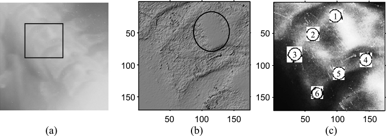
The vertebrae gray-scale characteristics are complex. The spine exhibits visually recognizable ridge characteristics, usually extending the length of the spine, but particularly visible in the region of the lower vertebrae. Figure 1(a) shows the original gray-scale profile of a cervical spinal column. The gray-scale profile of the vertebra, marked in Figure 1(a) using a rectangle, is demonstrated using the surface characteristic plot in Figure 1(b). The gray-scale image is modeled as a topographic model of a terrain where the pixel value represents the height at the pixel coordinates. The surface is rendered using the top-view direction, and the light direction is in the northwest direction. The ridge point cluster on the posterior boundary of the vertebra is encircled in Figure 1(b). The boundary of a vertebra is usually marked using six standard morphometric points as shown in Figure 1(c). These six points have the semantic relevance as follows:
Points 1 and 4 mark the upper and lower posterior corners of the vertebra, respectively.
Points 3 and 6 mark the upper and lower anterior corners of the vertebra, respectively.
Points 2 and 5 mark the median along the upper and lower vertebra edge in the sagittal view, respectively.
Fig 1.
(a) Original gray-scale image of a cervical spinal column. (b) Surface characteristic plot of the vertebra. (c) Six standard morphometric points marked on the vertebra body in a histogram equalized image.
The aim of fine-grained vertebrae segmentation is to determine these boundary points and any additional landmark points necessary for indexing the image automatically. The curvature of a curve that is fit into the midpoints of the top and bottom (points 2 and 5) of each vertebral body for all the vertebrae of the same type (e.g., cervical) can be taken as the curvature of the spine in that region.13 These midpoints do not have any prominent associated visual characteristics, either in gray-scale or in shape. So they are very poor candidates for detection until the spine anatomy is already known after a finer-grained segmentation. However, the gray-scale ridge points appear to lie on the vertebral faces or near the right edges of the vertebral faces. Hence a line joining these might be conjectured to give a reasonable approximation to the spine location and orientation. These ridge points have bright gray-scale values and can be visualized as being on the local higher regions in elevation space of the spine area. Considering these facts, a method based on mathematical morphology was introduced to detect these points as local maxima.
Proposed Method
The detection of ridge point clusters in the outer boundary of the vertebrae is carried out using mathematical morphological operation. Binary mathematical morphology is an algebraic system based on set theory that provides two basic operations: dilation and erosion.19 The dilation operation enhances the bright areas in the image and the darker details are reduced. Erosion enhances the dark areas in the image and can remove bands of noise, if high values are not present in large neighborhoods.
A gray-scale image is defined as a 3-D set, and two images f and b can be represented as follows.
 |
1 |
where g(x, y) and h(x, y) are the gray scale of the pixel at location (x, y).
In mathematical morphology, the image b that is used for processing image f is called a structuring element (SE). For a flat SE (a binary), the erosion is simplified to find the minimum gray level and the dilation to find the maximum during the process in the neighborhood defined by the SE.
The dilation of f by b can be represented as
 |
2 |
and erosion of f by b as
 |
3 |
where (x ± x1), (y ± y1) ε Df and x1, y1 ε Db; Df and Db are the domains of f and b, respectively.
A two-dimensional flat SE, b, which is “disk”-shaped in the Euclidean metric and centered at the origin, is constructed as follows.
 |
4 |
where r is the radius of the disk, chosen as 20.
For each of the test image, a boundary area was used on all four image sides (left, right, top, and bottom), and pixels that were within this boundary limit were not processed. This was performed to avoid the frequent problems encountered by the presence of very bright pixels as a result of light leakage near the edges of the images. As a preprocessing step, histogram equalization is performed on the image for enhancing the contrast between the vertebrae and the surrounding regions. The contrast-enhanced image is morphologically opened with the SE. The opening operation includes two procedures: erosion followed by dilation.
 |
5 |
The top-hat transformation19 is then performed by subtracting the opened image from the original image to detect objects having the size of the SE and high gray-scale profile.
 |
6 |
All the eight-connected structures that are lighter than their surroundings and connected to the image border are then removed by an erosion operation. This operation removes some of the nonspine edges in the image. Any grain (i.e., connected component) with area less than 100 in the neighborhood defined by a “cross”-shaped flat SE (Eq 7) is removed to eliminate isolated clutters in the image.
 |
7 |
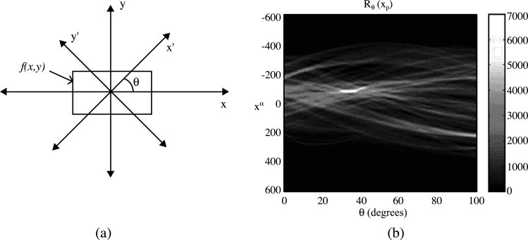
The resultant image is a coarsely segmented one with ridges on the vertebral faces enhanced. The ridge point clusters located in each vertebra face need to be connected together to mark the outer boundary of the spine. The Radon transform20 of the segmented image is computed for locating the strongest line in the image. The projection of the image matrix onto x-axis in the range of 0–100° is found. A projection of a two-dimensional function at a particular angle is the line integral inthat direction. The Radon transform of the image function f(x,y) parallel to the y′-axis can be computed as follows:
 |
8 |
where
 |
The geometry of the Radon transform is shown in Figure 2(a), and the Radon coefficient values computed for various angles in a test image are shown in Figure 2(b). The locations of strong peaks in the Radon transform matrix correspond to the high line integral values in the image. As the segmented image has the ridge point clusters boosted, a line joining these points will correspond to the strongest peak in the Radon transform matrix. From the orientation (θ) and coordinate location on the x′-axis (xp) of the largest absolute value of radon coefficient, a corresponding y′-coordinate (yp) can be determined. Now we know a point (xp, yp) in the posterior boundary and the orientation of the spine. A line drawn passing through (xp, yp) and perpendicular to θ marks the posterior boundary of the spine in the original X-ray image. The coarse level segmentation convergence is said to be achieved if the error in computed orientation and location of the posterior boundary with respect to the ground truth information is within tolerable limits.
Fig 2.
(a) The geometry of the Radon transform. (b) The Radon transform of a test image using 100 projections.
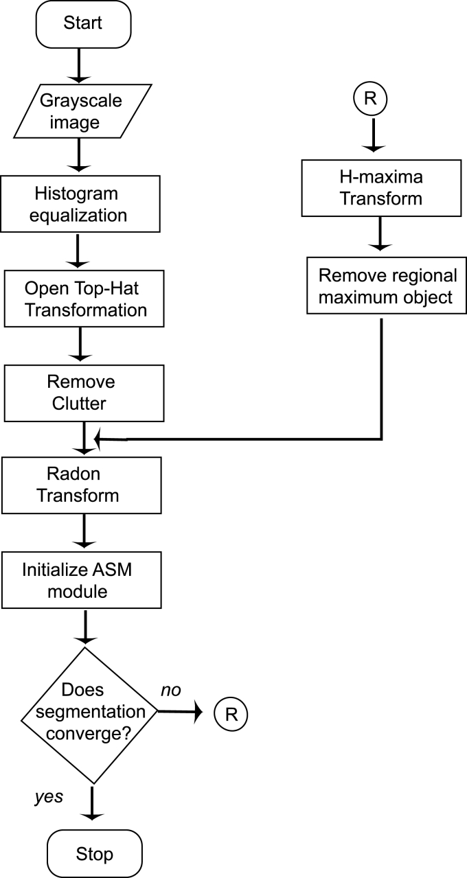
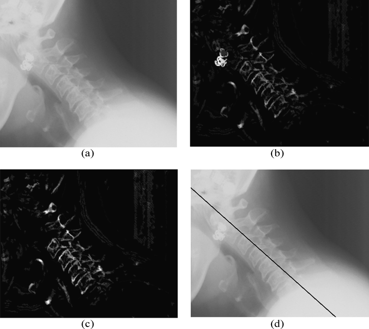
In some cases, where the image contains metallic objects such as ornaments, orthodontic treatment accessories, etc., failure of segmentation convergence occurs. This is because of the higher gray-scale value of these objects than the spine ridge points. In such cases, the proposed method will fail as the Radon transform locates the metallic objects instead of spine ridges because of its high gray-scale value. This can be corrected by another pass, in which the metallic object is detected and removed from the top-hat segmented image. The removal of the external objects can be carried out by using H-Maxima transformation,21 which suppresses all maxima in a given image whose height is lower than a given a threshold value. The regional maxima are connected components of pixels with an intensity value above a specified threshold and whose external pixels have a lower intensity. The threshold is fixed as the 90% of the maximum gray-scale value of the coarsely segmented image. As the metallic object has higher gray-scale value, it will be identified as the regional maxima and is subtracted from the coarsely segmented image before Radon transform computation. The H-Maxima transform is computed in a two-dimensional eight-connected neighborhood. This coarsely segmented image with foreign object removed and ridge points boosted is subjected to Radon transform computation as already explained. A flow chart representation of the complete process is given in Figure 3.
Fig 3.
The flowchart of the vertebrae segmentation process.
Results and Discussion
We have tested the algorithm on an ensemble of 100 images chosen from the archive maintained by National Library of Medicine (NLM) as part of the second National Health and Nutrition Examination Survey (NHANES II).22 The digitized X-ray images were originally generated from cervical radiographs using a Lumisys laser scanner at a resolution of 146 dpi. The candidate images were randomly chosen from the database having various image size and spine orientations. The lateral view cervical spine images had pixel depth of 8 bits. The seven vertebrae present in a cervical image are usually referred to as C1–C7.
For each of the images in our test set, we used the expert-collected (x, y) coordinate (provided by NLM) of the posterior bottom point [point 4 in Figure 1(b)] for C2 and C6 (or C5) vertebrae. The slope of the straight line fit to the spine using these points is taken as the ground truth of spine orientation for each image in the test set. The orientation of the line joining point 4 or point 5 (middle point of bottom face of vertebra body) of each vertebrae will be the same as they are parallel. We chose to connect point 4 of each vertebra, which is on the posterior boundary, so that the computed location accuracy also can be evaluated. The error in orientation was computed by taking the absolute difference of the spine orientation computed using the proposed algorithm and that obtained as the ground truth for each of the image in the test set. From the literature, it is observed that a tolerance up to 15° is permissible in orientation estimation.14 The absolute error was found to be within the tolerable limit of 15° for all the 100 images in the test set. For eight cases, the algorithm had to undergo a second pass after removal of the metallic objects present in them. Table 1 tabulates the percentage of the number of images that fall in different ranges of the orientation error. It is seen from the table that for more than 80% of the cases, the error is less than 6°. The average orientation error for 100 cases was found to be 4.6°.
Table 1.
Computed spine orientation accuracy
| Serial Number | Orientation Error Range (Degrees) | Percentage of Images in the Range |
|---|---|---|
| 1 | 0–3 | 57 |
| 2 | 3–6 | 25 |
| 3 | 6–9 | 12 |
| 4 | 9–12 | 3 |
| 5 | 12–15 | 3 |
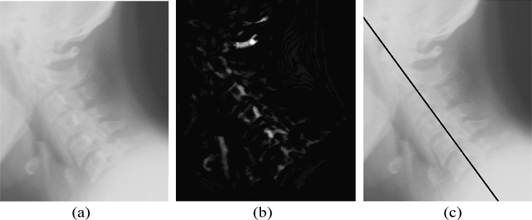
The accuracy of the location of the point computed can be calculated by computing the perpendicular distance from the point to the straight line approximated from the ground truth data using analytical geometry. The maximum distance was found to be in ±30-pixel range, which is approximately 5.2 mm as the images are having a resolution of 146 dpi. A straight line is approximated using the location and slope of the point computed to draw a marker on the posterior boundary of the spine using basic analytical geometry. Figure 4 demonstrates the images at various stages of the algorithm, and a marker is drawn on the computed spine location. Figure 5 shows the case of an image with a foreign object present.
Fig 4.
(a) Cervical spine image. (b) Segmented image using mathematical morphology. (c) A marker drawn using computed spine location and orientation.
Fig 5.
(a) Cervical spine image containing a metallic object. (b) Segmented image using mathematical morphology. (c) Image after removal of the metallic object using H-Maxima transform. (d) A marker drawn using computed spine location and orientation.
The location of the posterior boundary of the spine and its orientation information can be used to define a bounding box containing the spine to reduce the processing load in the finer level segmentation. The image could be rotated for the orientation of the spine, so that spine will align parallel to the vertical axis. The width of the bounding box should be chosen, based on the resolution of the image, in such a way to include the entire vertebra body in the box. For the 146-dpi images, a width of 250 pixels (from posterior to anterior boundary) was found to contain the vertebra body, even in cases of spines with large curvature. The length of the bounding box can be taken as the length of the image itself.
Conclusion
A novel method using mathematical morphological operators for accurate determination of vertebrae location and orientation in spine X-ray images is discussed in this paper. This algorithm is based on the spine morphometry and hence works well even in smeared images, without any human intervention. The maximum error in the computed location of the spine posterior boundary was found to be ±5.2 mm and spine orientation ±15°. The average error in orientation was found to be 4.6° for a test set of 100 spine images. This technique is a robust one for use in the initial phase of the fine-grained vertebrae segmentation. The boundary points in the vertebra body are useful features for spine image indexing for various pathologies such as osteoarthritis, disk space narrowing, etc. We are also investigating the applications of these boundary descriptors of the vertebrae in various spine regions for image indexing.
Acknowledgments
This research was partly funded by Council for Scientific and Industrial Research, India. We are also thankful to Mr. L.R. Long, National Library of Medicine, for providing the NHANES database.
References
- 1.Martinez JM, Koenen R, Pereira F. MPEG-7: the generic multimedia content description standard part 1. IEEE Multimed. 2002;9:78–87. doi: 10.1109/93.998074. [DOI] [Google Scholar]
- 2.Miroslaw B. MPEG-7 visual shape descriptors. IEEE Trans Circuits Syst Video Technol. 2001;11:716–719. doi: 10.1109/76.927426. [DOI] [Google Scholar]
- 3.Bidgood WD, Korman LY, Golichowski AM, Hildebrand PL, Mori AR, Bray BB, Brown NJG, Spackman KA, Dove SB, Schoeffler K. Controlled terminology for clinically-relevant indexing and selective retrieval of biomedical images. Int J Digit Libr. 1997;3(1):278–287. doi: 10.1007/s007990050022. [DOI] [Google Scholar]
- 4.Bidgood WD. The SNOMED DICOM microglossary-controlled terminology resource for data interchange in biomedical imaging. Methods Inf Med. 1998;37(4–5):404–414. [PubMed] [Google Scholar]
- 5.Kimura M, Kuranishi M, Sukenobu Y, Watanabe H, Nakajima T, Morimura S, Kabata S. JJ1017 image examination order codes—standardized codes supplementary to DICOM for image modality, region, and direction. Proc SPIE. 2002;4685:307–315. doi: 10.1117/12.467021. [DOI] [PMC free article] [PubMed] [Google Scholar]
- 6.Güld MO, Kohnen M, Keysers D, Schubert H, Wein BB, Bredno J, Lehmann TM. Quality of DICOM header information for image categorization. Proc SPIE. 2002;4685:280–287. doi: 10.1117/12.467017. [DOI] [Google Scholar]
- 7.Cootes TF, Taylor CJ. Statistical models of appearance for medical image analysis and computer vision. Proc SPIE (Med Imaging) 2001;4322:236–248. doi: 10.1117/12.431093. [DOI] [Google Scholar]
- 8.Xu X, Lee DJ, Antani S, Long LR: Localizing contour points for indexing an X-ray image retrieval system. Proc. 16th IEEE Symposium on Computer-Based Medical Systems, IEEE Computer Society, 2003, pp 169–174
- 9.Smyth PP, Taylor CJ, Adams JE. Vertebral shape: automatic measurements with active shape models. Radiology. 1999;211:571–578. doi: 10.1148/radiology.211.2.r99ma40571. [DOI] [PubMed] [Google Scholar]
- 10.Long LR, Thoma GR: Use of shape models to search digitized spine X-rays. Proc. of IEEE Computer Based Medical Systems 2000, 2000, pp 255–260
- 11.Long LR, Thoma GR: Computer assisted retrieval of biomedical image features from spine X-rays: progress and prospects. Proc. 14th Symposium on Computer-Based Medical Systems, 2001, pp 46–50
- 12.Long LR, Thoma GR: Feature indexing in a database of digitized X-rays. Proc. of SPIE Medical Imaging, 4315:393–403, 2001
- 13.Zamora G, Sari-Sarraf H, Mitra S, Long R. Estimation of orientation and position of cervical vertebrae for segmentation with active shape models. Proc. SPIE Med Imaging. 2000;4322:378–387. [Google Scholar]
- 14.Long LR, Thoma GR. Landmarking and feature localization in spine X-rays. J Electron Imaging. 2001;10:939–956. doi: 10.1117/1.1406503. [DOI] [Google Scholar]
- 15.Tezmol A, Sari-Sarraf H, Mitra S, Long R: Customized Hough transform for robust segmentation of the cervical vertebrae from X-ray images. Proc. 5th IEEE Southwest Symposium on Image Analysis and Interpretation, 2002, pp 224–228
- 16.Yalin Z, Nixon MS, Allen R: Automatic lumbar vertebrae segmentation in fluoroscopic images via optimized Concurrent Hough Transform. Proc. of the 23rd Annual International Conference of the IEEE Engineering in Medicine and Biology Society, 2001, pp 2653–2656
- 17.Thoma GR: Annual Report—Communications Engineering Branch. LHNCBC, NLM, 2002
- 18.Zamora G, Sari-Sarraf H, Long LR. Hierarchical segmentation of vertebrae from X-ray images. Proc. SPIE Med Imaging. 2003;5032:631–642. [Google Scholar]
- 19.Gonzalez R, Woods R. Digital Image Processing. 2. India: Pearson Education; 2002. pp. 519–561. [Google Scholar]
- 20.Bracewell R, Ronald N. Two-Dimensional Imaging. Englewood Cliffs, NJ: Prentice Hall; 1995. pp. 505–537. [Google Scholar]
- 21.Pierre S. Morphological Image Analysis: Principles and Applications. New York: Springer-Verlag; 1999. [Google Scholar]
- 22.http://archive.nlm.nih.gov/proj/ftp/ftp.php, National Library of Medicine, NHANES II X-ray images


