Abstract
Image quality assurance has traditionally been a high priority in medical imaging departments. Recently, it has often been neglected with the transition from hard copy (film) to soft copy (computer) display systems, which could potentially result in difficulty in reading images or even misdiagnosis. This transition therefore requires careful management such that comparable image quality is achieved at a minimum. It is particularly difficult to maintain appropriate image quality in the clinical settings outside of medical imaging departments because of the volume of display systems and the financial restraints that prohibit the widespread use of dedicated computers and high-quality monitors. In this study, a protocol to test and calibrate display systems was developed and validated by using an inexpensive calibration tool. Using this protocol, monitors were identified in a hospital in which image quality was found to be inadequate for medical image viewing. It was also found that most monitors could achieve a substantial increase in image quality after calibration. For example, the 0 and 5% luminance difference was discernable on 30% of the piloted display systems before calibration, but it was discernable on 100% post calibration. In addition, about 50% of the piloted display systems did not have the maximum luminance (white level) suitably set, and 35% of them did not have the minimum luminance (dark level) suitably set. The results indicate that medical display systems must be carefully selected and strictly monitored, maintained, and calibrated to ensure adequate image quality.
Key words: Image quality, display system, calibration, quality control, quality assurance, monitor, medical imaging, softcopy, cathode ray tube, liquid crystal display, DICOM 14, Grayscale Standard Display Function, SMPTE, luminance
Introduction
Although the quality of medical images (digital or otherwise) is strictly controlled during acquisition, it is often poorly maintained for soft-copy image review. Image quality control of softcopy display systems is often neglected because it can be an expensive and complex process to ensure. Most health institutions cannot afford to standardize on high-end medical display systems, but instead have a mix of various types1 [cathode ray tube (CRT) vs. liquid crystal display (LCD), color vs. monochrome], manufacturers, sizes, and age of monitors.
Over the past decades, photographic-quality control standards and recommendations for traditional film have been highly developed.2–5 The current guidelines include recommendations in areas such as viewbox brightness and homogeneity, processor cleaning, film quality testing, and film processing temperature. In contrast, as of yet there are no comprehensive standards or regulations for quality assurance of soft-copy display systems. The limited amount of published literature regarding image quality control of soft-copy display systems is often inconsistent and usually only focused on CRT and not on LCD monitors, which are becoming very popular for medical image review. A few institutions have created their own calibration protocols, with some developing their own metrics.6–8 The American Association of Physicists in Medicine Task Group 18 is in the process of developing more recommendations on image quality control.9
This article discusses and demonstrates the importance of maintaining image quality of soft-copy display systems, the development of a calibration protocol, and recommendations on how to achieve image quality control.
Materials and Methods
The following monitor image quality protocol was based on experience, published guidelines, and published image quality control methods by other healthcare institutions.5,7,10–12 A commercial calibration kit (VeriLUM by Image-Smiths Inc., Germantown, MD, USA) was used to measure the luminance via a photometer and to calibrate the monitors.
Calibration Protocol
Monitor Cleaning
Display systems should be cleaned regularly with monitor cleaner to remove fingerprints and other stains. There are many different types of commercial monitor cleaners, including sprays (to be sprayed on a soft cloth before application), individual wipes, and boxed wipes. Cleaning solutions can vary from being polymer-based to a solution of 50% water and 50% isopropyl. Care should be taken not to use alcohol-based or ammonia-based cleaners because it could permanently damage the screen surface (e.g., turning LCD screens yellow and brittle, or damaging CRT monitor antiglare coatings).
Dark Level
The minimum luminance (dark level) must first be properly set by changing the “brightness setting.” Ideally, monochrome CRT monitors can be set between 0.2 and 0.5 cd/m2. Monochrome LCD monitors can usually be set at about 1.0 cd/m2. The lower the dark level the better, but at the same time, the monitor must be able to provide a maximum luminance adequate for the particular application (e.g., 170 cd/m2 for most images displayed on color monitors, and 350 cd/m2 for most images displayed on monochrome monitors).
Maximum Luminance
The maximum luminance should be set by changing the “contrast setting.” The optimal value for this setting will depend on several factors. If there is a high level of ambient lighting in the room, then a higher maximum luminance will be required to give the same image quality that is required in a darker area. If the maximum luminance, however, is set too high for a particular monitor, it will significantly shorten its useful life span. The ambient lighting should therefore be minimized if at all possible. For new monochrome monitors, the optimal scenario to prolong their useful life span would be to drive the monitor at 50% of its capable maximum luminance to achieve 300–350 cd/m2. New color monitors should be driven at about 70% of their capable maximum luminance (about 250 cd/m2) to achieve about 170 cd/m2.
DICOM 14 Grayscale Standard Display Function
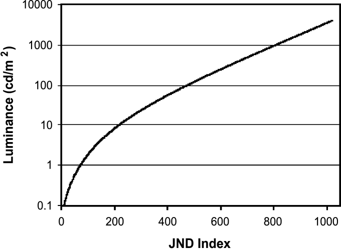
To ensure that as much information as possible can be seen by the human eye, display systems should be set to the Digital Imaging and Communications in Medicine (DICOM) 14 Grayscale Standard Display Function (GSDF) (see Fig 1). This is necessary because the response of the human eye to light is not linear. This step is achieved by mapping bit values representing different gray levels to specific luminance values. The mapping is stored in look-up tables (LUT) on the graphics card or in the monitors.
Fig 1.
DICOM 14 Grayscale Standard Display Function (GSDF). The Just Noticeable Difference (JND) index is the minimum amount that the luminance can be changed for the human eye to perceive a difference.
Visual Checks
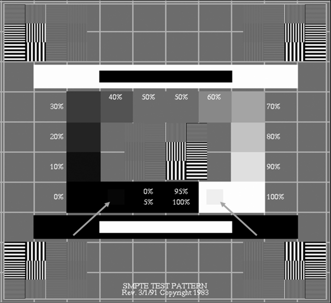
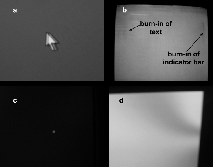
The final step is a visual check. There are several geometric patterns and patterns of varying luminosity that can be helpful. One that is often used is the Society of Motion Picture and Television Engineers (SMPTE) pattern (see Fig 2). This pattern can be used to detect areas that are unfocused (horizontal and vertical thin lines that should be discernable) and to determine the proper contrast (especially the 0 to 5% luminance difference and the 95 to 100% luminance difference). The SMPTE pattern can also be used to align the window vertically and horizontally and to determine if there is skewing or bowing (pincushion effect). Other parameters to check include ghosting (i.e., when previous images linger), burn-in on CRT monitors, pixel dropout in LCD monitors, and nonuniformity of luminance (see Fig 3). Uniformity of luminance can be measured by placing the photometer on different quadrants of the monitor. Luminance nonuniformity is usually not a problem with LCD monitors, but can be a problem with CRT monitors. This can occur if the CRT phosphor coating is not applied evenly, if the phosphor on the edges of the screen gets less light than in the middle of screen due to the distorted electron beam, or if there is a misalignment in the CRT components. Nonuniformity is also prevalent in CRT monitors that are within a magnetic field.
Fig 2.
SMPTE pattern: Left arrow indicates a 5% luminance square inside a larger 0% luminance square. Right arrow indicates a 95% luminance square inside a larger 100% luminance square. Copyright SMPTE, used with permission.
Fig 3.
Examples of monitors showing (a) ghosting, (b) burn-in, (c) pixel dropout (magnified), and (d) nonuniformity of luminance.
Monitor Calibration Pilot Study
A variety of clinical and radiological Picture Archiving and Communication Systems (PACS) workstations from a multisite teaching hospital were identified for use in a pilot study for the protocol. The purpose of the pilot study was (1) to determine the value of a monitor quality control program through an assessment of their current state and noting any improvements after application of the protocol, (2) to validate and if necessary, to modify the protocol, and (3) to determine the resource requirements to perform the quality control program.
Sixteen PACS workstations (11 dual-monitor systems and 5 single-monitor systems) were calibrated during the study. Three of the workstations were intentionally included for the pilot due to complaints of poor image quality, whereas the other workstations were randomly chosen out of approximately 1,000 workstations that are used for viewing medical images. They were selected from radiology reading rooms and clinics to represent a range of monitor types.
Results
Four monitors out of the 27 monitors tested were found to be inadequate for medical image review even after calibration. The monitors were inadequate because either the maximum luminance for these monitors were about 90 cd/m2, which was much lower than the ideal maximum luminance of 170 cd/m2 for color monitors, or the monitors were visibly unfocused. In addition, the calibration photometer was not able to connect to two workstations, which had computers that were nonstandard to the hospital and were not supported by the hospital IT department. Both of the workstations had monitor quality deemed inadequate for image review and have been excluded from the following results summary.
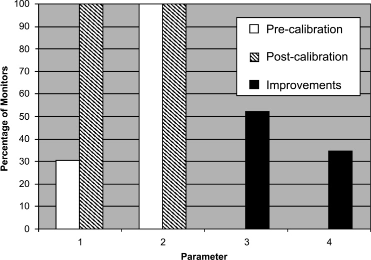
Most monitors showed significant image quality improvements from calibration (Fig 4). Before calibration to the GSDF, on approximately 70% of the monitors, the difference between 0 and 5% luminance could not be seen on the SMPTE pattern. After calibration, this difference was discernible on all the monitors. The maximum luminance and dark levels were often adjusted to prolong longevity of the monitors while trying to optimize image quality. Other image-quality-degrading factors that were found include areas that are unfocused, phosphor burn-in from a static image (hospital logo used as the Windows desktop wallpaper) left on the monitor too long, incorrectly set aspect ratios, and dirty screens.
Fig 4.
Image quality improvements through calibration. 1, Monitors able to discern between 0 and 5% luminance values; 2, monitors able to discern between 95 and 100% luminance values; 3, monitors with maximum luminance not optimally set (difference between calibrated and original values >10 cd/m2); 4, monitors with dark levels not optimally set (difference between calibrated and original values >0.2 cd/m2).
It took on average 30 min to calibrate a display system by a trained technician with limited experience performing the protocol. An experienced technician could calibrate a display system in about 15 min.
Discussion
Maintenance of Image Quality
Initial calibration and periodic testing of PACS monitors are important for maintenance of image quality. A degradation of image quality over a long time is often difficult for clinicians to detect. This can result in a delay in reporting of problems until the viewing of the images is severely degraded by the display.
The frequency of calibration and testing can vary greatly. Hospitals have performed weekly, quarterly, or even daily monitor tests, whereas others do not calibrate monitors at all.12 The proper frequency of calibration depends on how quickly the monitor changes over time, such as becoming unfocused. The maximum luminance and dark level also changes over time (known as drift). The severity of drift varies between monitor models, and the acceptability of the drift is dependent on the application of the monitor. It would be reasonable to check the image quality of diagnostic workstations (e.g., in Radiology, some workstations in the Emergency Department and Fracture Clinic) at least once a week or every 2 weeks, until the trend of the drift is discovered. For PACS workstations that are used for clinical reference only, it may be only required to perform an image quality check monthly or biannually and then reassess the frequency by the drift trends.
If the drift of the monitor becomes too severe (e.g., maximum luminance drops too low) and it cannot be corrected, the monitor should be repaired or replaced. Setting the maximum luminance properly will not only help ensure adequate image quality, but it will also prolong the useful life cycle of the monitor.
In addition to the methods described above, the following are other means to facilitate the maintenance of image quality:
The use of a maintenance database to record calibration results, age, warranty, location, etc. of the PACS monitors would provide several benefits. For example, it would allow a convenient method of scheduling monitor maintenance.
Disabling user control of the display settings and training the users to modify window and leveling in the PACS viewer application instead of changing the monitor contrast and brightness will also help reduce the frequency of required calibration.
Procedures for escalation and maintenance of PACS display systems should be streamlined. This would include clarifying who is first-line support and having backup hardware on-site.
Environmental factors, such as ambient room lighting, glare, and placement of the monitor ateye level, should also be considered for optimizing medical image viewing.13,14 It is particularly important to horizontally and vertically center LCD monitors with reference to the users' line of sight to keep the image from appearing distorted. Antireflection treatments might also be appropriate depending on the environment.
Clinical Relevance
Precalibration, clinicians had complained about the inadequate image quality of some of the monitors that were calibrated for this study. After calibration or replacement of the monitors, the clinicians no longer complained about the image quality. This suggests that the clinicians did notice the postcalibration improvements. An in-depth investigation into the clinical perception of the image quality improvements from calibration was outside the scope of this study.
Hardware Selection
Adding to the complexity of ensuring adequate image quality is choosing the proper supporting hardware (monitors, computers, and graphics cards). Although standardizing on a single vendor of PACS hardware can assist in the maintenance of the equipment, it is often difficult to achieve in practice because of financial constraints and/or the need to select different monitors for different applications. Space requirements might dictate theuse of an LCD monitor instead of the larger CRT monitor. The once prohibitively high cost of high-bright grayscale LCD monitors is becoming less of a problem as the cost of LCD monitors continually drop, whereas concurrently, the advancements in LCD technology lead to increasingly better image quality.
CRT and LCD monitors have their own strengths and weaknesses, but more institutions are moving from using CRT monitors to LCD monitors. Table 1 summarizes their characteristics.
Table 1.
Comparison between CRT and LCD monitors
| Characteristic | CRT | LCD |
|---|---|---|
| Cost | – | X (–) |
| Space requirements/weight | X | ✓ |
| Power consumption | ✓ | – |
| Brightness | ✓ | ✓ |
| Contrast | ✓ | – |
| Focus | – | ✓ |
| Geometry | – | ✓ |
| Adjustment of resolution | ✓ | X |
| Color quality | ✓ | – |
| Flickering | X | ✓ |
| Magnetic field distortions | X | ✓ |
| Response time | ✓ | – |
| Pixel dropout (pixel always on or off) | ✓ | X |
| Burn-in | X | ✓ |
X represents a con, ✓ represents a pro, and – represents a neutral characteristic.
The type of images that will be viewed on the PACS workstation will also influence the monitor selection and computer configuration. Here are some questions that need to be asked when developing a display system.
Are the images monochrome or in color? The trade-off of color monitors is that they cannot achieve the level of luminance of grayscale monitors.
Are the images high-resolution and high-contrast (e.g., computed radiography) or low-resolution and low-contrast (e.g., magnetic resonance imaging) images? This will determine the required monitor resolution and the suitability of using grayscale monitors.
What is the volume of images that will be viewed on the PACS workstation? Are the images stacked (e.g., stacked computed tomography images). This will determine the computer requirements, such as processor speed, random access memory (RAM), and hard drive space.
Is the display system going to be used for primary diagnosis or for a clinical review? Are the structures that need to be identified gross structures (e.g., metal leads that were inserted into the body) or small, hard to discern structures (e.g., in mammography images)? This will influence several decisions regarding hardware selection, including the required bit depth of the graphics card. Most graphics cards are 8-bit digital to analog converters (DAC) allowing 256 levels of intensity for each red, green, and blue channel, but often higher-bit depth cards are preferable (10-bit cards) for monochrome monitors.
Will past and current images of the same patient need to be compared side by side? Will multiple views of the anatomy need to be viewed simultaneously? If so, then dual monitors will likely be required. In this case, care must be taken in choosing a graphics card that has two LUTs so that both monitors can be calibrated to the DICOM GSDF. Most graphics cards, especially the less expensive ones, do not have dual LUTs, which means that only one monitor can be calibrated.
It is also beneficial to obtain clinical feedback on the type of PACS workstation hardware that will be put into a particular unit. Unfortunately, this is often not done due to time constraints or lack of available hardware. Whenever possible, demo units should be trialed to obtain clinical feedback before the hardware is purchased. This should be done for several days to give all the staff adequate opportunity to use the equipment and to provide verbal or written feedback on a survey form.
Future Trends
Several medical display manufacturers are starting to develop methods to help achieve and maintain stable image quality. Many high-end monitors are now strictly factory-calibrated for medical viewing. There are also LCD monitors available that do periodic self-calibration with an internal backlight sensor or with a permanent photometer on the corner of the monitor. Unfortunately, these are usually very expensive high-end monitors.15 Besides the high cost of self-calibrating monitors, there are image quality problems that they cannot detect, such as pixel dropout, dirty screens, and improper resolution settings.
Remote calibration is also emerging as an option, whereby PACS workstations are connected to a main administrative computer. The main administrative computer receives alerts of monitor drift that cannot be compensated, and it can trigger the computers to do self-calibrations. Remote calibration, however, has some of the same problems as the self-calibration monitors. Presently, remote calibration requires all of the monitors to be of a single brand. Standardizing onto a single high-end monitor brand would be prohibitively costly and impractical for most institutions.
Conclusions
The proliferation of PACS has permitted the softcopy review of medical images outside, as well as within, the radiology department. Although the selection of proper display system hardware will vary depending on the application and the environment, maintaining proper image quality should always be a consideration for the system's ongoing use. This is often a difficult program to establish and maintain due to limited human and financial resources, the large number of display systems that are often nondedicated standard desktop computers and monitors, and the lack of comprehensive standards.
It has been shown through the pilot of a monitor quality assurance protocol that a proactive calibration program can ensure adequate image quality. An inexpensive method of monitor calibration has been described that can be applied to any type of monitor. Substantial image quality improvements were seen postcalibration, and monitors that were no longer adequate for medical image display were identified and replaced. The use of an image quality maintenance protocol will lead to more efficient image review and more accurate diagnoses.
References
- 1.Compton K, Hemminger BM, Oosterwijk H. Practical usage of image quality verification tools. Proc SPIE. 2001;4323:148–150. doi: 10.1117/12.435469. [DOI] [Google Scholar]
- 2.http://www.aapm.org/
- 3.http://www.hpa.org.uk/
- 4.http://www.sst.dk/upload/nrpa_report_nr_7_001.pdf
- 5.http://www.ccachiro.org/client/CCA/CCAWeb.nsf/web/4Chapter?OpenDocument
- 6.Mertelmeier T, Scharl P. Acceptance testing for soft copy displays. Proc SPIE. 2001;4319:525–535. doi: 10.1117/12.428096. [DOI] [Google Scholar]
- 7.Wang J, Peng Q. An interactive method of assessing the characteristics of softcopy display using observer performance tests. J Digit Imaging. 2002;15(Suppl 1):216–218. doi: 10.1007/s10278-002-5003-3. [DOI] [PubMed] [Google Scholar]
- 8.Wang J, Compton K, Peng Q. Proposal of a quality-index or metric for soft copy display systems: contrast sensitivity study. J Digit Imaging. 2003;16(2):185–202. doi: 10.1007/s10278-003-1657-8. [DOI] [PMC free article] [PubMed] [Google Scholar]
- 9.American Association of Physicists in Medicine (AAPM), Task Group 18. Assessment of Display Performance for Medical Imaging Systems: Pre-final Draft (Version 8.1), February 2002
- 10.Gray JE, Lisk KG, Haddick DH, Harshbarger JH, Oosterhof A, Schwenker R. Test pattern for video displays and hard-copy cameras. Radiology. 1985;154:519–527. doi: 10.1148/radiology.154.2.3966138. [DOI] [PubMed] [Google Scholar]
- 11.Steven PM: Monitor Calibration and Image Integrity. RSNA Categorical Course in Physics. RSNA, Oakbrook, IL, 1996, pp 207–212
- 12.Parsons DM, Kim Y, Haynor DR. Quality control of cathode-ray tube monitors for medical imaging using a simple photometer. J Digit Imaging. 1995;8(1):10–20. doi: 10.1007/BF03168051. [DOI] [PubMed] [Google Scholar]
- 13.Chakrabarti K, Kaczmarek RV, Thomas JA, Romanyukha A. Effect of room illuminance on monitor black level luminance and monitor calibration. J Digit Imaging. 2003;16(4):350–355. doi: 10.1007/s10278-003-1720-5. [DOI] [PMC free article] [PubMed] [Google Scholar]
- 14.Ratib O, Amato C, Balbona JA, Boots K, McCoy JM. Design and implementation of a multi-task radiology workstation ergonomically tailored for fully digital reading rooms. Proc SPIE. 2001;4323:93–96. doi: 10.1117/12.435461. [DOI] [Google Scholar]
- 15.Blume H, Ho AMK, Stevens F, Steven PM. Practical aspects of greyscale calibration of display systems. Proc SPIE. 2001;4323:28–41. doi: 10.1117/12.435509. [DOI] [Google Scholar]


