

Abstract
The combination of sensitive magnetic resonance techniques with a selective site-targeted nanoparticle contrast agent has a demonstrated utility for molecular imaging studies. By detecting a unique signature of the contrast agent, this approach can be employed to identify specific bio-molecular markers and observe cellular-level processes within a large and complex organism (e.g., in vivo rabbit). The objective of the present investigation was to design, fabricate and characterize a radio-frequency (RF) coil for the dual frequency (1H and 19F) simultaneous collection of both nuclei images in a 3T field, in order to facilitate studies of arthritic knee degradation in rabbits. The coil supports both transmit and receive modes. The supporting activities included: 1) establishing a technical database for calculating the required coil parameters, 2) selection of a favorable coil geometry, and 3) adaption of existing RF measurement techniques to the design, development and electrical evaluation of the coil. The coil is used in conjunction with a Philips Medical Systems clinical MRI scanner, requiring all RF simultaneous dual frequency (1H and 19F) coils to operate in both transmit and receive modes. A commercial version of SPICE (simulation program with integrated circuit emphasis) was used to estimate significant operational parameters prior to fabricating the imaging coil. Excellent images were obtained with the fabricated coil and no operational problems were observed that would limit the use of other coil geometries and field strengths.
Keywords: Fluorine imaging, magnetic resonance imaging (MRI), multifrequency, radio-frequency (RF) coil design, targeted nanoparticle contrast agent
I. Introduction
FLUORINE (19F) magnetic resonance (MR) permits the detection and quantification of fluorine-labeled tracers and drugs in the field of molecular imaging [1]. Due to the small amounts of endogenous fluorine, a typical approach to fluorine imaging combines registration of the anatomical object with 1H scans with subsequent fluorine (19F) spectroscopy or images to provide the required information. There are two common and significant issues with this approach: first, the image registration between scans of the two different nuclei can change due to coil and specimen manipulation; and second, with retuning and matching adjustments for fluorine, the sensitivity profiles of the imaging coil at the two corresponding frequencies vary. Furthermore, the use of a single tuned radio-frequency (RF) probe with sufficient bandwidth to accommodate both nuclei would significantly increase the receiver noise figure, reducing the received signal sensitivity and limiting the receiver’s dynamic range [2]. The feasibility of employing a tuned and matched dual-frequency coil that collects both 1H and 19F images simultaneously has been reported for an enclosed solenoid geometry in a 3T field, by researchers at Philips Research [3]. Considering the operational constraints imposed by size and access requirements of the rabbit knee to be evaluated, the present work extends the dual-frequency coil simultaneous image concept to include a double-tuned circuit with an input parallel resistor, inductor, and capacitor (RLC) auxiliary resonant circuit in series with an open coil design based on a geometry proposed by Ballon, et al. [4] and Jin et al. [5]. The open coil design allows the cylindrical shape and multiple loops, with current steering similar to a birdcage design, to provide a larger coil volume with enhanced B1 field uniformity while maintaining adequate sensitivity to support transmit and receive imaging of a rabbit at both 1H and 19F nuclei.
II. Theory
Designed for operation in a 3T magnetic field, the corresponding resonant frequencies of the target 1H and 19F nuclei are 127.78 MHz and 120.28 MHz, respectively. The theoretical basis for the subject dual frequency coil described herein is the so-called “double tuned” circuit, in our case containing two RLC resonators, the first a parallel RLC auxiliary resonant circuit series coupled to an open coil RLC semi-birdcage configuration. The double tuned circuit has been used extensively in RF design and is described in the literature; [6] and [7] contain a thorough description and analysis of this circuit design. For our application, two such resonant circuits, tuned to the same frequency of 127.8 MHz (1H nuclei) are coupled through a capacitor that is small in comparison to the individual resonator tuning capacitance. Keeping the individual resonators tuned to 127.8 MHz, and loosely coupled, with a very small capacitance, only one resonant peak is obtained. If the coupling is increased to the critical coupling value, by increasing the coupling capacitor size, the resonant peak broadens and flattens at the resonant frequency, again at 127.8 MHz. Increasing the coupling capacitor size above the critical coupling value produces two resonant peaks, with one at 127.8 MHz and the other at a slightly lower frequency with their separation now determined by the coupling capacitor value. This is a significant feature that must be kept in mind while analyzing the two-coil tuning operation, i.e., the primary resonance is due to the fact that both resonators are tuned to 127.8 MHz and the second resonant peak is solely determined by varying the resonator-to-resonator capacitive coupling. The open coil’s (second resonator) lower mode frequencies have no significance in determining the dual-frequency (1H and 19F) coil’s frequency response.
III. Materials and Methods
A. Input Parallel RLC Auxiliary Resonant Circuit
This resonator is shown in schematic form in Fig. 2(a) as part of the SPICE simulation diagram and consists of L1, C1, and R1. One can observe L1 and C1 in the Fig. 4 (inset). For the dual-frequency coil, the components for tuning and matching of both resonators are all located on the input resonator assembly. The inductor L1 is a toroidal coil using an Amidon coil form T50-6 with 4 turns and C1 is an American Technical Ceramics (ATC) 10 picofarad (pf) 2400 VDC chip capacitor. The coupling capacitors identified as C3A and C3B are in series providing a balanced configuration as are matching capacitors C4A and C4B with both configurations shown in Fig. 2(a). They are physically identified in Fig. 4(a) (inset). A tuning variable capacitor is included in parallel with C1 to insure the input auxiliary resonator is tuned to exactly 127.8 MHz. In addition to the components discussed so far, three additional variable capacitors are included on this assembly, one in parallel with capacitor C4A for input matching, one in parallel with C2 to insure the open coil is tuned to exactly 127.8 MHz, and one in parallel with capacitor C3A to provide variable resonator-to-resonator coupling to insure the second dual-frequency of 120.2 MHz is established.
Fig. 2.

The dual-frequency coil is conceptualized as two separate LCR resonators (L1, C1, R1) and (L2, C2, R2) electrically coupled via capacitor C3. Panel (a) shows the equivalent circuit diagram and panel (b) illustrates the impedance magnitude output of a SPICE simulation of two capacitively coupled resonators.
Fig. 4.
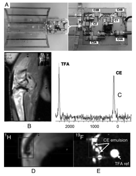
(A) Photograph of completed dual-frequency coil and supporting electronics. The 6-leg (5-loop) coil structure is shown in the upper left portion of the image. Inset figure depicts a close-up image of the supporting electronics (B) High-resolution 1H image of arthritic rabbit knee showing highlighting anatomic features. (C) Spectral lines corresponding to the measured fluorine resonance from crown ether (perfluoro-15-crown-5-ether; CE) emulsion and trifluoracetic acid (TFA) reference standard. Simultaneously acquired 1H and 19F images of the rabbit knee post injection of the CE emulsion, (D) and (E), respectively.
B. Open Coil Fabrication
The implemented coil geometry is composed of five rectangular conducting loops, mapped onto the surface of a semi-circular cylinder. For the convenience of description, we use the word “leg” to represent the parallel lateral conductors on the cylindrical surface and use the word “end-ring” to denote the end loop containing capacitors. Each of these individual loops (length:width aspect ratio of 4:1) is conjoined to its neighbors, along the long edge, sharing a conducting “leg” as shown in the circuit diagram shown in Fig. 1(a). Combined with the intrinsic inductance of the conducting material, electrical resonance properties are constructed by inserting discrete capacitive elements into the short “end-ring” of each loop. Derivation of a circuit analysis, to describe the operation of this type of open coil design, can be accomplished by solving the appropriate system of Kirchhoff’s loop equations [8]. For the high-pass configuration employed, the resonant mode-frequencies for the open coil, ωm, can be expressed as follows (see [9, eq. 4.47])
| (1) |
Fig. 1.

Simulation of response for six-leg (five-loop) open coil design. (a) Circuit diagram, defined using SPICE, for 140° arc length open coil and (b) the corresponding 129.4 MHz fundamental mode frequency.
Here Ler is the “end-ring” inductance, Lleg is the “leg” inductance, m is the mode number, N is the number of loops in the coil, and C is the equivalent total “end-ring” capacitance, distributed around the coil circumference. Given the desired resonance frequency and the known circuit properties, this equation can be inverted to solve for the required capacitor value.
The high-pass open coil design was fabricated using copper strip conductors and discrete surface mount capacitors adhered to the outside of a curved support structure. The channel-shaped support was fashioned from a 15-cm-long Lucite (polymethyl methacrylate) cylinder with an outer diameter radius of 7.1 cm and a uniform 140° arc cross section [7]. Adhesive backed copper tape (0.64 cm width, 3M, St. Paul, MN) was cut and patterned to form the five coil loops, consisting of six 14.7-cm-long legs with 3.5 cm end-ring spacing. The low frequency inductances of these individual legs and end-rings were calculated to be 127.5 nH and 20.3 nH, respectively.
The mutual inductance effect on coil resonance is dominated by the mutual inductance among the open-coil legs. However, due to the incomplete symmetry of the open-coil design, the mutual inductance is slightly different for the different coil loops. To include the leg-to-leg mutual inductance and the small (5%) “end-ring”-to-“end-ring” mutual inductance effects, a SPICE [10] circuit diagram was defined as depicted in Fig. 2(a). The open coil simulation output fundamental mode resonant response is shown in Fig. 1(b), where the voltage is developed across one of the leg load resistances R16. As observed from Fig. 1(b), the response curve is for a narrow band of frequencies. As expected, increasing the frequency sweep would show the lower modal frequencies of 54.9 MHz and 71.4 MHz. However, these two frequencies have no affect on the dual-coupled resonator response since the two nuclei frequencies are in such close proximity and the presence of the input parallel auxiliary RLC circuit prevents the lower mode frequencies from reaching the open coil. The modal frequencies could be of possible concern if we were dealing with nuclei that had an effective large fractional bandwidth.
Electrical measurement of the S21 transmission parameter was performed on the completed open-coil, using a network analyzer (Hewlett Packard 8751A) in conjunction with a pair of 3.5 cm circular-loop shielded probe coils. These probe coils had a prescribed overlap to provide optimal coil-to-coil isolation [11], that was equal-to or greater-than 50 dB over a frequency bandwidth from 110 to 150 MHz. The dual frequency coil measurements were made using the probe coils described previously. The dual frequency coil unloaded values, QU, were 308 and 290 at 120.2 MHz (19F) and 127.8 MHz (1H), respectively. The loaded values of the dual frequency coil were determined using the rabbit phantom. The dual frequency coil loaded values, QL, were 122 and 114 at 120.2 MHz (19F) and 127.8 MHz (1H), respectively. Although these quality factors, Q, represent good coil efficiency, Doty, et al. [13] cautions that the common coil-quality metric QU/QL is often misleading for surface coils and that more importantly, performance is significantly degraded if the space between the sample and the coil is suboptimal (i.e., the liftoff effect [14]).
C. Capacitive Coupled Resonator Fabrication
The terminal characteristics of the fabricated open coil, measured using a network analyzer (HP-8751A) at the 1H frequency of 127.78 MHz, yielded an equivalent parallel inductance [L2 Fig. 2(a)] of 47 nanohenries (nH) shunted with the calculated highpass “end-ring” capacitance of 33 pF. Using these complex impedance values, the input RLC auxiliary resonator circuit was constructed to operate at the 1H frequency of 127.78 MHz, i.e., the two resonators have equal electrical component values with different mechanical characteristics. Again, the two resonators will be tuned to the same frequency of exactly 127.78 MHz (1H at 3T). The expression, given by (2), was derived (see Appendix A) to determine the coupling capacitor value of 2.0 pF, for 1H and 19F
| (2) |
IV. Electrical Simulation and Image Results
Based on the values measured on the isolated open coil and the value of the required coupling capacitor, a SPICE simulation schematic was defined for the dual-frequency coil. This circuit diagram, represents the two coupled resonators, one being the Thévenin equivalent parallel RLC of the open coil (right) and the second resonator the auxiliary input resonator provided by the parallel RLC circuit (left), as detailed in Fig. 2(a). The simulation is driven by a 50Ω, 1 Amp ac current source so that the input impedance sweep will register 25Ω at the dual resonance points. The corresponding graph is shown in Fig. 2(b).
After the dual frequency 1H and 19F coil was fabricated, initial electrical measurements were made on the coil using a rabbit phantom for loading purposes. This phantom consisted of a glass specimen container filled with 0.5% trifluoracetic acid (TFA) in 0.1M NaCl with a lateral length of 13 cm and a diameter of 6 cm. An electrical calibration was made of the phantom relative to a rabbit load prior to making electrical measurements. Measurements of the parameter S11 were made using a network analyzer (HP 8751A). Fig. 3(a) relates the magnitude of the return loss, and Fig. 3(b) displays the frequency dependent complex S11 quantity on a Smith chart. Only two spectral lines at 120.2 MHz and 127.8 MHz are observed since the input parallel RLC auxiliary resonant circuit, due to its characteristic operation, will not pass the open coil lower mode frequencies.
Fig. 3.

Simultaneous dual-frequency return loss (S11) of open-coil measured using network analyzer with rabbit phantom load. Return loss, better than −30 dB, is observed at both of the tuned 1H (120.2 MHz) and 19F (127.8 MHz) resonant frequencies.
The completed dual-frequency (1H, 19F) coil is shown in Fig. 4(a). In this image, the open-coil is on the left, the auxiliary resonator is in the middle, and a RG-174 (Belden) coaxial cable with a BNC connector is towards the right end of the picture. A nonmagnetic resonate trap (not shown), consisting of five-turns of RG-174 coaxial cable wound around a 1.3 cm toroidal core and paralled with a chip capacitor value for resonance at 124 MHz, connects the RG-174 coaxial cable to a single custom research RF BNC coaxial interface of a 3.0T clinical MR scanner (NT Achieva CV, Philips Medical Systems).
The experimental protocol was approved by the Animal Studies Committee of the Washington University School of Medicine. The rabbit was anesthetized with ketamine/xylazine (30 mg/kg, 6 mg/kg; intramuscularly) for an intra-articular injection of 100 μl perfluoro-15-crown-5-ether emulsion (CE) in the knee joint. Immediately following the injection, the sedated rabbit was positioned in the MR scanner with the knee placed in the center of the coil and raised to isocenter in the coronal plane.
Standard proton density weighted images, shown in Fig. 4(b), were acquired to obtain high-resolution 1H anatomic images with the dual tuned coil. Volume selective MR spectroscopy of the injection region was also performed in order to quantify the fluorine signal. A tube filled with trifluoracetic acid (TFA) was placed within the field-of-view and served as a signal intensity reference standard. Measured spectral lines of CE and TFA are displayed in Fig. 4(c). In both the spectroscopy and imaging results, the CE signal intensity is comparable to that of the 300 μl TFA reference.
To validate the functionality of the implemented coil design, dual-frequency data were acquired simultaneously. MR images of the arthritic rabbit knee, constructed from the 1H for signal anatomic detail [Fig. 4(d)] and the 19F signal for tracking the injected emulsion [Fig. 4(e)] are shown. The dual frequency images were acquired using a Philips Medical Systems 3T Achieva CV Scanner adapted to provide simultaneous 1H and 19F nuclei transmit and receive capability. The dual frequency coil is tuned and matched prior to insertion into the scanner. Slight retuning is required once the coil is inserted into the scanner. No further adjustments are then required for the duration of scanning.
V. Conclusion
In this manuscript, we have presented the design, characterization, and assessment of an open RF coil used in conjunction with a coupled second auxiliary resonator to provide simultaneous dual frequency (1H and 19F) imaging at 3T. A unique strength of this design is the ability to image both anatomy (1H) and exogenous contrast (19F) truly simultaneously, eliminating the chance for image registration problems while maximizing throughput. SPICE electronic modeling aided the design and selection of coil components through simulation prior to coil fabrication. The ultimate fundamentals of this coupled-resonator coil are applicable to other coil geometries and useable beyond 3T field strengths.
Acknowledgments
This work was supported by the U.S. National Institutes of Health under Grant CA119342 (GML), Grant HL073646 (SAW), and Grant AR056468 (CTP).
APPENDIX
A simplified network schematic corresponding to the double-tuned circuit is represented in Fig. 2(a). The two parallel RLC resonators (R1, L1, C1 and R2, L2, C2 where R1 = R2 = R, L1 = L2 = L and C1 = C2 = C) are coupled via a capacitor, and C3.
Using Thévenin’s theorem after the procedure discussed in [8], the circuit analysis consists of finding the transfer impedance
| (A1) |
where the s-operator facilitates equation manipulations. The double-tuned circuit is divided into two sections by removing C3, the coupling capacitor. Denoting the impedance of the parallel RLC as
| (A2) |
where, α = 1/(2RC), and ω = 1/(LC).
We now define the Thévenin open circuit voltage Eoc as
| (A3) |
The coupling current Im, for the double-tuned circuit, is the current division ratio of Im to I1 as
| (A4) |
Hence,
| (A5) |
And substituting Z for from (A2) into (A5)
| (A6) |
Guillemin [8] expresses the second quadratic in the denominator of (A6) as
| (A7) |
where, β = α/(1 + 2C3/C) and
| (A8) |
Knowing the resonator capacitance, C and the two frequencies, fα and fβ, the following expression, for the coupling capacitor (C3) value, is derived by repeated use of Taylor expansions to obtain the required dual frequencies.
From (A8) .
Or
Therefore, for 1H and 19F at 3T
| (A9) |
Contributor Information
Franklin D. Hockett, Department of Medicine, Cardiology Division, Washington University School of Medicine, St. Louis, MO 63110 USA.
Kirk D. Wallace, GE Global Research, Niskayuna, NY 12309 USA..
Anne H. Schmieder, Department of Medicine, Cardiology Division, Washington University School of Medicine, St. Louis, MO 63110 USA.
Shelton D. Caruthers, Department of Medicine, Cardiology Division, Washington University School of Medicine, St. Louis, MO 63110 USA..
Christine T. N. Pham, Department of Medicine, Rheumatology Division, Washington University School of Medicine, St. Louis, MO 63110 USA.
Samuel A. Wickline, Department of Medicine, Cardiology Division, Washington University School of Medicine, St. Louis, MO 63110 USA..
References
- [1].Morawski AM, Winter PM, Yu X, Fuhrhop RW, Scott MJ, Hockett F, Robertson JD, Gaffney PJ, Lanza GM, Wickline SA. Quantitative magnetic resonance immunohistochemistry with ligand-targeted (19)F nanoparticles. Magn. Reson. Med. 2004 Dec.vol. 52:1255–62. doi: 10.1002/mrm.20287. [DOI] [PubMed] [Google Scholar]
- [2].Kumar A, Edelstein WA, Bottomley PA. Noise figure limits for circular loop MR coils. Magn. Reson. Med. 2009 May;vol. 61:1201–9. doi: 10.1002/mrm.21948. [DOI] [PMC free article] [PubMed] [Google Scholar]
- [3].Mazurkewitz PC, Leussler C, Keupp J, Schaeffter T. A double-resonant 19F/1H transmit/receive solenoid coil for MRI. Proc. Int. Soc. Mag. Reson. 2006;vol. 14:2596. [Google Scholar]
- [4].Ballon D, Graham MC, Miodownik S, Koutcher JA. A 64 MHz half-birdcage resonator for clinical imaging. J. Magn. Reson. 1990;vol. 90:131–140. [Google Scholar]
- [5].Jin J, Magin RL, Shen G, Perkins T. A simple method to incorporate the effects of an RF shield into RF resonator analysis for MRI applications. IEEE Trans. Biomed. Eng. 1995 Aug.vol. 42:840–3. doi: 10.1109/10.398645. [DOI] [PubMed] [Google Scholar]
- [6].Hayward WH. Introduction to Radio Frequency Design. Prentice-Hall; Upper Saddle River, NJ: 1982. [Google Scholar]
- [7].Mispelter J, Lupu M, Briguet A. NMR Probeheads for Biophysical and Biomedical Experiments. Imperial College; London, U.K.: 2006. [Google Scholar]
- [8].Guillemin EA. Introductory Circuit Theory. Wiley; New York: 1953. [Google Scholar]
- [9].Jin J. Electromagnetic Analysis and Design in Magnetic Resonance Imaging. 1st ed CRC Press; Boca Raton, FL: 1998. [Google Scholar]
- [10].B2 Spice. ver. 5 Beige Bag Software; Ann Arbor, MI: [Google Scholar]
- [11].Roemer PB, Edelstein WA, Hayes CE, Souza SP, Mueller OM. The NMR phased array. Magn. Reson. Med. 1990;vol. 16:192–225. doi: 10.1002/mrm.1910160203. [DOI] [PubMed] [Google Scholar]
- [12].Nye W, Riley DC, Sangiovanni-Vincentelli AL, Tits AL. DELIGHT.SPICE: An optimization-based system for the design of integrated circuits. IEEE Trans. Computer-Aided Design Integr. Circuits Syst. 1988 Apr.vol. 7(no. 4):501–519. [Google Scholar]
- [13].Doty FD, Entzminger G, Kulkarni J, Pamarthy K, Staab JP. Radio frequency coil technology for small-animal MRI. NMR Biomed. 2007;vol. 20:304–25. doi: 10.1002/nbm.1149. [DOI] [PubMed] [Google Scholar]
- [14].Suits BH, Garroway AN, Miller JB. Surface and gradiometer coils near a conducting body: The lift-off effect. J. Magn. Reson. 1998;vol. 135:373–9. doi: 10.1006/jmre.1998.1608. [DOI] [PubMed] [Google Scholar]