Abstract
A tetrode is a bundle of four microwires that can record from multiple neurons simultaneously in the brain of a freely moving animal. Tetrodes are usually electroplated to reduce impedances from 2-3 MΩ to 200-500 kΩ (measured at 1 kHz), which increases the signal-to-noise ratio and allows for the recording of small amplitude signals. Tetrodes with even lower impedances could improve neural recordings but cannot be made using standard electroplating methods without shorting. We were able to electroplate tetrodes to 30-70 kΩ by adding polyethylene glycol (PEG) or multi-walled carbon nanotube (MWCNT) solutions to a commercial gold-plating solution. The MWCNTs and PEG acted as inhibitors in the electroplating process and created large-surface-area, low-impedance coatings on the tetrode tips.
Keywords: Tetrodes, electroplating, carbon nanotubes, impedance, extracellular recording
Introduction
The tetrode, a bundle of four microwires, is an important tool for neuroscience research because it can be used to isolate signals from multiple neurons in the brains of freely moving animals [1, 2, 3, 4]. The impedances of tetrodes can greatly affect the quality of neural recordings [5, 6]; high-impedance electrodes are associated with increased thermal noise and signal loss to shunt pathways [7, 8]. In order to reduce impedances, tetrodes are usually electroplated with gold or platinum.
Electroplating causes the deposition and growth of crystallites on the tips of tetrode microwires, increasing their effective surface areas and lowering their impedances. However, excessive electroplating of a tetrode can cause the crystallites on one microwire to grow too much and touch the crystallites on the other microwires, causing a short. Usually, tetrodes made from 10-to-30-μm diameter wires are plated to moderate impedance levels of 200 to 500 kΩ (at 1 kHz) because plating to below 100 kΩ results in shorting.
Tetrode recordings may benefit from a new method to lower impedances even further, allowing for the isolation of small-amplitude signals that were previously hidden by thermal noise or lost to shunt pathways, thereby enhancing sensitivity without sacrificing selectivity. Several innovative methods have been developed to lower microelectrode impedances, including the use of conductive polymers [8], titanium nitride [9], iridium oxide [10], and roughened polysilicon [11]. However, these methods have not been tested on tetrodes and would be difficult for most neurophysiologists to recreate in their own labs without acquiring expensive new equipment. A more practical alternative would be to modify the standard electroplating process most neurophysiologists currently use. Cui and Martin [12] showed that altering the concentration of gold-plating solution and electroplating current can change the morphology of a gold-plated microelectrode coating. Additionally, Keefer et al. [13] found that adding multi-walled carbon nanotubes (MWCNTs) to a gold-plating solution created microelectrode coatings with a “rice-like” texture and very low impedances.
In this paper, we combine and expand upon the methods of Cui and Martin [12] and Keefer et al. [13] and investigate how to create low-impedance coatings for tetrodes. We start by examining tetrode coatings produced using various gold-plating solution concentrations and electroplating currents. Then, we explain how we made tetrodes with the “rice-like” texture described by Keefer et al. [13] using MWCNTs and made tetrodes with a similar texture using an additive not discussed in Keefer et al. [13], polyethylene glycol (PEG). Additionally, we describe a new coating with a very large surface area (made with MWCNTs or PEG and a low electroplating current) that consistently lowered the impedances of tetrodes to 30 kΩ to 70 kΩ without shorting. Finally, we show that the low-impedance coatings improved recording quality in saline and in vivo tests.
Methods
Gold-plated tetrodes were fabricated using standard methods [3, 4] with some modifications. Four 12.7-μm diameter, polyimide-insulated, nickel-chromium wires (Rediohm-800, Kanthal Precision Wire, Palm Coast, FL) were twisted together and heated to melt the insulation, creating a stiff bundle of four microwires. Tetrodes were carefully cut under a surgical microscope using micro-serrated, stainless-steel scissors (14054-13, Fine Science Tools, Foster City, CA). The tetrode tips were immersed in an electroplating solution made of non-cyanide, gold-plating solution (5355, SIFCO Selective Plating, Cleveland, OH) by itself or mixed with one of three additives: deionized water (DI), a MWCNT solution (1 mg/mL in DI, < 8 nm diameter, Cheap Tubes, Brattleboro, VT), or a PEG solution (1 mg/mL in DI, Sigma-Aldrich, St Louis, MO). Sonication was used to help mix the solutions that contained MWCNTs. Tetrodes were electroplated with constant-current pulses from a stimulus isolator (A365D, World Precision Instruments, Sarasota, FL). The tetrode was also connected to a metal electrode impedance tester (IMP-1, Bak Electronics, Mount Airy, MD) that measured impedance at 1 kHz. A one-second, reversed-polarity pulse helped to clean the surface of the tetrode tip and lowered the impedances to 2MΩ to 3 MΩ before electroplating. Electroplating pulses were one to five seconds long and were repeated until the tetrodes reached the desired impedances. After electroplating, the tetrodes were soaked in DI, air dried, and checked for shorts.
Forty different sets of electroplating parameters (ten electroplating solutions and four levels of electroplating current) were tested to try to reduce the impedance of all four electrodes in a tetrode to below 100 kΩ without shorting. Nine electroplating solutions were made by mixing the three additives (DI, MWCNT, and PEG) with the gold-plating solution at three different concentrations: 25%, 75%, and 90% (percent volume of additive solution per total volume). The tenth solution was the gold-plating solution without additives. The four levels of electroplating current were 0.1 μA, 0.5 μA, 2 μA, and 5 μA. Many of the forty electroplating parameters were also used to electroplate tetrodes to 250 kΩ in order to study the resulting coatings at an impedance level that was less likely to cause shorting.
To observe the texture of the coatings, the tetrodes were attached to a brass mount and imaged in a field-emission scanning electron microscope (S-4700, Hitachi, Tokyo, Japan). Electrical impedance spectroscopy was performed with 5 mV applied AC signals using a potentiostat (Reference 600, Gamry Instruments, Warminster, PA), a platinum counter electrode, and a silver silver-chloride electrode.
Saline and in vivo tests were conducted to investigate the quality of recordings using low-impedance tetrode coatings. Tetrodes were electroplated so that at least two of the four electrodes within each tetrode had different impedances (measured at 1 kHz), allowing for comparisons of simultaneously recorded signals within the same tetrode. For the saline test, a tetrode was inserted 3 mm deep into a phosphate-buffered saline bath to record background noise levels. For the in vivo tests, background and neural signals were recorded from 13 distinct locations with spiking activity in two anesthetized rats (Brown Norway-Fisher 344 hybrid, Harlan, IA, USA) using four different tetrodes. Six of the thirteen recordings locations were found while listening to spiking activity on standard-impedance electrodes, and the rest while listening to low-impedance electrodes.
For both the saline and in vivo recordings, signals were referenced to ground and connected to a high-input-impedance, low-noise amplifier (Model 1700, A-M Systems, Sequim, WA) by driven-shield cables. Recordings were performed in a grounded Faraday cage and on a vibration isolation table. Signals were recorded with 1000x gain with the amplifier’s filters set from 1 Hz to 10 kHz and without a notch filter. The amplified signal was sampled at 32 kHz using LabVIEW and a data acquisition card (PCI-6251, National Instruments, Austin, TX) and analyzed in MATLAB (The MathWorks, Natick, MA). Rats were anesthetized with Nembutal (sodium pentobarbital, 50 mg/kg, Abbott Laboratories, North Chicago, IL) and maintained using isoflurane (0.5–2% isoflurane vaporized in medical grade oxygen) during recordings. Recordings were taken from both cortex dorsal to hippocampus and hippocampus (anteroposterior −3.8 mm and mediolateral 2.5 mm from bregma). All procedures were in accordance with National Institutes of Health guidelines for animal care and approved by the Institutional Animal Care and Use Committee (IACUC) at the University of Minnesota.
Results
Standard gold electroplating of tetrodes
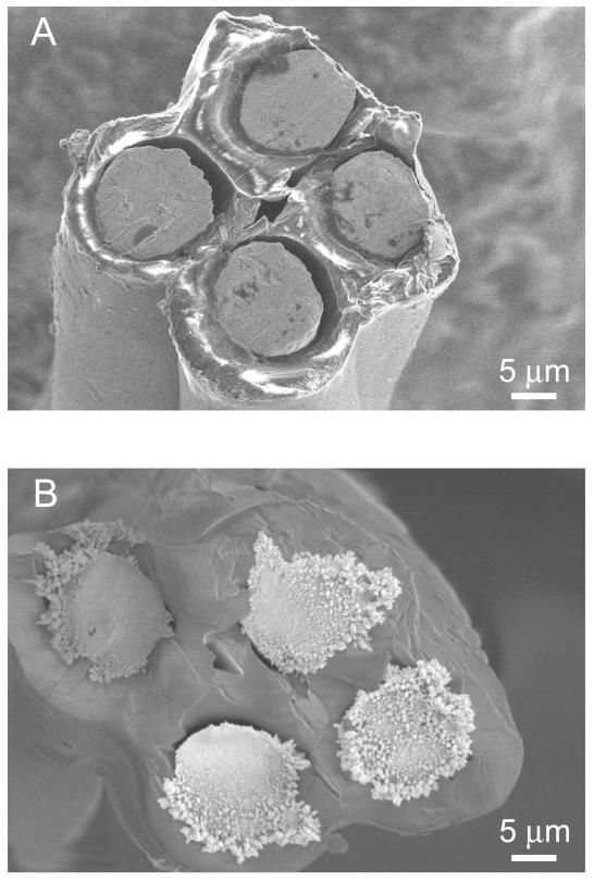
Before electroplating, tetrode tips resembled four flat, slate-like circles surrounded by insulation (Fig. 1A) and had electrode impedances of 2MΩ to 3 MΩ. Tetrodes that were electroplated to 250 kΩ using standard parameters (2 μA current pulses and an unmodified gold-plating solution) had an uneven, granular coating of gold crystallites with larger crystallites near the outside edges (Fig. 1B). All attempts to lower the impedance of the four electrodes in a tetrode to below 100 kΩ using standard electroplating parameters resulted in shorting. Varying the electroplating current and concentration of gold-plating solution using DI (no other additives) also resulted in shorting.
Fig. 1.
Scanning electron microscope images of a tetrode (A) before electroplating and (B) after electroplating to 250 kΩ using an unmodified gold-plating solution.
Creating a “rice-like” texture
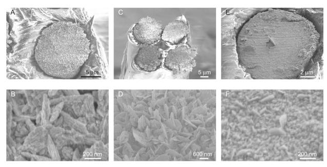
One set of electroplating parameters, 2 μA current pulses and the 90% multi-walled carbon nanotube (MWCNT) solution, was able to consistently produce 250 kΩ tetrodes with the same “rice-like” texture as described by Keefer et al. [13] (Fig. 2A). Closer examination revealed the texture contained bladed crystallites (Fig. 2B). The 90% polyethylene glycol (PEG) solution produced a similar bladed texture (Fig. 2D), but the crystallites had uneven growth across the electrodes and appeared less “rice-like” (Fig. 2C). Coatings made with the 90% deionized water (DI) solution were much flatter (Fig. 2E) and had a small amount of bladed crystallite growth (Fig. 2F). All attempts to lower tetrodes impedances to below 100 kΩ after adding 90% MWCNT, 90% PEG, or 90% DI to the gold-plating solution resulted in shorting.
Fig. 2.
(A) Tetrodes with “rice-like” coating and impedances of about 250 kΩ were made by electroplating with a 90% MWCNT solution and 2 μA current pulses. (B) A high-magnification image shows that the “rice-like” coating was made up of bladed crystallites. (C) Tetrodes with a similar coating and an impedance of about 250 kΩ were made by electroplating with 90% PEG solution and 2 μA current pulses. (D) The texture of this coating was also made up of bladed crystallites. (E) A much flatter, 250-kΩ coating was made by electroplating with a 90% DI solution and 2 μA current pulses. (F) This coating texture contained only a few bladed crystallites.
Electroplating to below 100 kΩ
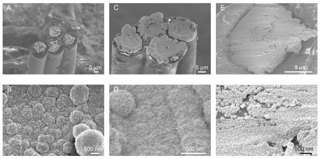
Only two of the forty sets of electroplating parameters tested were able to consistently produce tetrodes with impedances below 100 kΩ without shorting: the 75% PEG and the 75% MWCNT solutions, both using 0.1 μA current pulses. The coatings made with the 75% MWCNT solution had a globular appearance (Fig. 3A) and a rough, large surface area texture (Fig. 3B). The coatings from the 75% PEG solution were also globular and rough at high magnification but grew large around the perimeter of the electrodes (Figs. 3C and 3D). Tetrodes with impedances as low as 30 kΩ were produced using these two sets of electroplating parameters.
Fig. 3.
(A) Tetrodes with globular coatings and impedances of 40-70 kΩ were made by electroplating with a 75% MWCNT solution and 0.1 μA current pulses. (B) The resulting coating texture was very rough. (C) Globular coatings with more peripheral growth but also with impedances of 40-70 kΩ were made by electroplating with a 75% PEG solution and 0.1 μA current pulses. (D) The texture was also rough but had fewer globules than the coating made with the MWCNT solution. (E) A very different coating was made by electroplating with a 75% DI solution and 0.1 μA current pulses. Because these parameters caused tetrodes to short when plated below 100 kΩ, the coating shown was only plated to 250 kΩ. (F) This coating was only sparsely covered by crystallites.
Without additives (using a 75% DI solution and 0.1 μA current pulses), tetrodes plated to below 100 kΩ were shorted. Figs. 3E and 3F shows a tetrode plated to 250 kΩ using the 75% DI solution.
Electrical properties of the coatings
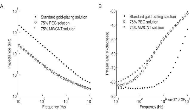
Electrical impedance spectroscopy was performed on two tetrodes that were electroplated to below 100 kΩ (using 75% MWCNT and 75% PEG solutions). Their impedance spectra were similar across frequencies (Fig. 4A). At 1 kHz, the two tetrodes had impedances of 70 kΩ and phase angles of about −50 °. These tetrodes were less capacitive than a standard gold-plated, 250-kΩ tetrode which had a −80 ° phase angle at 1 kHz (Fig. 4B).
Fig. 4.
Electrical impedance spectroscopy of the tetrodes electroplated to 70 kΩ (using 75% MWCNT and 75% PEG solutions) compared with tetrodes plated to 250 kΩ (using unmodified gold-plating solution). (A) The impedances of the tetrodes made with the 75% MWCNT and PEG solutions were almost identical and were lower than the impedances of the tetrodes made with the unmodified gold-plating solution, across all frequencies. (B) The low-impedance tetrodes were much less capacitive than the tetrodes plated with unmodified gold-plating solution, as measured by phase angles.
Saline test
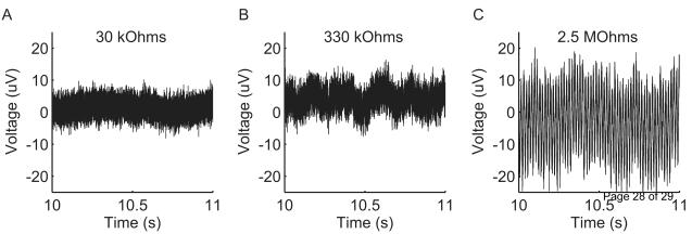
A tetrode recording in a saline bath revealed that a low-impedance electrode had a smaller noise level than a standard-impedance electrode and an unplated electrode. Fig. 5 shows a representative one-second recording of three electrodes with different impedances on the same tetrode. The low-impedance electrode (30 kΩ) had an RMS noise level of 2.2 μV, the standard-impedance electrode (330 kΩ) of 3.0 μV, and the unplated electrode (2.5 MΩ) of 9.0 μV with a large 60-Hz noise component.
Fig. 5.
Simultaneous recordings in saline of three electrodes with different impedances on the same tetrode. The low-impedance electrode (30 kΩ) had an RMS noise level of 2.2 μV, the standard-impedance electrode (330 kΩ) of 3.0 μV, and the unplated electrode (2.5 MΩ) of 9.0 μV with a large 60-Hz noise component. The one-second sample shown was similar to the rest of the recording.
The noise levels of the saline recordings were similar to estimates of the expected thermal noise. Because the electrodes had a frequency-dependent complex impedance, RMS thermal noise was estimated as:
where k is Boltzmann’s constant, T is temperature, R is the real component of the complex impedance at a given frequency, and Δf is the frequency difference between impedance measurements. Using 40 impedance values measured at frequencies between 1 Hz and 10 kHz, the thermal noise of the low-impedance electrode (30 kΩ) was estimated to be 1.5 μV, a standard-impedance electrode (330 kΩ) was 3.3 μV, and an unplated electrode (2.5 MΩ) was 8.3 μV.
In vivo test
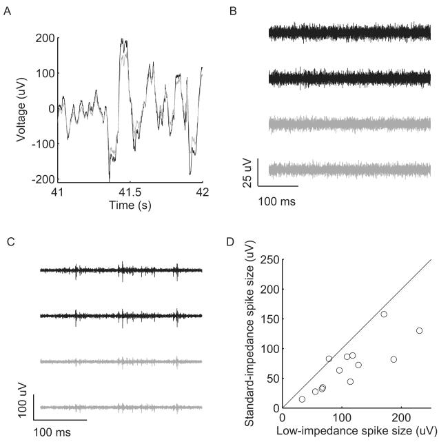
Tetrode recordings in anesthetized rats were sensitive to the impedance of the electrodes. Four tetrodes were used to record signals in 13 distinct locations with spiking activity in two anesthetized rats. Three tetrodes had impedances of 50 kΩ, 50 kΩ, 250 kΩ, and 250 kΩ. The fourth tetrode had impedances of 50 kΩ, 270 kΩ, 2.5 MΩ, and 2.5 MΩ. When the signals were filtered from 1 Hz to 475 Hz in MATLAB to look at local field potentials, the low-impedance electrodes (50 kΩ) consistently recorded approximately 20% larger signals than standard-impedance electrodes (250 kΩ) with no noticeable difference in frequency content (Fig. 6A).
Fig. 6.
In vivo recordings using tetrodes that contain both low-impedance (~50 kΩ) and standard-impedance (~250 kΩ) electrodes. (A) Low-impedance electrodes recorded approximately 20% larger local field potentials (filtered from 1 Hz to 475 Hz) than standard-impedance electrodes. The one-second sample shown was from the middle of the recording and was representative of the rest of the recording. (B) A background recording (filtered from 600 Hz to 6 kHz) without large spikes. The black traces were from the low-impedance electrodes on the tetrode, and the gray traces were from the standard-impedance electrodes. The RMS background level was 2.7 μV for low-impedance electrodes and 2.5 μV for standard-impedance electrodes. (C) A tetrode recording with spikes shows that the amplitudes of the spikes were larger on the low-impedance electrodes than the standard-impedance electrodes. (D) In twelve of the thirteen recording locations, the largest spike seen on any electrode had larger mean peak-to-peak amplitudes on the low-impedance electrodes than on the standard-impedance electrodes.
When the signals were filtered from 600 Hz to 6 kHz to observe spiking activity, the RMS background noise levels between spiking events were slightly larger in the low-impedance electrodes (2.7 μV) than standard-impedance electrodes (2.5 μV) (Fig. 6B). The reduction in thermal noise seen in the saline tests was obscured by other forms of noise, such as small action potentials from distant neurons.
Additionally, the peak-to-peak amplitude of spikes was generally larger on low-impedance electrodes than on standard-impedance tetrodes within a tetrode. Fig. 6C shows one example. For the largest spike seen on any electrode at each of the thirteen recording locations, the mean amplitude of the spike on the low-impedance electrodes was compared to the mean amplitude of the same spike on the standard-impedance electrodes. In twelve of the thirteen locations, the amplitudes of the spikes were larger on the low-impedance electrodes than the standard-impedance electrodes (Fig. 6D). One very large spike recorded at one of the locations was excluded from this graph because it only occurred twice during the two-minute recording, and the second largest spike was used instead. However, the excluded spike also had a larger-amplitude spike on the low-impedance electrodes. The presence of larger-amplitude spikes on the low-impedance electrodes was not dependent on whether low-impedance or standard-impedance spikes were used to listen for spiking activity while turning the tetrodes.
Discussion
Electroplating is a simple yet powerful technique that is not used to its full potential by most neurophysiologists who electroplate their own microelectrodes. Commercial plating solutions designed for industrial applications are often used straight out of the bottle to electroplate tetrodes. However, by mixing additives with the electroplating solution and varying other electroplating parameters, neurophysiologists can easily create a variety of coatings with different crystallite shapes, sizes, and densities.
We used electroplating additives to produce several distinct tetrode coatings, most notably globular coatings with a very large surface area and coatings with the “rice-like” texture described by Keefer et al. [13]. Tetrodes with the globular coatings could reach impedances of 30 kΩ to 70 kΩ without shorts and had a less negative phase angle than standard 250 kΩ tetrodes. Coatings with a bladed texture could be produced using either multi-walled carbon nanotubes (MWCNT) or polyethylene glycol (PEG) solutions, implying that the coating was not created by the deposition of non-dispersed bundles of carbon nanotubes as suggested by Keefer et al. [13]. Rather, we believe the MWCNT and PEG additives acted as electroplating inhibitors, which adsorbed to electrode surfaces and changed the dynamics of electrocrystallization to favor the deposition of new crystallites over continued growth of existing crystallites [14, 15, 16]. PEG is a known electroplating inhibitor [17], and the coatings produced with MWCNTs and PEG were similar but not identical because the molecules are different sizes and likely have different strengths of inhibition. Coatings made with inhibitors have other benefits, such as increased adhesion to the substrate [18]. Merrill and Ainsworth [19] found that adding gelatin to a platinum plating solution increased the adhesion of the platinum coating to tungsten microelectrodes. A downside of using electroplating inhibitors is that electroplating a single tetrode to below 70 kΩ can take up to 20 minutes, as opposed to the 1 to 2 minutes needed to electroplate a single tetrode to 250 kΩ without inhibitors.
We found that the low-impedance tetrode coatings reduced the thermal noise measured in a saline test, but this noise reduction was weaker in an in vivo recording. However, in the in vivo recordings in anesthetized rats, the low-impedance electrode coatings minimized signal loss through shunt pathways and resulted in a larger signal for local field potential and for spikes. Longer-term implantation creates a more complex situation because of tissue reaction and electrode encapsulation. There is conflicting evidence about whether microelectrodes with very low impedances improve the quality of chronic in vivo neural recordings. Some studies have found that low-impedance microelectrodes improved recordings while others did not find a significant difference. One study found that low-impedance coated microelectrodes recorded 17% more quality units and also reduced low-frequency artifacts over six weeks post-implantation [8]. Another long-term study was able to record neural activity with a high signal-to-noise ratio (SNR) using microelectrodes with impedances ranging from 50 kΩ to 1 MΩ and suggested that low impedances were not necessary for high-SNR recordings [20]. This study also found that SNR and impedance were significantly correlated for one animal but not for another animal, while signal quality and impedance were significantly correlated for both animals. We were unable to find any published study that indicated that lower-impedance microelectrodes provide lesser quality recordings.
Neurophysiologists interested in testing whether low-impedance tetrodes work for their specific research application can conveniently do so by using electroplating additives. However, low-impedance tetrodes take longer to prepare and may not work for all applications. We found that MWCNT solutions created more compact coatings than PEG when viewed in a scanning electron microscope, but PEG is more commonly found in neurophysiology labs and was equivalently effective at lowering impedances. Electroplating is simple to perform yet has great flexibility and can be modified to create coatings with a wide variety of properties. In addition to the electroplating parameters varied in this study (additives, plating current, and plating solution concentration), many other variables can influence the electroplating process (e.g., pH, stirring, pulse timing, and temperature). Electroplated microelectrode coatings can be made to have a range of properties, and their usefulness for neural recording applications is only starting to be explored.
Acknowledgements
This work was supported by a grant from the University of Minnesota Institute for Engineering in Medicine (IEM) and an NIH T32-EB008389 training grant. Parts of this work were carried out in the Minnesota Characterization Facility, which receives partial support from NSF through the NNIN program.
Footnotes
Publisher's Disclaimer: This is a PDF file of an unedited manuscript that has been accepted for publication. As a service to our customers we are providing this early version of the manuscript. The manuscript will undergo copyediting, typesetting, and review of the resulting proof before it is published in its final citable form. Please note that during the production process errors may be discovered which could affect the content, and all legal disclaimers that apply to the journal pertain.
References
- [1].McNaughton BL, O’Keefe J, Barnes CA. The stereotrode: a new technique for simultaneous isolation of several single units in the central nervous system from multiple unit records. J Neurosci Meth. 1983;8(4):391–397. doi: 10.1016/0165-0270(83)90097-3. [DOI] [PubMed] [Google Scholar]
- [2].O’Keefe J, Recce ML. Phase relationship between hippocampal place units and the eeg theta rhythm. Hippocampus. 1993;3(3):317–330. doi: 10.1002/hipo.450030307. [DOI] [PubMed] [Google Scholar]
- [3].Wilson MA, McNaughton BL. Dynamics of the hippocampal ensemble code for space. Science. 1993;261(5124):1055–1058. doi: 10.1126/science.8351520. [DOI] [PubMed] [Google Scholar]
- [4].Gray CM, Maldonado PE, Wilson M, McNaughton B. Tetrodes markedly improve the reliability and yield of multiple single-unit isolation from multi-unit recordings in cat striate cortex. J Neurosci Meth. 1995;63(1-2):43–54. doi: 10.1016/0165-0270(95)00085-2. [DOI] [PubMed] [Google Scholar]
- [5].Robinson D. The electrical properties of metal microelectrodes. Proc IEEE. 1968;56(6):1065–1071. [Google Scholar]
- [6].Geddes L. Electrodes and the Measurement of Bioelectric Events. John Wiley & Sons; 1972. [Google Scholar]
- [7].Loeb GE, Peck RA, Martyniuk J. Toward the ultimate metal microelectrode. J Neurosci Meth. 1995;63(1-2):175–183. doi: 10.1016/0165-0270(95)00107-7. [DOI] [PubMed] [Google Scholar]
- [8].Ludwig KA, Uram JD, Yang J, Martin DC, Kipke DR. Chronic neural recordings using silicon microelectrode arrays electrochemically deposited with a poly(3,4-ethylenedioxythiophene) (pedot) film. J Neural Eng. 2006;3(1):59–70. doi: 10.1088/1741-2560/3/1/007. [DOI] [PubMed] [Google Scholar]
- [9].Janders M, Egert U, Stelzle M, Nisch W. Novel thin film titanium nitride micro-electrodes with excellent charge transfer capability for cell stimulation and sensing applications. Proc 18th Annual International Conference of the IEEE Bridging Disciplines for Biomedicine Engineering in Medicine and Biology Society.1996. pp. 245–247. [Google Scholar]
- [10].Cogan SF. Neural stimulation and recording electrodes. Annu Rev Biomed Eng. 2008;10:275–309. doi: 10.1146/annurev.bioeng.10.061807.160518. [DOI] [PubMed] [Google Scholar]
- [11].Paik S, Park Y, Cho D. Roughened polysilicon for low impedance microelectrodes in neural probes. J Micromech Microeng. 2003;13:373–379. [Google Scholar]
- [12].Cui X, Martin D. Fuzzy gold electrodes for lowering impedance and improving adhesion with electrodeposited conducting polymer films. Sensor Actuator Phys. 2003;103(3):384–394. [Google Scholar]
- [13].Keefer EW, Botterman BR, Romero MI, Rossi AF, Gross GW. Carbon nanotube coating improves neuronal recordings. Nat Nanotechnol. 2008;3(7):434–439. doi: 10.1038/nnano.2008.174. [DOI] [PubMed] [Google Scholar]
- [14].Feltham A, Spiro M. Platinized platinum electrodes. Chem Rev. 1971;71(2):177–193. [Google Scholar]
- [15].Lin K, Weil R, Desai K. Effects of current density, pulse plating, and additives on the initial stage of gold deposition. J Electrochem Soc. 1986;133:690–692. [Google Scholar]
- [16].Winand R. Electrodeposition of metals and alloys-new results and perspectives. Electrochim Acta. 1994;39:1091–1091. [Google Scholar]
- [17].Stoychev D, Tsvetanov C. Behaviour of poly (ethylene glycol) during electrodeposition of bright copper coatings in sulfuric acid electrolytes. J Appl Electrochem. 1996;26(7):741–749. [Google Scholar]
- [18].Weil R. The structures of electrodeposits and the properties that depend on them. Annu Rev Mater Sci. 1989;19(1):165–182. [Google Scholar]
- [19].Merrill EG, Ainsworth A. Glass-coated platinum-plated tungsten microelectrodes. Med Biol Eng. 1972;10(5):662–672. doi: 10.1007/BF02476084. [DOI] [PubMed] [Google Scholar]
- [20].Suner S, Fellows M, Vargas-Irwin C, Nakata G, Donoghue J. Reliability of signals from a chronically implanted, silicon-based electrode array in non-human primate primary motor cortex. IEEE Trans Neural Syst Rehabil Eng. 2005;13(4):524–541. doi: 10.1109/TNSRE.2005.857687. [DOI] [PubMed] [Google Scholar]


