Abstract
During needle-based procedures, transitions between tissue layers often involve puncture events that produce substantial deformation and tend to drive the needle off course. In this paper, we analyze the mechanics of these rupture events corresponding to unstable crack propagation during the insertion of a sharp needle in an inhomogeneous tissue. The force-deflection curve of the needle prior to a rupture event is modeled by a nonlinear viscoelastic Kelvin model and a stress analysis is used to predict the relationship between rupture force and needle velocity. The model predicts that the force-deflection response of the needle is steeper and the tissue absorbs less energy when the needle moves faster. The force of rupture also decreases for faster insertion under certain conditions. The observed properties are sufficient to show that maximizing needle velocity minimizes tissue deformation and damage, and consequently, results in less needle insertion position error. The model predicts that tissue deformation and absorbed energy asymptotically approach lower bounds as velocity increases. Experiments with porcine cardiac tissue confirm the analytical predictions.
I. Introduction
Medical needle interventions are a common technique for accessing tissue structures that would be otherwise difficult or impossible to reach. In these procedures, needles are used, for example, to place radioactive seeds at tumor sites, to extract biopsy samples, to inject drugs and to insert catheters during prenatal interventions.
Robotic needle steering has became an active research area in recent years [1], [2], [3], [4], [5]. The robot is used to control the position and orientation of the base of a stiff symmetric needle, or a flexible bevel-tip needle to guide the tip of the needle to a desired target inside the tissue. A desired trajectory for the needle tip is often planned such that the needle tip does not penetrate sensitive tissue or collide with bone. As the needle penetrates tissue, both needle and tissue deform thus altering both the path of the needle and the location of the target. Model-based path planning and online imaged-guided control are used to guide the needle tip along a trajectory that converges to the desired target.
Contrary to what is experienced in homogeneous tissue phantoms, needle insertion into biological tissues often leads to sudden tissue rupture or unstable crack extensions due to tissue inhomogeneity and changes in structure that affect the flow of energy into the tissue cracks [6], [7], [8]. A rupture event occurs when excessive tissue deformation is followed by the sudden propagation of a crack or cracks inside the tissue. During rupture, the stored strain energy is suddenly released to the cracks (or micro cracks) inside the tissue and extends them. This can result in a significant detour from the desired trajectory during needle steering owing both to the initial tissue deformation prior to a rupture event as well as to the uncontrollable propagation of cracks during the rupture.
Such path errors create the need for larger path corrections and, if large enough, may necessitate backing up the needle. Furthermore, they can cause dangerous penetration of sensitive tissue regions. For example, during fetal cardiac interventions, needle insertion into the left ventricle can cause collapse of the chamber such that the subsequent rupture penetrates the rear wall of the ventricle [9].
It is commonly known that faster motions of a sharp tool or needle cause less tissue deformation during cutting or penetrating of a biological material. Less deformation should be partly due to the viscoelastic properties of the material. For example, it was studied in [10] that ultrasonic surgical cutting instruments can cut tissue without any significant tissue deformation partly due to the high frequency periodic velocity of the instrument tip. It was also shown that tissue with higher water content can be more easily cut by an ultrasonic cutter. It is likely that robotic needle insertions, currently modeled as quasistatic processes, can also benefit by controlling velocity to produce less deformation and tissue damage.
Prior work by our group [9] showed that faster needle insertion reduces rupture forces during needle insertions in porcine cardiac tissue. This reduction was attributed to a negative velocity dependence of the fracture toughness of the epicardial layer. In contrast, in this paper, we show that the faster needle insertion reduces tissue deformation prior to a rupture event and also reduces the energy absorbed by the tissue due to the viscoelastic properties of the tissue. We explain that the negative dependency of rupture force on the insertion velocity is due to the geometrical changes at the tip of cracks close to the needle tip and is mostly affected by deformation of the tissue.
The paper is arranged as follows. The next section presents deformation and rupture force models based on the observed force-displacement characteristics of tissue. The following section describes our experiments and the model parameters obtained. The final section presents conclusions.
II. Dynamic Modeling of Needle Insertion
In this section, we describe the force-deflection response associated with needle insertion in a porcine heart as well as the characteristics of the rupture event occuring at the beginning of the needle insertion. Then, we model a such biological organ as a viscoelastic body with a nonlinear Kelvin model and obtain the force-deflection-velocity relation for inserting a needle into the body. We then present a stress analysis that explains the relation between the rupture force and the needle velocity.
A. Force-Displacement Characteristics
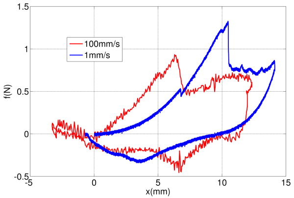
Figure 1 shows force-displacement responses of inserting a sharp rigid needle into a pig heart with the insertion rates of 1 mm/s and 100 mm/s. Details of these tests are presented in section III. The process of each needle insertion can be divided into several events [8]:
Fig. 1.
Force-displacement responses of needle insertions into a pig heart at two rates: 1 mm/s and 100 mm/s.
A deformation event that starts at 0 mm and continues until a deflection at which the needle force reaches its maximum,
A rupture event when an unstable crack suddenly propagates into the tissue right after the force reaches its maximum,
A cutting event that starts after rupture such that the crack propagates in the body in a controlled fashion in response to needle displacement,
A second deformation event that starts when the needle is stopped and continues as the needle is removed.
Comparing the force-deflection curves of two insertions during the first deformation event shows that the displacement and the force of the rupture for 100mm/s insertion are smaller than the displacement and force for 1mm/s insertion.
B. Deformation Model
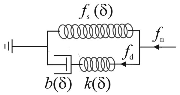
We consider a biological organ as a viscoelastic body and use a modified nonlinear Kelvin model to calculate the force of inserting a needle into the organ [11]. The standard Kelvin model is a linear spring-damper model used to predict the deformation of biological materials under uniform tension. The modified nonlinear Kelvin model has the same architecture as the standard Kelvin model but its components are functions of needle sharpness and tissue deflection, δ (Figure 2). We use deflection-dependent parameters for the modified Kelvin model to include
Fig. 2.
A modified Kelvin model for the needle interacting with a viscoelastic body.
the effect of contact area size, that generally increases with the deflection, on needle force [12] and
nonlinear stress-strain of the material during large displacement of tissue prior to fracture [6].
The parameters of the model are obtained by measurement using the same needle.
A nonlinear force-deflection function fs(δ) defines the force response of the spring of the modified Kelvin model that calculates the static component of the needle force. The series connection of a nonlinear spring k(δ) and a nonlinear damper b(δ) calculates the dynamic component of the needle force. Here, we assume that k(δ) and b(δ) depend on the same function of δ with different ratios. This way, the relaxation time of the model, τs, becomes independent of δ.
| (1) |
This relaxation time is almost independent of the needle shape and can be replaced by the strain relaxation time of the tissue. From the modified Kelvin model (Figure 2), the contact force is given by
| (2) |
where fn is the needle force and fd(δ, t) is the force of the dynamic part of the model defined as a function of time t and deflection δ.
The dynamic force fd is calculated from the system of equations of the dynamic part of the model
| (3) |
| (4) |
| (5) |
where δk is the displacement of the spring and δb is the displacement of the damper.
We first obtain the deflection of the spring from the system of equations. Combining (3), (4), and (1) yields
| (6) |
Taking the time derivative of (5) and combining the result with (6) yields
| (7) |
Here, we see that there is a linear differential equation for spring displacement of the modified Kelvin model instead of a linear differential equation for spring force as is obtained with the standard Kelvin model.
The general solution for (7) is obtained by a convolution integral as
| (8) |
The dynamic force fd is then obtained as
| (9) |
For an insertion with a constant velocity v, (9) yields
| (10) |
Substituting (10) into (2) gives the force-deflection response of the model for insertion velocity v and relaxation constant τs
| (11) |
This force-deflection response (11) shows that increasing the insertion rate always increases the needle force for a given deflection.
At high velocities , the dynamic part of needle force can be approximated using a Taylor series
| (12) |
For v → ∞, the dynamic part of the force-deflection response converges to
| (13) |
This shows that the force-deflection slope of the needle converges to a finite stiffness at an infinite velocity.
Here, we define the velocity v90, as the velocity at which the dynamic force reaches ninety percent of its ultimate value for a given deflection.
| (14) |
As an example, if the relaxation time of a tissue is 1 sec and the considered deflection is 10 mm, then the ninety percent velocity is 50 mm/s.
C. Rupture Force
The balance of energy for a quasi-static crack extension is written as [6]
| (15) |
where dx is the infinitesimal tool displacement, du is the change of deformation energy during the crack extension, Jc is the fracture toughness of the material and dA is the infinitesimal crack area.
If the elastic energy concentrated around the tip of the needle is very small or does not change over the length of the crack during insertion, the change of elastic energy in the body during fracture will be zero du = 0, and consequently the needle force can be obtained by [8]
| (16) |
where wc is the width of the crack. The obtained force is only for a sharp cutting event where a crack grows in a stable fashion and follows the needle tip displacement. In fracture mechanics, the sharp cutting force of a sharp tool is used to evaluate the toughness of materials [6].
The force of a rupture event always goes beyond the sharp cutting force. A crack may not propagate at the sharp cutting force due to the lack of enough stress and energy concentration at the tip of the needle [8]. In this condition, the needle continues to deform the body and to store strain energy inside the body. If a crack extension eventually occurs, it will generally occur in a short period of time such that the tool displacement and the tool work are negligible. A rupture event is due to an unstable crack propagation. An unstable crack propagation occurs due to one or both of the following conditions [6]:
Material change: for example, when the tool passes through a body and reaches a new layer of material with a toughness smaller than the first layer.
Geometrical changes around a crack tip: for example, when a blunt crack becomes sharp and remains sharp during rupture.
The rupture force should not be estimated by the force of sharp cutting (16). A rupture starts when the concentrated strain energy around the crack will be enough to extend a crack inside the body. Prediction of the rupture force requires calculations of the stress at a microscopic level around the tip of the needle and in the small cracks around the needle tip.
Here, we use a stress analysis to evaluate the force of rupture for needle insertion. Assume the pressure over the contact area between the needle and tissue is constant, then we can write:
| (17) |
where p is the pressure and Ac is the size of the contact area. The stress at a blunt crack tip is intensified by a concentration factor Ks that depends on the crack tip curvature [6]. A rupture event starts when the stress and strain energy is sufficient around the tip of a crack. We conclude that the force of rupture should be inversely proportional to the crack stress concentration factor Ks and proportional to the size of the contact area:
| (18) |
Increasing the rate of needle insertion can reduce the contact area and make the crack sharper depending on the material type and the shape of the needle. It was reported for a variety of materials including soft viscoelastic material such as rubber and soft polymer that increasing the rate of a crack extension reduces the bluntness of the crack and reduces the force required to initiate and propagate a crack [6].
We assume that the rupture force decreases or remains constant when the rate of needle insertion increases. In this way, we can represent the force of rupture as
| (19) |
where fr(·) is a continuous function of velocity. We show that a faster insertion causes smaller tissue deflection and tool work at the beginning of a rupture event. Substituting (19) into (11) relates the rupture deflection to the insertion velocity.
| (20) |
It can be shown that increasing the velocity v decreases the rupture deflection. We also conclude that if fr changes smoothly for velocities higher than v90, then the rupture deflection does not significantly change for insertions faster than v90.
The tool work prior to rupture can be obtained from
| (21) |
It can be shown that increasing the velocity v decreases the tool work. Thus, we can also conclude that if fr changes smoothly for velocities higher than v90, then the tool work does not significantly change for insertions faster than v90.
The tool work is absorbed by the tissue during the rupture or prior to the rupture. The absorbed energy prior to the rupture causes plastic damage to the tissue. The absorbed energy during the rupture extends the cutting crack. A larger unstable crack causes more position error during needle steering since an unstable crack does not necessarily follow the trajectory of the needle.
III. Experimental Results
A series of needle insertion experiments were performed to validate that the force-deflection characteristics of the needle fits a modified Kelvin model and to verify that the force, tool work, and the deflection at the moment of a rupture event follow the analytical predictions of the model.
A. Methods and Materials
A linear actuator instrumented with a Sensotec model 31, 22 N tension/compression load cell and a 1.1 mm diameter tri-pointed surgical needle was used to perform the experiments (Figure 3). The needle is controlled such that its velocity remains constant during insertion. The linear actuator is commanded through a trapezoidal velocity profile moving the needle into the tissue at a specified peak velocity. The linear actuator reached maximum accelerations near 10 m/s2. The output of load cell was filtered using a low pass filter with a cutoff frequency of 100Hz to remove the force sensor noises. Force and position data were collected at a 2 kHz sample rate during needle insertion.
Fig. 3.
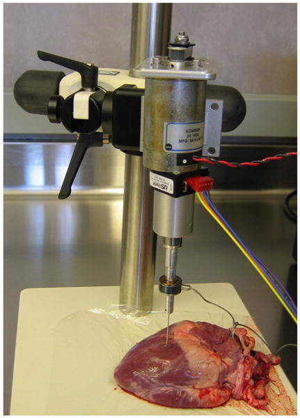
Needle insertion setup.
Needle insertion tests were performed for a range of velocities within an area of about 2cm × 2cm on the heart wall. The selected area is almost flat and visually appears homogeneous. Fresh pig hearts were obtained from a grocery store, refrigerated for less than one hour and the tests were performed over a period of less than two hours. The pig heart tissue is composed of three layers. A thin outer epicardial layer is followed by a thick muscular myocardium that constitutes approximately 95 percent of the heart wall thickness. Insertion tests were performed on the epicardial and myocardial layers.
B. Model Parameters and Output
An initial set of experiments were performed from which we obtained the parameters of the model (11). First, the force fs(δ) was obtained from the nonpenetrating needle force-deflection curve using a velocity of 1 mm/s and a maximum deflection of 6 mm. The resulting force-deflection curve is
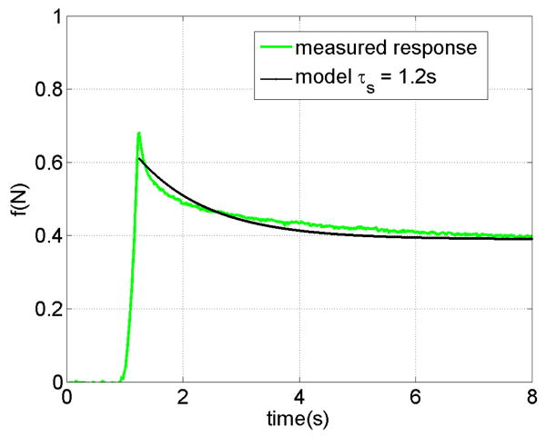
The relaxation time constant of the heart in contact with the needle is obtained from the response of the tissue shown in Figure 4. In this test, the needle penetrates the tissue with the velocity of 20 mm/s for a maximum deflection of 6 mm and then stops. the force fits an exponential response. with time constants τs = 1.2 sec. Based on the measured relaxation time, v90 is 83 mm/s for the deflection of 10 mm.
Fig. 4.
The relaxation response of a pig heart during contact with a needle.
The stiffness of the dynamic model, k(δ), is obtained by penetrating the heart with a velocity of 100 mm/s and comparing the force at this velocity with the force at 1 mm/s velocity for the same deflection. The model predicts the force difference of k(δ)δ based on (13) and we use this to identify k(δ). The resulting stiffness is largely independent of δ in this case and so we take stiffness as a constant, k = 150 N/m.
C. Evaluation of the Deformation model and the Analytical Results
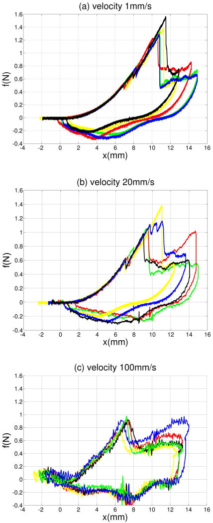
Figures 5a-5c present five overlaid force-displacement trajectories for three needle velocities: 1 mm/s, 20 mm/s, and 100 mm/s. Each force-displacement trajectory includes a deformation mode followed by an unstable crack extension. The results show that needle insertion into an organ wall includes an unstable crack extension and also demonstrate that the force-deflection responses of the needle insertion prior to the unstable crack extension are repeatable. There is variation in the forces of rupture, however.
Fig. 5.
Overlaid force-deflection curves of needle insertions at (a) 1 mm/s (b) 20 mm/s and (c) 100 mm/s.
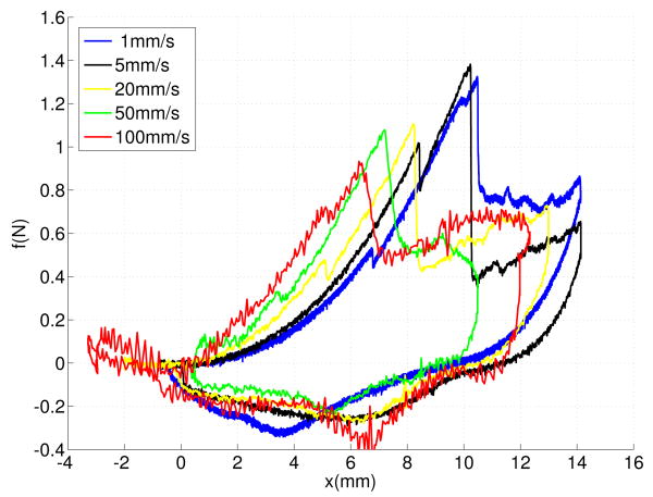
Figures 6 compares force-displacement trajectories for five insertion velocities including 1 mm/s, 5 mm/s, 20 mm/s, 50 mm/s and 100 mm/s. The force-deflection curves of faster insertions are steeper.
Fig. 6.
Force-deflection curves of needle insertions at five different velocites: 1 mm/s, 5 mm/s, 20 mm/s, and 100 mm/s
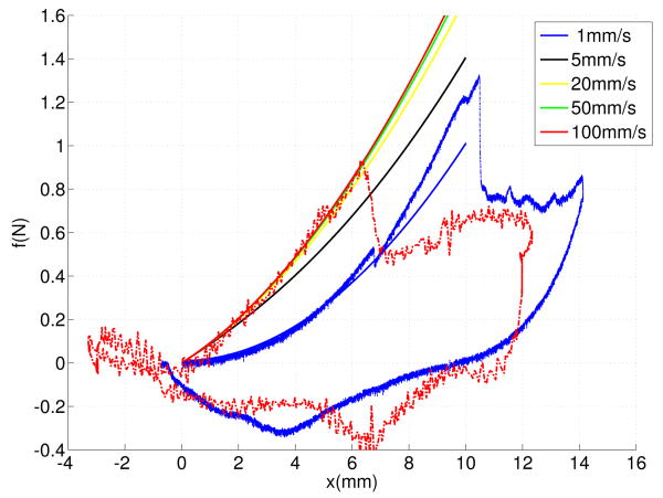
Figures 7 shows the force-deflection curves of the deformation model at five velocities. The force-deflection of higher velocities converge to the force-deflection response of 100m/s faster than the measured force responses. This is due to nonlinear dynamic properties of the tissue, which was not considered by the model.
Fig. 7.
Force-deflection curves of the modified Kelvin model at five different velocties 1 mm/s, 5 mm/s, 20 mm/s, and 100 mm/s.
Table I lists the average force, the average deflection, the average tool work, and the average crack length of insertions at five different velocities at the moment of rupture. The results show a negative dependency of the average deflection, force, tool work, and crack length on the insertion velocity. The results also show that the rupture values for velocities of 50 mm/s and 100 mm/s are approximately the same.
TABLE I. Properties of the needle insertions with five different velocities.
| v | fr (N) | δr (mm) | W (m J) | lc (mm) |
|---|---|---|---|---|
| 1 | 1.37±0.11 | 11.04±0.34 | 7.56 | 10.55 |
| 5 | 1.35±0.107 | 10.98±0.044 | 7.41 | 10.3 |
| 20 | 1.108±0.15 | 10±0.93 | 5.54 | 7.19 |
| 50 | 0.85±0.34 | 7.5±1.41 | 3.18 | 3.29 |
| 100 | 0.88±0.08 | 7.04±0.42 | 3.125 | 3.18 |
IV. Conclusions
Needle insertion into biological materials can produce rupture events and unstable crack propagations. It was shown that the deflection, the force, and the tool energy of a rupture event can decrease as needle velocity increases. We conclude that faster needle insertions can be employed in order to increase position accuracy during needle steering and to decrease tissue damage. The model predicts a finite insertion velocity that closely matches the performance achieved by an infinite velocity, which can be calculated from the relaxation time of the tissue.
Acknowledgments
The authors thank Peter Russo and Matt Heverly for their contributions to the paper.
This work was supported in part by the National Institutes of Health under grant 1R01HL087797.
Contributor Information
Mohsen Mahvash, Email: mahvash@bu.edu.
Pierre E. Dupont, Email: pierre@bu.edu.
References
- 1.DiMaio SP, Salcudean SE. Interactive simulation of needle insertion models. IEEE Transactions Robotics. 2005;52(no. 7):1167–1179. doi: 10.1109/TBME.2005.847548. [DOI] [PubMed] [Google Scholar]
- 2.Webster RJ, Kim JS, Cowan NJ, Chirikjian GS, Okamura AM. Nonholonomic modeling of needle steering. International Journal of Robotics Research. 2006;25(no. 5–6):509–525. [Google Scholar]
- 3.Duindam V, Alterovitz R, Sastry S, Goldberg K. Screw-based motion planning for bevel-tip flexible needles in 3d environments with obstacles. IEEE International Conference on Robotics and Automation; Pasedina, CA. May 2008; pp. 2483–2488. [DOI] [PMC free article] [PubMed] [Google Scholar]
- 4.Kallem V, Cowan N. Image guided control of flexible bevel-tip needles. IEEE International Conference on Robotics and Automation; Roma, Italy. April 2007; pp. 3015–3020. [DOI] [PMC free article] [PubMed] [Google Scholar]
- 5.Sears P, Dupont P. Inverse kinematics of concentric tube steerable needles. IEEE Int. Conference on Robotics and Automation; Rome, Italy. 2007; pp. 1887–1892. [DOI] [PMC free article] [PubMed] [Google Scholar]
- 6.Atkins AG, Mai YW. Elastic and plastic fracture: metals, polymers, ceramics, composites, biological materials. 1st. Chichester: Ellis Halsted Press; 1985. [Google Scholar]
- 7.Lathrop A, Smith R, Webster R. Needle-membrane puncture mechanics. Needle Steering Workshop, MICCAI; 2008. [Google Scholar]
- 8.Mahvash M, Hayward V. Haptic rendering of cutting, a fracture mechanics approach. Haptics-e, the Electronic Journal of Haptics Research. 2001 November;2(no. 3) [Google Scholar]
- 9.Heverly M, Dupont P, Triedman J. Trajectory optimization for dynamic needle insertion. Proceedings of the IEEE International Conference on Robotics; Barcelona, Spain. 2005; pp. 1658–1663. [Google Scholar]
- 10.chan KK, Watmough DJ, Hope DT, Moir K, Chan F. The mode of action of surgical tissue removing devices. IEEE 1985 Ultrasonics Symposium; 1985; pp. 855–59. [Google Scholar]
- 11.Fung YC. Biomechanics, Mechanical Properties of Living Tissues. Springer Verlag; New York: 1981. [Google Scholar]
- 12.Johnson KL. Contact Mechanics. Cambridge University Press; 1987. [Google Scholar]


