Abstract
Mandibulo-maxillary fixation (MMF) screws are inserted into the bony base of both jaws in the process of fracture realignment and immobilisation. The screw heads act as anchor points to fasten wire loops or rubber bands connecting the mandible to the maxilla. Traditional interdental chain-linked wiring or arch bar techniques provide the anchorage by attached cleats, hooks, or eyelets. In comparison to these tooth-borne appliances MMF screws facilitate and shorten the way to achieve intermaxillary fixation considerably. In addition, MMF screws help to reduce the hazards of glove perforation and wire stick injuries. On the downside, MMF screws are attributed with the risk of tooth root damage and a lack of versatility beyond the pure maintenance of occlusion such as stabilizing loose teeth or splinting fragments of the alveolar process. The surgical technique of MMF screws as well as the pros and cons of the clinical application are reviewed. The adequate screw placement to prevent serious tooth root injuries is still an issue to rethink and modify conceptual guidelines.
Keywords: Mandibulo-maxillary fixation, cortical bone screws, MMF screw design, surgical technique, adverse effects, tooth root injuries/types of lesion
BACKGROUND/OBJECTIVES
Intermaxillary (mandibulo-maxillary fixation, MMF) is regarded as the crucial step in the management of maxillofacial trauma since it secures the interrelationship of the occlusal surfaces, which is the absolute essential step in reduction of fragments in both jaws. Temporary intraoperative MMF is distinguished from prolonged MMF maintained for varying time periods postoperatively as a conservative modality for fracture treatment. MMF is employed in orthognathic surgery, and occasionally to induce weight loss in morbid obesity.1,2,3 Historically, a plethora of techniques has been offered to join the mandible with the maxilla.
In essence, a more or less complex, mostly metallic framework was attached to the teeth to provide support and anchor points for fixation of the jaws with interconnecting elastics or wires between the dental arches. In dentate patients, tooth-borne devices such as chain-linked interdental wires, wired arch bars, or cast metal cap splints were used for many decades.
In partially or completely edentulous jaws, individual partial or complete dentures or “gunning” type splints equipped with hooks were either attached to residual teeth or circumferentially wired or directly screwed to the alveolar processes to create an “occlusal platform” prior to the application of mandibulo-maxillary ligatures.4
Direct transosseous wiring to procure a bone-borne hold for perialveolar MMF wires is communicated in the literature5,6,7 but is no longer routinely used. Nowadays, these traditional techniques are challenged by cortical bone screws inserted into the alveolar process of the mandible and maxilla, providing anchor points for MMF linkage with specialized screw heads.
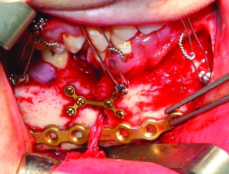
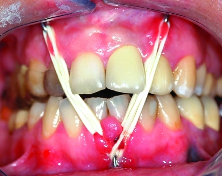
The increasingly popular usage of conventional bone screws with the heads kept at 4 to 5 mm above the mucosa or bone level paved the way for the commercial manufacturing of explicitly designed self-tapping or self-drilling MMF screws during recent years. Among the forerunners of mere single piece MMF screws were screws used in conjunction with stainless steel wire hooks or short, two or three hole, segments of miniplates (“hanger plates”). The coupled hooks or the empty plate holes served as anchors for MMF ligatures (Fig. 1). An example still of interest is the spino-mental fixation, where two screws fitted with hooks are positioned below the anterior nasal spine and shortly above the mental protuberance to establish MMF in a very simple manner.8,9
Figure 1.
“Hanger plates” for mandibulo-maxillary fixation (MMF). Short plate segments fixed transmucously with cortical bone screws are used as fasteners for the intermaxillary wire ligatures. “Hanger plates” were among the forerunners of specialized MMF screws.
In complete edentulism, contiguous interarch plates fixed with cortical bone screws can establish MMF at an adequate vertical bite dimension without the necessity for interposition of dentures.10
This article outlines the surgical technique and a rationale for the use of MMF screws with an appraisal of indications and contraindications as well as inherent problems and typical complications.
SPECIALIZED MMF SCREWS
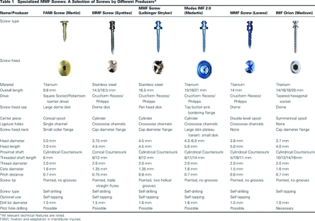
Conventional cortical bone screws were modified to meet the requirements of the MMF-installation procedure (Table 1). In the mandible, the outer cortices of the lateral alveolar process, the retromolar field and the mental protuberance consist of hard cancellous bone up to 6 mm in thickness with a homogenous plane surface. In contrast the alveolar bone in the anterior mandible and the entire buccal maxilla is a thin layer of soft spongy consistency.11 In the latter regions the underlying tooth root morphology is reflected by the alveolar juga.
The torque necessary to drive self-tapping or self-drilling MMF screws into bone is of varying amount and quality, and must be compatible with the material and the technical design of such a screw as well as by the size and dimension of the hand held screwdriver it is coupled to during the insertion. To prevent fractures of the screw shaft or shearing of the screw head under rotational stresses MMF screws are milled out of stainless steel or unalloyed high-grade titanium. Conventional titanium screws already show a tendency to deform as soon as wire ligatures are applied and tightened. The shafts of MMF screws have a pointed tip with a reduced thread diameter. Self-tapping screws are grooved (single, double, or triple straight or helical flutes) at the tip to provide a reservoir for bone debris. Self-cutting or self-drilling screws have a drill-shaped point to penetrate through the bone with more ease. The screw shafts and the threading profiles correspond to the miniscrews of osteosynthesis systems from the different producers.
The basic configuration of the screw heads resembles a capstan or a spool. The design of the screw heads can differ considerably at the top and the shoulder portion lying underneath a drum-shaped center piece. A metal disk with a large diameter (7 to 9 mm) can either cap the screw head or be located at the base just like a saucer, while the opposite ends are made up by a small collarband or an encircling ridge. Some screw head varieties carry equally sized small flanges at the lower and upper central cylinder (dual top). The borders of the screw heads restrain any sliding motion of ligature wires wound around the central part within their limits. Moreover, the shoulder of the screw head serves as a stop during the insertion procedure and should preclude compression of the surrounding mucosal layer in case of a transmucous application. The top of the screw head must be protective toward the overlying buccal soft tissues and provide a smooth contact zone outruling erosions and mechanical ulcers of the mucosa during longterm installation.
In current samples the central part of the screw head is perforated with one or two channels, i.e., two or four holes perpendicular to its vertical axis with a diameter appropriate for passing a ligature wire (up to gauge 22 or 0.64 mm diameter). The openings of such ligature holes are conically countersunk to facilitate threading in the wires. Ligature wires going through the channels will not slip over the screw head and become dislodged during the fixation period. More importantly the wires are elevated over the mucosal plane and thereby restrained to ride on the incisal edges causing pressure and potential tooth damage.
Large diameter disks at the shoulder portion of the screw heads, i.e., lower plateaus, are also meant to inhibit interferences of the ligatures with teeth. The plateau serves as a fulcrum and redirects the course of the ligature wires in front of the tooth line.
MMF screws employ different drive designs, each requiring a special screwdriver blade. Most common are cruciform drives. In case ligature holes are present below the top, the cruciate slots run parallel to the channels to mark the hole orientation for improved access. Tapered square socket drives allow for self retention on the screw driver, permit an increased torque transfer during insertion and are resistant to cam out. Screws with other drive systems are coupled to the screwdriver blades with holding or grasping sleeves. Power tools are unsuitable for the insertion of MMF screws because a torque limiter would be required to prevent the screw threads from stripping.
SCREW SITE SELECTION
The anatomical site for the placement of MMF screws is chosen with respect to a given fracture location, the dentition, the extent of surgical exposure, the availability and the quality of bone in the direct proximity of the fracture line. The anterior vestibular regions as well as the anterolateral transitional zones (canine and premolar regions) of both jaws are oftentimes considered ideal, because these areas are conveniently accessible and supply an appropriate bone stock clear of tooth roots.
As a matter of principle, the intrabony structures at potential risk for lesions through a screw insertion are reexamined based on the radiographic findings at the onset of the procedure. Panoramic x-rays, axial CT scans, or volume rendered DVTs (digital volume tomography scans/cone beam) are a guideline in bypassing the tooth roots, the maxillary antrum, the mandibular canal, or the mental foramen with preciseness.
In the anterior maxilla the piriform rim below the nasal spine and above the dental apices appears safe for setting MMF screws. A well fitting counterpart in the mandible just as secure is the symphyseal and parasymphyseal area underneath the apices of the incisors and canines. Posteriorly the zygomatico-maxillary crest and the solid oblique line buttressing the outer mandibular cortex offer structural support for MMF screws.
The bone plates at midlevel height along the mandibular body and the lateral surface of the maxillary base are frequently too thin to rule out a screw penetration into the mandibular canal or into an expansively pneumatized maxillary sinus.
Screw placement within the confines of the upper or lower alveolar process is suggested to increase the hazards of harming the tooth roots (Figs. 2 and 3). The width of the interdental bony septa converges towards the alveolar limbus, while the root circumference of the adjacent teeth enlarges. For that reason the risk of hitting a tooth root raises progressively with positioning the screws closer to the coronal third of the roots (Figs. 2 and 4).
Figure 2.
Lower half of the roots of permanent teeth exposed through a bone window in (A) left mandibular quadrant and (B) left maxillary quadrant. Note the width of the interdental bony septae diminishing toward the alveolar limbus and crest.
Figure 3.
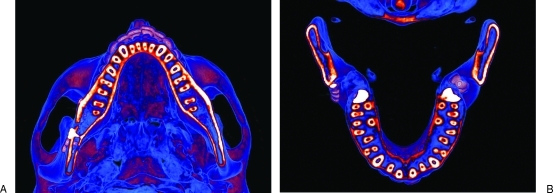
Colored CT scans highlighting the (A) mandibular and (B) maxillary tooth roots in axial planes. Note the tripoid configuration of the maxillary molar roots with the palatal roots at the medial outlet of the lingual roots.
Figure 4.
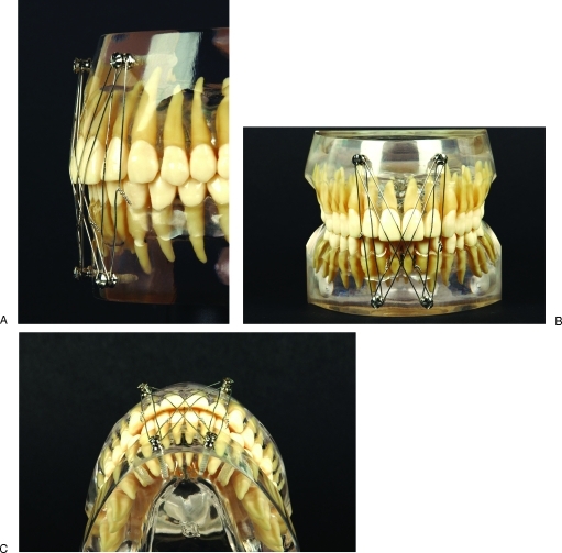
Recommended MMF screw position in the anterior division of the mandible and maxilla. Transparent resin model in three views—(A) sagittal, (B) frontal, and (C) inferior—to clarify the MMF screw position superior and medial to the upper canine root tips as well as inferior and medial to the lower canine root tips. Note the combination of a “Box”- and “X”-wire cerclage pattern.
Additional risk factors for damage are the dense approximation of the dental roots in the lower front and in the dorsal portion of the alveolar quadrants, notably between the molars. Furthermore the molar roots can be irregularly oriented in the bucco-lingual direction and have polygonal axial cross sections.
No attempt should be made to drive MMF screws into the interradicular spaces of the mandibular or maxillary molars due to the minute sagittal and vertical bone dimensions. Moreover the palatine roots of the upper molars would obviate the horizontal insertion depth of the screws (Figs. 2B and 3B).
Apart from the bone and tooth root conditions, the intraoral soft tissue coverage must be acknowledged as a second criterium for screw placement. Above all, this becomes important in transmucosal screw applications for long term periods of immobilization.
Usually the height of the entire upper vestibular sulcus reaches to the level of all bony areas eligible for MMF screw insertion. Only a broad and resilient attachment of the upper lip frenulum may present more difficult access to the piriform rim. The height of the inferior labial sulcus, however, is diminished from canine to canine by the paired mentalis and the lower lip depressor muscles arising from the bony surface at the midjugal or midroot level of the lower incisors. This flexible muscular layer must be pierced angulating the MMF screw downward onto the mental protuberance. The inclination of the screw can be maintained to keep the screw head above the mucosa. Alternatively the screw may be directed into a horizontal course, which will bury the screw head into the soft tissue below of the lower anterior vestibulum.
In the mandibular premolar region, the loose soft tissue envelope immediately surrounding the mental foramen must be avoided in the placement of MMF screws in order not to catch, twist or sever the superficially emerging mental nerve branches or the neurovascular bundle. The mucogingival line and the attached gingiva immediately adjacent to it give a reliable guidance to the intermediate third of the tooth roots both in the mandible and the maxilla. The firmly adherent mucosal layer simplifies the insertion of MMF screws in as much as protruding soft tissues will not obscure the drill hole if the contact to the bony surface is lost.
The unprecedented safety technique is surgical exposure of the bony surface in the fracture territory prior to screw placement. In this fashion the axes and density of the tooth roots as well as the width of interdental spaces can be determined in view of the alveolar jugal ridges. If the MMF screws are to be used after the surgical procedure for long-term treatment the screw placement must anticipate possible soft tissue submergence after wound closure.
CERCLAGE PATTERNS
The cerclage wires between the mandibular and maxillary MMF screws can be applied in different patterns, depending on the number and position of the screws. Temporary MMF is usually achieved with 26 or 24 gauge (≈ diameter 0.4 or 0.5 mm) prestretched stainless steel wires ligated around or through the heads of each screw.
Essentially the wire loops can be put on in a vertical or a diagonal direction, resulting either in a straight line parallel order, in a zig zag arrangement or a combination thereof. Avoid wire loops running over the unprotected edges of the upper incisors or the vestibular facet of the upper cuspids, in particular when longstanding postoperative MMF fixation is employed.
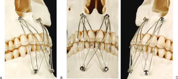
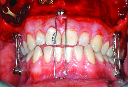
A bilateral block and an additional cross wise (“X”) cerclage pattern based on a total of four MMF screws located on the frontside of the jawbones (Figs. 4 and 5), recommended at the market introduction of specialized MMF systems (Leibinger, Synthes), did not anticipate the problem of orthodontically effective loads on the tooth edges exerted by the pressure of securely tightened wires. Tightening the wires in an anterior cerclage pattern may generate a posterior open bite.12,13 The initial recommendation concentrated on convenient access and advocated safe MMF screw placement to achieve a highly rigid immobilization.
Figure 5.
Interference of “Box”- and “X”-wire cerclages with the edges of the upper incisors in consequence of a “frontside” MMF screw placement. An acrylic splint works as a “stressbreaker” against undesired tooth movement and protects the incisal edges. (A) Right side, (B) front side, and (C) left side.
To overcome the risk of undesirable single tooth movements resulting in loosening or misalignment necessitating later correction an acrylic palatal splint (Fig. 5) can be administered as a stressbreaker. The splint buttresses in the upper teeth and produces a mechanical stability, which neutralizes the retruding forces of the wires. Likewise, the rim of the splinting plate protects the incisal edges against enamel cracking. However this requires dental impressions and laboratory fabrication of an acrylic plate.
The overjet in every Angle class 1 occlusal relationship will lead to ligatures spanning over the upper incisal edges, if the screws are positioned anteriorly. A class II occlusion with mandibular deficiency and a protrusion of the upper incisors aggravates these issues, while an Angle class III occlusion reverses the situation with affect on the lower incisors.
Refinement of the cerclage patterns using a multipoint anchoring with four, six, or eight MMF screws can preclude interference between the pathway of wires and teeth.
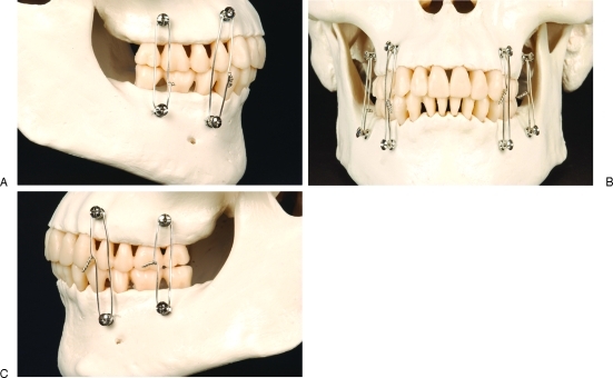
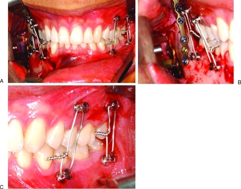
A rather simple way of preventing this problem, however, is to place the MMF screws exclusively on the lateral side of the jaws and use vertical wire loops (Fig. 6). Further, the lateral position of the cerclage wires gives greater control over the posterior occlusion.
Figure 6.
Exclusive placement of MMF screws at the lateral sides of the maxilla and mandible precludes interferences of the pathway of wires and teeth. A set of four MMF screws in the interradicular spaces behind the canines on either side and vertically running wire loops secures a firm centric occlusion. Jaws from: (A) right side, (B) front side, and (C) left side.
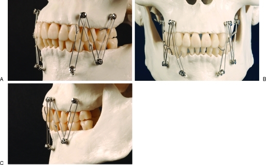
Wires connecting MMF screws on the front and lateral side must avoid the natural curve around the canines. A linear course of the wires in the transition between the lateral and the frontal plane must avoid tooth contact by having the heads of the MMF screws reach far out into the vestibule beyond a tangent line intersecting the canine facet at its peak point (Fig. 7). As a consequence, the lever arm will be elongated, requiring a longer screw shaft to achieve fixation.
Figure 7.
The cerclages will interfere with the facets or edges of the upper canines if the curvature between the lateral side and the ”front side” is crossed. MMF screw heads reaching far out into the vestibulum may avoid this problem at the expense of the length of the lever arm. (A) Oblique right side, (B) front side, and (C) left side.
A typical effect of using wire ligatures along fixation points on the outer surface of the jaws is the tilting of the maxillary and mandibular fragments, often referred to as “bucco-lingual rotation,” which results in occlusal gapping.13 This gapping is confined to the inner facets of the occlusion and can easily go unnoticed clinically because the outer tooth cusps are still in occlusion.
A long distance between fixation points will increase the moment of force exerted by tigthening the wire ligatures in contrast to a shorter space of anchoring. These factors suggest placement of the MMF screws into the interdental/interroot bone spaces to attain direct proximity of the anchors within the opposite dentoalveolar ridges. This reduces tension and lowers the risk for rotational bone displacement and malocclusion. An individualized placement of MMF screws followed by a well-tailored consecutive ligature arrangement is obviously advantageous to any standardized screw position or cerclage protocol, notably with the occurrence of prexisting dental malocclusion or dentofacial deformities.
As a general rule, MMF screws need not be symmetrically juxtaposed from jaw to jaw, but can be aligned in a scattered distribution (Fig. 7), just as long as the overall assembly ensures correct and stable occlusion.
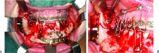
An interesting extension of this technique which is not possible with conventional intermaxillary fixation methods is the temporary insertion of MMF screws into remote non-toothbearing areas such as the zygomatic body, the retromolar trigone or the coronoid notch during surgical exposure. Thereby mobile fragments can be realigned and stabilized through wire traction prior to plate osteosynthesis (Figs. 16 and 17).
Figure 16.
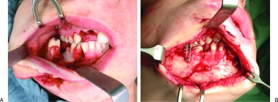
Intraoperative use of MMF screws for four point interarch fixation in open reduction and plating of a double mandibular fracture: parasymphyseal basal wedge left and angle right. (A) The lower incisores including the orthodontic arch in the mandible were lost from trauma. The MMF screws in the mandible were placed after surgical exposure of the fracture sites. Novel use of MMF screw in the anterior border of the ascending ramus yielding an abutment for control of the posterior edentulous fragment during osteosynthesis. (B) Detail showing the ligature placement outside the tooth row maintaining the remote fragment in the reduced position.
Figure 17.
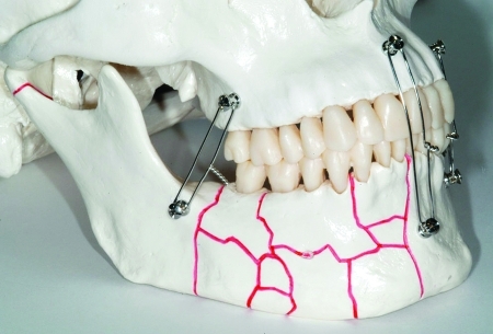
Model of a comminuted fracture extending over the right mandibular body and parasymphysis. Occlusion was secured with MMF screws and wire cerclages. Likewise, in the preceding figure the position of the ascending ramus can be maintained with MMF screws and cerclages anchored outside the dentate alveolar processes.
SURGICAL TECHNIQUE
MMF screws can be inserted under either local or general anesthesia. In essence, a surface local anesthesia, e.g., by application of a pump-spray or gel, will suffice because only the gingiva and the periosteum are responsible for pain transmission. The sensory feedback from deeper intraosseous structures, particularly the periodontal ligaments may be valuable for control of the direction of the screw insertion and a potential need for correction.
Prior to insertion, the oral cavity and the teeth are cleansed with a tooth brush and rinsed with a desinfectant solution (e.g., Octenidinhydrochlorid/ Phenoxyethanol—Octenisept®). Then the surgical site is prepared. After reference to the radiographic images, the bone conditions are further evaluated by palpation to identify the optimal sites for the placement of MMF screws. Soft tissue conditions, the dentition and the pretraumatic occlusal relationships are also considered to choose a cerclage pattern that is compatible with the individual circumstances.
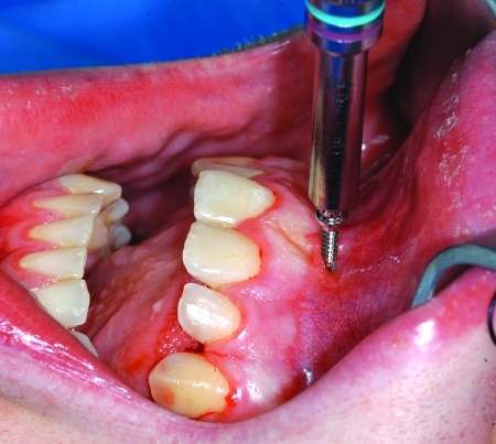
MMF screws can then be inserted in various ways:
Through a perforation of the closed mucosa (Figs. 8 and 9) or after an open approach exposing the bone surface (Figs. 10–16)
Self-tapping after drilling full thickness pilot holes throughout all bony layers or after predrilling just the outer cortex, respectively
Completely self-drilling (Figs. 8–10)
Figure 8.
Transmucous insertion of a self-drilling MMF screw into the interradicular space of the upper central incisors, next to the small-based maxillary labial frenum.
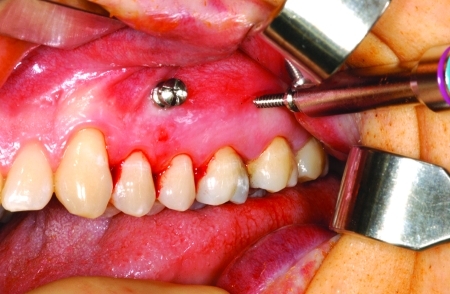
Figure 9.
Self-drilling MMF screws inserted at the level of mucogingival junction into the mesiodistal interradicular spaces between the first and second premolar as well as the first and second molar in the upper left quadrant.
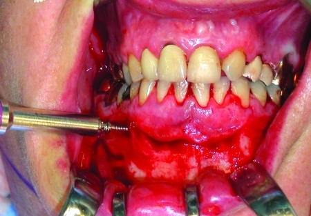
Figure 10.
Insertion of a self-drilling MMF screw after exposure of the bony surface into the bucccal interradicular space between the first and second premolar in the lower right quadrant during open reduction of a parasymphyseal (left) mandibular fracture.
Figure 11.
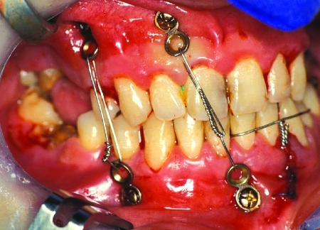
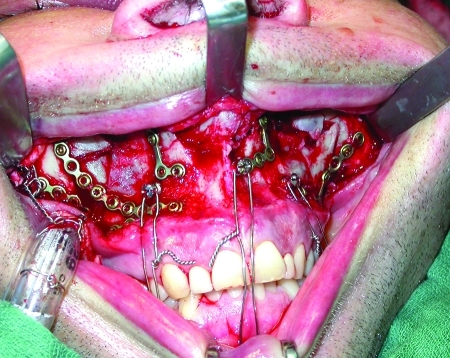
Lateral four point MMF during open reduction of a mandibular angle fracture. (A) Frontal overview. (B) Detail right mandibular body and angle exposed, locking plate fracture fixation. Transbuccal trocar still in situ. (C) Detail left vestibulum. Convergent angulation of the screws requires to thread wire loops through the ligature holes in the screw heads to prevent them from slipping off.
Figure 12.
Temporary MMF (lateral and frontal) during open reduction and fixation of a fracture in the anterior mandibular body. Space limitations for osteosynthesis material (i.e., tension band plating) must be considered prior to the MMF screw insertion.
Figure 13.
Temporary MMF (frontolateral) during open reduction of a fracture at the Le Fort I level. MMF screws in the upper jaw were inserted after bone exposure. The riding of the medial wire cerclage over the incisal edges was accepted. The endotracheal tube is fastened to an additional MMF screw in the zygomatic body above the fracture lines. The application of a full dental arch bar in the mandible had been hardly possible due to the deep frontal overbite.
Figure 14.
Anterior open bite deformity and Le Fort I fracture (exposed and partially plated). Three point frontal and lateral MMF with screws and wire loops. Exclusive frontal MMF most likely had resulted in posterior nonocclusion and bony malalignement.
Figure 15.
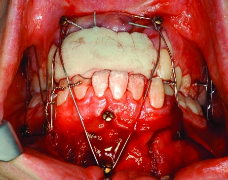
Triple mandibular fracture: bilateral subcondylar process fractures resulting in loss of vertical ramus height and left parasymphysis fracture. Avulsion of all upper incisors. Occlusion reduced and secured with an individualized pattern of conventional cortical bone screws and cerclages after immediate replacement of the lost upper incisors with a ready made block of silicone impression material creating a supporting platform.
In a transmucous procedure the soft tissues (gingiva, vestibular mucosa) can be punctured with an electrocautery needle, a No.11-blade scalpel or a 1-mm punch at the insertion point. When the screws are passed through an excessive amount of moveable mucosa, the exact entry point into the bone will be uncertain. Reseating the MMF screw when it has lost contact with the bony hole concealed by abundant mucosa can be difficult.
Holes for self-tapping MMF screws can be drilled with a slow-speed hand-piece under copious irrigation directly through the thin mucoperiosteal layer. The mucogingival junction is the most appropriate site for this procedure.
The burr is passed through the outer cortex, the medullary space and optionally into the lingual or palatal cortices, depending on whether a monocortical or bicortical placement is desired. The burr hole reduces the force needed for the insertion process.
Self-drilling MMF screws are commonly driven into the bone by hand without any preparation. The thickness of the outer cortex determines the insertion force of the drive tool. Insertion starts with unengaged turns on the bony surface before the screw tip breaches the cortical shell and engages. After piercing the outer cortex, resistance drops abruptly with entry into the spongy bone, then the screw is pulled into the bone by rotation resembling a corkscrew.14 If no change in resistence becomes noticeable, a tangential gliding along dentin of a tooth root or a complete penetration into a root is likely and removal and reinsertion of the screw in a new direction must be considered.14,15
If the thickness of the outer bone cortex exceeds 2.5 to 3 mm, predrilling through at least the outer layer is recommended. The MMF screws should then be inserted with well-balanced and harmonious rotary motions exerting a moderate amount of power continously. Vigorous, off-centered driving of the screws will wear the bone eccentrically and compromise the grip of the threads.
With bicortically placed MMF screws it is important that the screw tips fully penetrating the inner cortical layer and reaching into the lingual or palatal mucoperiosteum do not become a tangible nuisance for the patient's tongue. This is excluded by finger palpation.
The position of the ligature holes in the screw head is indicated by the cruciform recess of the screw drive. To make the ligature holes easily accessible it is better to back out the screw a little into the desired position than overtightening the screws and risking to strip the threads.
For a secure grip of the screws, it is not necessary to insert the screw shaft over the full length until the shoulder portion of the MMF screw head firmly compresses the mucosal layer (Fig. 7). Soft tissue necrosis around the entry hole by excessive compression should be avoided. Satisfactory holding power is usually achieved if at least two-thirds of the screw shaft has entered the bone, provided there is good quality bone of substantial thickness. The stability of each individual screw should always be checked. Although transmucous MMF screws show resemblance to osseointegrated dental implants, perimucositis and periimplantitis are usually not an issue during a short period of use. If possible, the screw heads should not be submerged into moveable mucosa.
Once a sufficient number of MMF screws have been inserted, then the occlusal relationships are precisely adjusted, possibly improving the bony reduction. The ends of the cerclage wire are passed through the ligature holes in the screw heads and twisted under a constant pull with intermediate tugging motions until the wire loop is straight and fully tightened. If the screw axes opposite in the jaws are oriented at divergent angles direct looping of the wires around the screw head grooves will be possible. A convergent angulation will cause the ligatures to slip off the screw heads and make it mandatory to use the milled ligature holes (Fig. 11C).13,14
More MMF screws can be added at any time to provide additional anchorage and to reinforce the rigidity of the fixation prior to plate and screw osteosynthesis. To reestablish correct preinjury occlusion, both condylar heads are comfortably seated into their fossae manually, distraction of the condylar heads out of the condular fossa will produce malalignment following the release of IMF.
Removal of MMF screws after completion of therapy is simply done by a screwdriver. After a long-term transmucous placement, the screws can be taken out without local anesthesia in the clinic. The small wound which is left closes or granulates spontaneously within a few days. Screws buried under soft tissue may be exposed under local anesthesia and removed. Leaving buried but protruding MMF screws in place, as performed in one early study, is not recommended.16
INDICATIONS AND CONTRAINDICATIONS
MMF screws can provide bone anchors during establishing and maintaining the occlusion in a wide variety of fracture patterns involving the adult maxilla and mandible. The absolute requirement for the use of MMF screws, however, is the existence of a stable occlusal platform to keep the occlusion in the preinjuy relationship when wire cerclages are placed across the screw heads and tigthened for fixation. This holds equally true for closed and open treatment of fractures. When IMF is to be employed for long term, an appropriate MMF screw type should be selected with a broad basal disc that redirectes wire ligatures or elastics away from the tooth surfaces (Table 1).
Favorable conditions include simple fractures of the fully dentate mandible and/or maxilla, since it is easy to construct a stable mandibulo-maxillary unit by the insertion of a few MMF screws and wire links (Figs. 11 and 12).
Fractures of the alveolar process can be realigned and retained in place through bone contacts. The alveolar process itself may need stabilization by dental splinting as well (e.g., acid-etch/resin Kevlar, fiberglass, or metal lightcuring splints), small plate osteosynthesis or both for double reinforcement, especially if alveolar fragments are freely moveable. Whereas traditional arch bars serve as anchor points for intermaxillary wire loops and splinting at the same time, MMF screws do not.
In fractures of the maxillae extending into the palate either in a sagittal direction (median or paramedian) or in a comminuted pattern the tooth bearing arches must by prevented from tilting, collapsing, widening, or flaring. “Side-to-side” stability of the maxillary arches17 can be achieved in various ways (dental model casted acrylic palatal splints, transverse intermolar wiring, open or transmucous rigid stabilization of the palatal vault). It is mandatory to restore the integrity of the upper jaw prior to the use of MMF screws. Transverse palatal fractures do not require complementary steps because splaying of the maxillary occlusal plane may be prevented reliably via coupling across MMF screws to an intact or repaired mandible.
Multiple fracture sites within the jaws and the absence of opposing teeth complicate the reassembly of bony bases of the mandible and maxilla. The interconnection by MMF screws and wire must be supplemented by open reduction. If it is possible to rebuild supporting occlusion with dentures,18 impression material (e.g., polyvinyl-silicone, polyether, etc.) (Fig. 15), or prosthetic tray material (self-curing, light curing, or thermoplastic), partially or completely edentulous fragments can be captured with the help of MMF screws and held in their original anatomic position (Fig. 16). It does not matter if the tooth loss is caused by the trauma or preexisting atrophy.
Severe bone atrophy as in pencil thin mandibles and/or in osteopenic and highly pneumatized maxillae are not suitable for MMF screws, because the remaining bone will fail to provide a secure purchase for the screws.
In some facial fracture scenarios (i.e., Le Fort II and III patterns, panfacial fractures, multifragmentation of the mandible including the condylar processes) a mandibulo-maxillary unit may be created and locked together by MMF screws and wire ligatures. This unit can be manipulated in the comprehensive repair process as a single element and integrated into the outer facial frame by auto rotation once the ascending rami and condyles are stabilized.
In comminuted and defect fractures priorities are given to anatomic reduction of the existing bone and with bridging hardware of the skeletal gaps. The applicability of MMF screws here is related to the occlusal matching of the counterparts left in the jaws. Only large uninterrupted bone portions are suitable for MMF screw insertion (Figs. 17 and 18).
Figure 18.
Horsekick injury of the right lower face with extensive soft tissue laceration and complex mandibular body fracture icluding the alveolar process. (A) Fragments still unreduced, first MMF screws and wires applied. (B) View through the soft tissue wound. Anatomic bone reduction and occlusion maintained by a few MMF screws in conjunction with interarch and circumdental wire loops. Right mental nerve traumatically torn off.
In dentofacial deformities or in preinjury skeletal discrepancies with malposition of the teeth, the usefulness of MMF screws must be individually evaluated. Generally speaking, skeletal malocclusion due to pure anteroposterior or sagittal irregularties (Angle class II with positive overjet or class III with negative overjet) is compatible, while vertical abnormalities with a tendency to open bite are frequently not compatible (Fig. 14). Localized fragments lacking occlusal contact can be displaced by attempts to use IMF screws, interfering with anatomic reduction.
Pathological bone quality must be regarded as a contraindication to the use of MMF screws. Problems arise as the purchase of the screws is compromised by thin cortices, reduced bone density or brittle, fragile bone as occurring in osteoporosis,19 and congenital or acquired osteopathies.
Injury to unerupted tooth buds and dental follicles should be avoided. Passing MMF screws through these structures may cause infection, impingement and rotation of the tooth buds leading to inflammatory resorption, osteomyelitis, impaction, growth arrest or retardation, and deficient or abnormal root formation. Thus MMF screws may be contraindicated in children with deciduous or early mixed dentition. In the later stages of mixed dention the anterior alveolar ridges and their bases become accessible for the insertion of MMF screws. It may be beneficial to apply spino-mental hooks adjoined to MMF screws. In the buccal maxillary and mandibular segments, the replacement of the deciduous teeth by eruption of permanent teeth will occur at an age range of 12 to 14 years.
Congenital or acquired bleeding disorders might lead to persistent oozing from the screw insertion site. Patient options for long-term use of MMF screws must be individually evaluated according to the risk of thromboembolic complications and the justification for modifications of the medication.
For open fractures, temporary cessation of oral anticoagulation is often necessary. If the MMF screws are kept in place beyond the healing period of the surgical access site, the reinitiation of anticoagulation may be delayed. Mandibulo-maxillary fixation postoperatively is generally contraindicated in epilepsy, chronic alcohol and substance abuse, obstructive airway disease, psychiatric disorders, gastric reflux, and anorexia/bulimia.
COMMON PROBLEMS
Common problems encountered with MMF screws relate to the three issues:
Risk of injurying tooth roots
Soft tissue burying of screw heads in the anterior mandibular vestibulum19
Interference of wire loops with the upper incisor edges or canine facettes
MMF screws can penetrate dental roots and cause defects.20,21
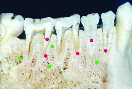
Based on the two-dimensional projection in panoramic x-rays or dental films, dental root defects are classified according to their location, size and prognosis for survival of the injured tooth (Fig. 19). Fabbroni et al22 distinguish minor from major contact root injuries depending on the percentage of the circumference of the hole left by an MMF screw radiographically visible adjacent or over the root formation. The threshold value to separate minor from major lesions amounts to a 50% overlap between screw hole and the dental root (Fig. 20). In a retrospective radiographic study on screws used for monocortical miniplate fixation of mandibular fractures using Champy's technique, Driemel et al23 characterize four types of dental root lesions. Two “central” types comprise lesions above or in the apical third of the root (including the neurovascular bundle) presumably including a pulp injury. The two “peripheral” types are not associated with pulp injuries and are located either in the radicular dentin, cement, or peridontal space
Figure 19.
Sagittal cut through dentate right mandibular quadrant with schematic markings of the suitable sites for MMF screws in the subapical region or the interradicular spaces (green dots) in contrast to the various types of dental root lesions (red dots). The dental roots are divided into thirds as a reference for the vertical height (blue parallel lines). Radiographically the innocuous “peripheral” types of root lesions are located in or over the dentin or cement and do not involve the pulp (see first and second molar). The severe “central” types project over the pulp chambers (see first and second premolar) or the neurovascular entry zone at the tooth apex suggesting a deleterious hit.
Figure 20.
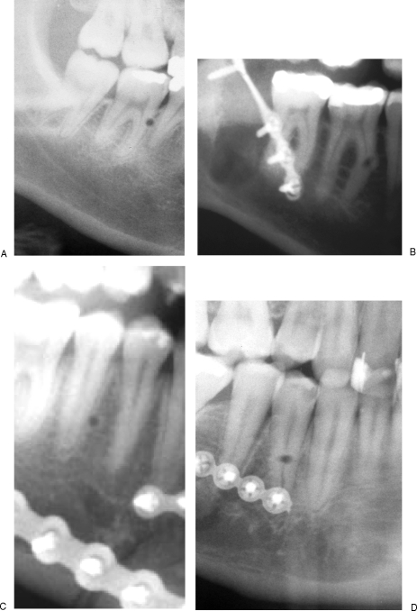
Radiographs showing several types of dental root lesions after MMF screw removal. (A) “Minor” peripheral lesion along the peripheral dentin in the upper third of the mesial root of the right mandibular first molar. (B) “Major” central lesion in the middle third of the mesial root of the right mandibular first molar. The image did not clarify possible pulp involvement. CO2 vitality testing was positive. (C) “Minor” peripheral lesion next to the periodontal space in the middle third of the root of the second right mandibular premolar. (D) “Major” central lesion in the middle third of the root of the first right mandibular premolar.
Both studies found that the occurence of major radiographic lesions was not reliable in predicting clinical sequelae in terms of vitality testing or the necessity for endodontic treatment, apicetomies or tooth removal. This was explained by the radiographic assessment technique (periapical dental films or panoramic radiographs), which cannot reveal the actual depth of penetration or the involvement of the dental pulp chamber (Fig. 21).
Figure 21.
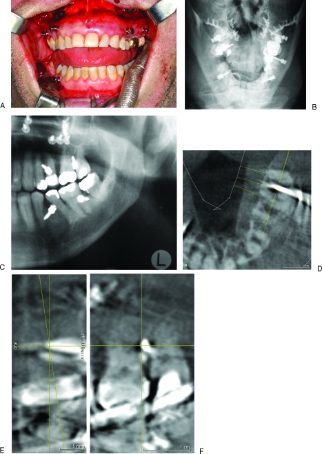
Possibilities of postoperative radiographic assessment of MMF screws positions exemplified after four-point interarch wiring behind the canines for treatment of a Le Fort I fracture. (A) Final intraoperative check of occlusion subsequent to release of wire cerclages. MMF screws left in situ. (B) Occipito-frontal skull x-ray view (Towne's) of the Le Fort I level. The MMF screws overlap with the tooth roots. (C) Panoramic x-ray of second and third quadrants. MMF screws pairwise in the larger interradicular spaces of the mandible and maxilla. The screw position between the upper first and second molar was three dimensionally evaluated in cone beam (= digital volume tomography scans). (D) Axial DVT plane of the second tooth quadrant. The shaft of the MMF screw goes straight through the interradicular space without any root contact. (E) Coronal DVT plane. The tip of the MMF screw does not reach the palatal cortex. Difficulties in interpretation may arise from the blurring artifacts caused by stainless steel screw material as in this case. (F) Sagittal DVT plane—at the level indicated by the diagonal yellow line in D. The distances between the screw shaft and the tooth can be precisely measured in serial planes
Grooving, scoring, or scratching the surface of tooth roots peripherally at the cemental lining is reported to have innocuos consequences. Recent histological examinations in experimental root lesions induced with orthodontic mini screws (diameter 1.7 mm) in beagle dogs demonstrated a nearly complete repair of the periodontal structures (cementum, periodontal ligaments and bone socket) starting 12 weeks after removal of the screws.24
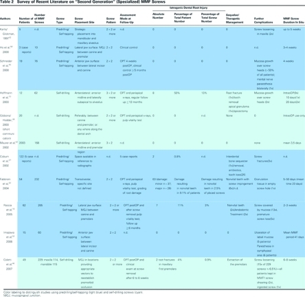
The percentage of tooth root injuries per patient after MMF screw placement regardless of their severity and clinical relevance was pointed out to range over more than 10% (Table 2). This number probably exceeds the incidence of root damage caused by screws inserted for plate osteosynthesis; however, the calculation base differs between the reports and renders comparisons difficult. Thus Borah and Ashmead25 documented an incidence of 0.47% for root impingement per screw (13 transfixed teeth per 2340 screws) subsequent to monocortical or bicortical plate osteosynthesis in the facial skeleton, while Driemel et al23 indicated a percentage of 1.4% per screw (30 out of 2100 screws), but in 8% of their overall patient series (29 out of 380 patients).
If damage of the mandibular or maxillary tooth roots by a central pulp involving lesion is identified on postoperative x-rays after the use of MMF screws (Figs. 21 and 22) a follow-up period of 4 to 6 months is good clinical practice. Endodontic treatment is administered only if vitality testing (repeated at regular intervals) remains negative or if the affected tooth becomes symptomatic, i.e., pulpitis.
Figure 22.
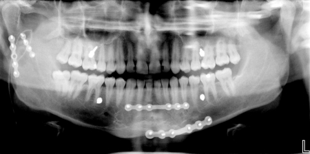
Immediate postoperative panoromic x-ray with 4 MMF screws left in place after previous use during open reduction and plate fixation of a double mandible fracture: parasymphyseal region left in combination with subcondylar region right. Ironically enough the screws of the superior border miniplate in the front project onto the root tips of the lower incisors. The MMF screw in the lower right quadrant (between second premolar and firstmolar) needs clinical and radiologic control to rule out damage and confirm the integrity of the root/pulp.
Several case reports dating from the late 1990s and early 2000s focus attention to intraoperative technical problems during MMF screw insertion such as bent or fractured screws and shearing of the screw heads.26,27 A rare event is fracture of tooth roots affected by MMF screws engaging so heavily into the radicular substance that their shafts break. Osteotomies may be required for removal of the foreign body and tooth.26
Inadvertent penetration of the MMF screw shaft or tip into the maxillary sinus does not matter and will heal spontaneously unless the antral wall is thin and fragile. The MMF screw will get loose and tilt downward when the wire cerclages are applied and tightened. A small circle-shaped impaction or lamellar cracking of the antral wall together with a soft tissue laceration may result in a vestibular oroantral fistula and if persistant may require surgical closure.
All three kinds of damage from MMF screws listed can be controlled when the lateral sides of the mandibular and maxillary alveolar ridges posterior to the canines are selected as the sole sites for screw placement. The risk of hitting the apices of the tooth roots with deleterious consequences for pulp survival is noticeably diminished using the interradicular/interdental spaces. Screw heads covered by soft tissue do not present an issue anymore since the necessity to place MMF screws into mobile mucogingival tissue is almost always confined to the anterior vestibulum of the mandible. Finally, wire loops around MMF screws located in the premolar and molar region will easily bypass these teeth and resolve the problem of undesirable interferences with upper incisors or canines.
DISCUSSION
The insertion of MMF screws is a rapid and elegant technique to provide abutments for jaw immobilization with wire or elastic loops and secure occlusal relationships. MMF screws are claimed to improve the safety of the procedure, since only a few wire ligatures are used as jaw linking cerclages. Minimizing intraoral manipulation with sharp stainless steel wire tips diminishes the rate of glove perforations and puncture injuries as risk factors for blood borne virus transmission (hepatitis B, hepatitis C, HIV).28 Therefore the application of wires with blunt ends rounded by laser welding, heavy traction elastics or orthodontic powerchains around the MMF screws offers even more effective infection control.13,14 An incidence of glove perforations up to 50% due to wire stick trauma was reported, when intermaxillary wire fixation was employed as the single treatment modality in a series of mandible fractures.29
A lowered incidence of glove perforations using MMF screws has been confirmed in a pilot clinical study16 with a 9:1 ratio of glove penetrations in arch bars compared with no penetrations in MMF screws.
Arthur and Berardo20 are acknowledged to be among the first to propose the use of conventional 2.0 mm self tapping titanium bone screws directly linked by wire loops to establish mandibulo-maxillary fixation. This direct connection over the screw heads was preceded by 2.0 bone screws equipped with J- or S-shaped metal hooks serving as indirect attachment points. These specially designed hooks made of 0.8 mm Cr-Ni steel wire with a ring bent at their base for passing through the bone screw were introduced 1981 by Otten8 and are referred to as “Otten hooks.”30,31,32 In the original technique the screws were placed submucously at the midline of the maxilla and mandible next to the anterior nasal spine and into the mental protuberance, respectively. The metal hooks protruded into the anterior upper and lower vestibulum acting as supporting elements for elastics or wire ligatures to accomplish a spino-mental fixation. Lately, the “Otten hooks” have found renewed interest as a form of conservative therapy for mandibular fractures9 and in particular for the closed treatment of condylar process fractures. The bone anchored mandibulo-maxillary immobilization with conventional cortical bone screws was showcased in several reports during the 1990s.16,18,33,34,35,36,37,38
Numerous and distinctive advantages over traditional methods were highlighted:
The simplicity of technical handling
The ease and speed of application resulting in abbreviated operating times and cost-effectiveness
A low risk of inadvertent skin punctures with decreased risk of transmission of viral pathogens
High stability of skeletal anchorage for precise realignment of the preinjury occlusion when the dentition is preserved
Minimal amount of hardware in the oral cavity, improved comfort for the patient and improved oral hygiene
Suitable for application in extensive prosthodontic restorations with crown and bridgework or full dentures
Compatibility with open reduction and bone plating osteosynthesis
Painless and fast removal in the office
Conversely, the problems, risks and complications of MMF bone screw technique were minimal in these intial papers and dental root injuries seemed hardly worth mentioning. The number of patients studied ranged from two illustrative cases18 over 10,37 13,36 and 23,38 2916 to reach 67 in the reports of a consecutive series after a 2-year experience.33,34,35 These small patient groups treated by experts might contribute to the low occurence of problems and to overenthusiasm with neglect of shortcomings.
Except for two reports,36,38 which employed the screws intraoperatively only prior to open reduction and plate fixation, the screws were used for MMF in closed fracture treatment for long-term immobilization. The number of screws or fixation points (2, 4, 6, and 8), the diameter (2.0, 2.4, 2.7, and 3.5 mm) and the screw length (10 to 24 mm) varied widely across the studies as well as the mono- or bicortical insertion mode. The preferences for screw placement were two anatomical orientations at the anterolateral or lateral jaw surfaces: Conforming to the original description of Arthur and Berardo,20 the anterolateral surface of the maxilla in the piriform rim and at the zygomatico-maxillary crest and the anterolateral mandibular region below the root apices and between the mental foramina.16,18,33,35,38 The anterolateral screw sites were described as the distant cranial or caudal alveolar processes away from the root apices, medial or distal to the canines.34,39
The alternate choice at the lateral surfaces were the spaces betweeen the first and second premolars in each quadrant36 or along the entire mucogingival junction.37 MMF bone fixation in adults with permanent dention was done in 72 patients by use of four Mitek Mini anchors placed transmucosally mesial to the canine tooth roots and bilaterally into the pyriform rims.40 The Mitek anchors in the opposite jaws were attached with suture ligatures stretching an intermediate bundle of heavy orthodontic elastics. If complete upper and lower dentures are available, the Mitek skeletal MMF anchor technique can be employed in edentulous jaws. In primary or mixed dentition a set of four peculiar “microlugs,” each composed of a two-hole segment of a thin Vitallium mesh and a microscrew of 3 mm length were applied monocortically mesial to the secondary canine follicles. For the treatment of pediatric mandibular fractures a resorbable MMF screw placed in the anterior zygomatic body in combination with a nonresorbable circummandibular monofilament suture has also been used for fast MMF.41
The overall positive response to MMF bone anchoring techniques fostered the design and manufacturing of specially designed or dedicated MMF screws.42,43,44,45 These “second-generation MMF screws”46 had polished and smoothed capstan-style heads with milled channels for the uptake of the ligature wires to minimize damage to the labial mucosa and increase the patient's comfort. At first the MMF screws were self-tapping and later on self-drilling.14,47,48 Self-drilling MMF screws are hand inserted without predrilling and do not need power equipment. This provides additional safety against contamination by infectious aerosols and blood or saliva splashes generated during drilling with handpieces28 and avoids thermal necrosis of the bone or the mucosa.
Compared with predrilling of holes self-drilling MMF screws are presumed to offer an improved tactile feedback as soon as tooth roots are encountered.46,48 This barely verifiable feature is supposed to permit a prophylatic screw removal, redirection of the entry path or repositioning to another site.
Self-drilling MMF screws48 can be applied at the bedside.49 The market launch of the specialized MMF screws in the late 1990s was followed by journal publications, technical notes, and short communications, demonstrating the features of the new equipment.14,42,43,47,48,50 The potential risks were raised by a succession of clinical studies and case reports (Table 2). The methodology and the quality of documentation in these studies barely exceeds an empirical level of evidence, but the data reveal the occurence and frequency of complications, which must be acknowledged. The detection of tooth injuries must be determined by the adequacy of assessment in follow up as well as the precise determination of the relevant lesion (see above for full description). Only those reports with a rigorous clinical (vitality testing) and thorogh radiographic protocol describe significant percentages of root damage per total number of applied screws, reaching from 0.9% to over 3% up to an alarming 13%.13,19,22,46 A minority of the injured teeth required endodontic treatment, apicectomies or removal, since the injuries were either peripheral or did not end inside the pulp chamber.
Screw loosening was noticed on 6.5% (15 out of 229) of the screws placed in the most recent report.46 Hardware failure is attributable to prolonged periods (2 to 8 weeks) with wire linkage and/ or guiding elastics. It suggests a compromised stability, if a limited number of MMF screws are used as anchor points which has to withstand continuously repeated loading or elastic traction.27,43,51 Fatigue fractures of the screws have not been reported.
Soft tissue burying or mucosal overgrowth of MMF screws (Figs. 23 and 24) is only encountered in studies with screw placement adjacent to or within the mobile mucosa.13,19,45 In the “second generation” studies the screw site selection was based on clinical and radiographic information. About a half of the studies adhered to the anterolateral and lateral locations previously described, while others choose alternative sites to reestablish the occlusion and did not limit any anatomical region (Table 2 and Fig. 25).
Figure 23.
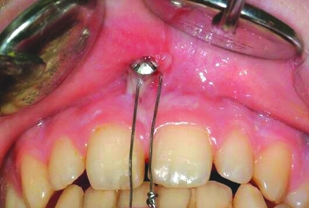
MMF screw positioned in base of the upper labial frenum triggering granulation and burying in the mobile soft tissues.
Figure 24.
Excessive granulation tissue reaction around Otten hooks and elastic loops applied for closed treatment of a subcondylar fracture on the right. A partial acrylic plate was placed in the first quadrant to provide a posterior fulcrum intended for reduction of the condylar fragment. The functional consequence is a circular open bite. The upper central incisors have been protruded and rotated inward by the elastic bands “cutting” into the gums and the interdental spaces thus lifting the teeth forward.
Figure 25.
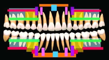
Synopsis of placement sites for specialized (“second generation”) MMF screws as described in the text and listed in Table 2. The MMF screw insertion sites of the different study groups are superimposed symmetrically on a panoramic display of the upper and lower quadrants. For improved visualization the exit zones of the mental nerve and its branches around the foramen are not spaced in the scheme. (Color-coded fields—authors: Blue—Otten 19818; Pink—Schneider et al,45 Imazawa et al53; Magenta—Ho et al50; Blue and red—Hoffmann et al13; Blue and yellow—Maurer et al52; Green—Karlis and Glickman42; Yellow—Roccia et al19; Gray—Fabbroni et al22; Orange and gray—Coletti et al46)
The placement of MMF screws in those studies correlated with utilization of open reduction techniques.13,14,46,51 Open surgery in conjunction with rigid plate and screw fixation allows immediate removal of MMF screws from tactically efficient but uncomfortable sites at completion of surgery; in long-term closed treatment, screw placement has to account for the physcial comfort of the patient.
Rare incidents were also noticed, namely bone infection and interdental sequestration,27 root fractures,13 pressure ulcers of the mucosa overlying the screw heads and cerclages,53 sensory disturbances or deficit in the innervation of the inferior or mental nerves,45,53 breakage of drill bits,14 deflection or shearing of screw shafts, fracture of screw heads27 and screw ingestion.46
The clinical studies are supplemented by letters and replies further elucidating the MMF screw technique45,47,51,54,55,56,57 and its adverse sequelae.26 In regard to the danger to dental root injuries skepticism and caution against the use of MMF screws was notoriusly prominent.15,21,58,59
From the very beginning the domain for MMF screw utilization has been seen unanimously in the treatment of so called “simple” (i.e., singular, one line, nondisplaced) fractures in the mandible and maxilla or both. The indication in closed treatment33,34 has been expanded with the progressive use of internal fixation devices. Generally speaking in adults there are no absolute contraindications42,48 for the temporary or postoperative use of MMF screws, even in alveolar process fractures, comminution or partial or complete edentulism. Whenever a satisfactory three-dimensional relationship of the bony bases and jaws can be restored using dentures or bite blocks as a platform, MMF screws may anchor fragments until rigid plate fixation is accomplished.
Unerupted tooth buds in the deciduous or mixed dentition of pediatric patients are a danger—potential injury by MMF screws presents a compelling contraindication to their use. Comparisons of traditional arch bars or chain-linked wiring and MMF screws have been made since the introduction of the latter. Directly applied arch bars (such as Erich arch bars, used in the United States), combined wire arch and cold cure acrylated Schuchardt-splints (used in Europe) or custom-made laboratory arch bars are still considered the gold standard in MMF techniques. Because MMF screws cannot offer the same properties or functions as arch bars, the missing features are judged as a deficiency. Prior to reinforcement with acrylic metal arch bars provide a contiguous but flexible connection along the teeth, which was helpful in the spatial reapproximation of fragments. The interdental metal bar is capable of bridging edentulous spaces in the mandibular or maxillary arch and of capturing loose teeth, tooth-bearing alvolar processes, or segmental mandibular or maxillary fragments. This “string-like” coupling allows for manipulation (sideward/upward/downward bending, torque) for occlusal readjustment and bone reduction.
In addition to internal plating in the mandible, arch bars can serve for tension banding and provide an extra line of resistence to the overall hardware construct. However, the function of converting tensile into compressive forces can also be efficiently performed by a superior border osteosynthesis plate.
Arch bars are wired around the tooth necks so that their hooks lie at or closely below the level of the vestibular interdental papillae. This hook position reduces the magnitude of the eccentric forces, which are responsible for the tilting of the bone fragments to the lingual side upon wire or rubber band anchorage. The placement of MMF screws into the interdental bone spaces nearby the alveolar crest will have a similar effect and assist to prevent malocclusion caused by “bucco-lingual rotation.”
The drawbacks of arch bars are the reverse of the advantages of MMF screws: difficult to handle, associated with prolonged operating time, high risk of wire stick injuries with viral infections, instability (arch bars come off), pain and discomfort to the patient, compromise of oral hygiene,60,61 trauma to periodontium,62,63 inducing demineralization of dental enamel and caries (Fig. 26), questionable risk for allergic reactions due to galvanic metal,64 interference in CT imaging, incompatibilty with MRI and removal procedure uncomfortable to patients. Some of the technical shortcomings of arch bars (the danger of tooth avulsion, crown fractures and the exertion of orthodontic forces leading to tooth extrusion) are related to the skill and experience of the surgeon. Difficulties will occur in advanced periodontal disease, where the remaining teeth are loose and inappropriate to carry an arch bar.
Figure 26.
Neglected oral hygiene and rampant dental caries after long-term use of laboratory made full arch bars over a 4-week period for closed fracture treatment. (A) Arch bar prior to removal. (B) Circular caries around the cervical portion of the upper central incisors will require restoration with composites or crowns and perhaps root canal treatment.
Excentric loading of a full mouth metal ceramic or metal resin implant restoration with arch bars may create problems. Furthermore, retrusion of the mandible in conjunction with a deep frontal overbite precludes the application of a classic arch bar (Fig. 13).
A pragmatic answer to the pros and cons of cortical bone screws versus arch bars is to accept that these methods represent two divergent anchorage principles, skeletal versus tooth borne, and will coexist with each other. Both methods have a decade-long history and the time-honored versions should undergo and eventually profit from refinements and diversification in design and application.
In the constant pursuit of improvement, arch bars (laser cut titanium)65 and button-like tooth-borne appliances (Rapid IMF™—circumdental flexible nylon straps providing fixation points)28,59 have been introduced recently. Simultaneously a large body of knowledge on miniscrews and miniplates for temporary skeletal anchorage in orthodontics has grown.66,67,68,69,70,71 The analogy to MMF screws will open up valuable new insights. In this context the capability of a specialized screw formerly employed for MMF52 has been preliminarily evaluated for orthodontic anchorage.72
The indication for prolonged periods of MMF today is much less than previously. The use of long-term MMF focuses chiefly on the closed treatment of mandibular condylar process (subcondyle, neck, head) fractures. This is usually instituted with guiding elastics, since mandibulo maxillary immobilization by way of rigid wire cerclages is considered counterproductive for rapid restoration of function.73,74 A few studies investigating the omission of perioperative MMF by arch bars in favor of manual reduction in the surgical management (ORIF) of mandibular fractures did not achieve persuasive results.75,76,77
As a routine, internal fixation procedures are still accompanied by short-term intra- or perioperative rigid MMF. Temporary as well as prolonged MMF requires primary stability of the bone screws. Loading by wires loops or rubber bands is perpendicular (transverse) to the screw axis and may lead to displacement, migration, or flexural deformation depending on the screw design, dimension bone purchase, e.g., mono- or bicortical. The loading characteristics differ in their patterns, intensity and duration. Intraoperatively under skeletal muscle relaxtion the loading of MMF screws is determined by the traction along the wire or elastic exerted by the surgeon and reaches a steady state when the jaws are finally closed in occlusion. In prolonged MMF when training elastics are used, the screw stability has to tolerate a dynamic range of loading cycles during mandibular opening.
So far, no benchmark parameters for MMF screws have been established to make them match with the diverse biomechanical conditions of one time and perpetuated transverse pullout. The mechanical performance as well as the safety profile of MMF screws can certainly be optimized by adapting their length and diameter to the specific demands. The incorporation of several screws into a unit will provide stability against dynamic loading. Clinical testing of modifications of the screw head design predicts a shape that does not produce discomfort.
The ideal “shoulder disc” or “collar” of the screw head should not only avoid soft tissue irritations and contribute to the patient's comfort but redirect the wire cerclages away from tooth interference by redistributing the vector of the linkage between the jaws. If elastic guidance becomes necessary, for example, a spacious collar is certainly valuable in directing the loops into the vestibulum and keeping them from rubbing against the tooth edges.
Injuries of the periodontal tissues with mobile teeth, intra-alveolar root fractures, or dento-alveolar trauma in addition to fractures of the mandible or maxilla necessitate tooth splinting besides MMF. Rigid tooth splinting by way of circumdental wiring is an integral feature of the traditional arch bars. In dental traumatology rigid tooth immobilisation has been abandoned since the 1980s in favor of adhesive bonding techniques.78,79 To achieve interdental stabilization, kevlar, fiberglas, or wire (-mesh) composite splints have been proposed, because they grant varying degrees of physiologic micromovements, which promote periodontal healing.80 Thus a combination of adhesive dental splints and MMF screws appears logical in some fractures.
The use of MMF screws is technique sensitive as screws go where the surgeon places them,56 that the more MMF screws are used the more tooth roots will be at risk for injuries.
None of the MMF studies mentioned above clearly demonstrates a relationship of the screw placement site and the occurence of serious tooth root injuries, but the topography with variations in root morphology and size is the decisive factor in dental root lesions apart from the screw design and the surgeon's skills. Because the dental root lesions are responsible for the greatest criticism of MMF screws19 a rationale for a precautionary screw site selection is preferred (Fig. 27). There is no absolute safety technique to prevent iatrogenic damage of dental roots, but the hazard can be diminished. Anatomic danger zones like the mental foraminen, the neurovascular bundles within the areas of nerve exit, and the mandibular canal or the maxillary antral wall are the first constraint for MMF screw placement.
Figure 27.
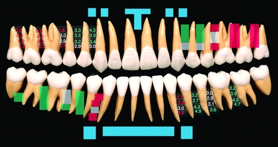
MMF screw insertion sites according to current concepts. Along the anterior surface of the mandible and maxilla the MMF screws are introduced into a sub- or supra-apical position (blue markings). The anterior/frontal surface should be reserved to MMF screws assembled with hooks (e.g., modified Otten hooks). The interradicular spaces behind the canines appear as the best choice for MMF screw placement as outlined in the discussion. The results of Poggio et al81 predict the mesiodistal interradicular spaces along the lateral side of the mandible (lower right quadrant) and maxilla (upper left quadrant) are color coded to indicate the safety of MMF screw placement with a maximum of 1.2 mm (green squares = low risk or ‘safe zones’; gray squares = intermediate risk for root damage; red squares: incompatible with 1.2 diameter MMF screws). The measurements were performed at four incremental distances (2, 5, 8, and 11 mm) away from the alveolar crest. The correlating values are shown in the first and third quadrant in identical color coding.
A second premise is that most interradicular spaces are more reliably recognized due to the prominent juga alveolaria than are the root tips, which are usually hidden under an even bony layer. While the root contours can be readily perceived around the entire maxilla the molar region of the mandible is less predictable because of the thick cortical shell of the oblique line. In other words the width of most tooth roots can be more likely anticipated than their complete length (Figs. 2, 4, and 6). This is against the recommendation to locate MMF screws into subapical or supraapical positions. From a practical point of view interradicular screw placement is also preferable, since it will commonly result in peripheral root lesions. These are less detrimental to the tooth than central lesions, which are more likely induced by screws inserted superior to the maxillary or inferior to the mandibular dental root apices.
Placement of MMF screws into the interradicular spaces of the anterior maxilla turns out to be unfavorable as the space between the central and lateral incisors and the lateral incisors and the canines is commonly too narrow for any of the commercially available screw types. An appropriate interradicular space is in the midline below the anterior nasal spine reaching downward between the roots of the central incisors. The interradicular spaces in the anterior mandible prevent MMF screw insertion because of the dense grouping of the lower incisors and canines.
In the anterior mandible only the subapical region or the bony strip of the chin below the supramental fold can be used for MMF screws, but this area is compromised by the coverage with mobile vestibular soft tissues leading to a burying of the MMF screws and mucosal irritation. With the exception of Otten hooks, the anterior maxilla and mandible should no longer be considered the first choice site for MMF screw placement. This inference is further supported by the fact that the anterior placement of wire cerclages predisposes to a posterior open bite and malocclusion. Critical reasoning points to the lateral alveolar ridges posterior to the vertical canine line as the optimal areas for MMF screw placement. Wire linkage between MMF screws across this area offers excellent control of occlusion since the jaws are shut in maximal intercuspation along vertical or slightly oblique vectors irrespective of the overbite or overjet condition (Fig. 11). The accessible interradicular spaces along the lateral sides of the maxilla and mandible have been defined in terms of safe zones in a recent article by Poggio et al81 mapping the interradicular spaces for the placement of orthodontic miniscrews (Fig. 27).
Based on digital volume tomograms (cone beam) the mesio-distal and bucco-palatal or bucco-lingual interradicular bony spaces of adult individuals were evaluated at increasing vertical levels (2, 5, 8, and 11 mm) away from the alveolar crest for their capacity to house a 1.2-, 1.5-, and 2.0-mm miniscrew leaving a bony clearance of 1 mm to avoid harming the adjacent periodontal apparatus. For the insertion of 1.2 mm miniscrews into the maxilla, the mesiodistal interradicular spaces between the first molar and second premolar, between the second and first premolar and between the first premolar and canine at vertical heights above 5 mm were identified as safe zones. In the mandible the amount of interradicular bone available between the first and second molar as well as between the second and first premolar are labeled as safe for screw insertion at vertical heights between 2 and 11 mm (for further details see Fig. 27). These vertical heights correspond to screw application at the level of the keratinized attached gingiva and the mucogingival junction. It is disquieting to learn from this paper that screws with an outer diameter of 2.0 mm are not regarded as safe for insertion into the lateral interradicular spaces of the maxilla, but the bony clearance of 1 mm from the screw to the periodontium is a possibly excessive criterion. In practice, the surgeon must rely on imaging to yield information on the individual configuration of interradicular spaces to predict the minimal risk for MMF screws.
The future may belong to new varieties of specialized MMF screws, adapted in dimension and design for a “best fit” within different placement sites.
CONCLUSION
There are two basic modalities for anchoring wires or elastics to establish MMF after craniofacial trauma: tooth-borne devices or bone screws acting as skeletal fixation points. Though each method has received positive ratings, neither represents a perfect solution for MMF, and each has problems and drawbacks. MMF screws are more invasive but a powerful means to achieve a reliable temporary (intra- or perioperative) MMF in a time saving and economic manner. It appears pointless to take a conservatice stance in the debate on MMF screws, because the technique is familiar and appealing. Most testers have expressed the intention to continue to use MMF screws and even the most serious warnings of dental root lesions will not stop the use in a clinical routine.
To take full advantage of MMF screws, it is necessary to determine the biomechanical demands associated with their use and to reduce the potential morbidity through design modifications and customized placement according to the indivdual anatomy of the patient and perhaps eventually to image-guided preoperative planning.
References
- Thota L G, Mitchell D A. Cortical bone screws for maxillomandibular fixation in orthognathic surgery. Br J Orthod. 1999;26(4):325. doi: 10.1093/ortho/26.4.325. [DOI] [PubMed] [Google Scholar]
- Paik C H, Woo Y J, Kim J, Park J U. Use of miniscrews for intermaxillary fixation of lingual-orthodontic surgical patients. J Clin Orthod. 2002;36(3):132–136, quiz 145. [PubMed] [Google Scholar]
- Behbehani F, Al-Aryan H, Al-Attar A, Al-Hamad N. Perceived effectiveness and side effects of intermaxillary fixation for diet control. Int J Oral Maxillofac Surg. 2006;35(7):618–623. doi: 10.1016/j.ijom.2006.01.010. [DOI] [PubMed] [Google Scholar]
- Hopkins R, Morris J H. Mandibular fractures: treatment by closed reduction and indirect skeletal fixation. In: In: Rowe NL, Williams JL, editor. Maxillofacial Injuries. Vol. 1. Edinburgh: Churchill Livingstone; 1985. pp. 232–292. [Google Scholar]
- Dalpont G. On the employment of juxtaosseous metal hooks for intermaxillary fixation in jaw fractures. Riv Ital Stomatol. 1965;20:791–797. [PubMed] [Google Scholar]
- Atanasov D T. Intermaxillary transalveolar fixation for treatment of mandibular fractures. Folia Med (Plovdiv) 2003;45(1):30–32. [PubMed] [Google Scholar]
- Briggs R M, Wood-Smith D. A simple technique for intermaxillary fixation. Surg Gynecol Obstet. 1969;129(6):1270–1274. [PubMed] [Google Scholar]
- Otten J E. Modified methods for intermaxillary immobilization. Dtsch Zahnaerztl Z. 1981;36(2):91–92. [PubMed] [Google Scholar]
- Poeschl P W, Ploder O, Seemann R, Poeschl E. Maxillomandibular fixation using intraoral cortical bone screws and specially designed metal hooks (Ottenhaken) in the conservative treatment of mandibular fractures. J Oral Maxillofac Surg. 2008;66(2):336–341. doi: 10.1016/j.joms.2007.06.671. [DOI] [PubMed] [Google Scholar]
- Wolfe S A, Lovaas M, McCafferty L R. Use of a miniplate to provide intermaxillary fixation in the edentulous patient. J Craniomaxillofac Surg. 1989;17(1):31–33. doi: 10.1016/s1010-5182(89)80124-6. [DOI] [PubMed] [Google Scholar]
- Heibel H, Alt K W, Wächter R, Bähr W. Cortical thickness of the mandible with special reference to minipate osteosynthesis. Morphometric analysis of autopsy material. Mund Kiefer Gesichtschir. 2001;5(3):180–185. doi: 10.1007/s100060100290. [DOI] [PubMed] [Google Scholar]
- Isaacs R S, Sykes J M. Maxillomandibular fixation with intraoral cortical bone screws. Laryngoscope. 1995;105(1):109. doi: 10.1288/00005537-199501000-00023. (Letter) [DOI] [PubMed] [Google Scholar]
- Hoffmann A, Mast G, Ehrenfeld M. Verwendung von IMF-Schrauben zur mandibulo-maxillären Fixation [Usage of IMF screws for mandibulo-maxillary fixation] OP Journal. 2003;19:70–75. [Google Scholar]
- Gibbons A J, Baden J M, Monaghan A M, Dhariwal D K, Hodder S C. A drill-free bone screw for intermaxillary fixation in military casualties. J R Army Med Corps. 2003;149(1):30–32. doi: 10.1136/jramc-149-01-06. [DOI] [PubMed] [Google Scholar]
- Farr D R, Whear N M. Intermaxillary fixation screws and tooth damage. [letter] Br J Oral Maxillofac Surg. 2002;40(1):84–85. doi: 10.1054/bjom.2001.0625. [DOI] [PubMed] [Google Scholar]
- Gordon K F, Reed J M, Anand V K. Results of intraoral cortical bone screw fixation technique for mandibular fractures. Otolaryngol Head Neck Surg. 1995;113(3):248–252. doi: 10.1016/S0194-5998(95)70113-3. [DOI] [PubMed] [Google Scholar]
- Chen C H, Wang T Y, Tsay P K, et al. A 162-case review of palatal fracture: management strategy from a 10-year experience. Plast Reconstr Surg. 2008;121(6):2065–2073. doi: 10.1097/PRS.0b013e3181706edc. [DOI] [PubMed] [Google Scholar]
- Win K KS, Handa Y, Ichihara H, Tatematsu N, Fujitsuka H, Ohkubo T. Intermaxillary fixation using screws. Report of a technique. Int J Oral Maxillofac Surg. 1991;20(5):283–284. doi: 10.1016/s0901-5027(05)80156-0. [DOI] [PubMed] [Google Scholar]
- Roccia F, Tavolaccini A, Dell'Acqua A, Fasolis M. An audit of mandibular fractures treated by intermaxillary fixation using intraoral cortical bone screws. J Craniomaxillofac Surg. 2005;33(4):251–254. doi: 10.1016/j.jcms.2005.02.005. [DOI] [PubMed] [Google Scholar]
- Arthur G, Berardo N. A simplified technique of maxillomandibular fixation. J Oral Maxillofac Surg. 1989;47(11):1234. doi: 10.1016/0278-2391(89)90024-4. [DOI] [PubMed] [Google Scholar]
- Key S, Gibbons A. Re: Care in the placement of bicortical intermaxillary fixation screws [letter] Br J Oral Maxillofac Surg. 2001;39(6):484. doi: 10.1054/bjom.2001.0668. [DOI] [PubMed] [Google Scholar]
- Fabbroni G, Aabed S, Mizen K, Starr D G. Transalveolar screws and the incidence of dental damage: a prospective study. Int J Oral Maxillofac Surg. 2004;33(5):442–446. doi: 10.1016/j.ijom.2003.10.014. [DOI] [PubMed] [Google Scholar]
- Driemel O, Staudenmaier R, Buch R S, et al. Dental injuries due to miniplate osteosynthesis. Classification, treatment management, complications, and prognosis. Mund Kiefer Gesichtschir. 2005;9(5):330–335. doi: 10.1007/s10006-005-0638-0. [DOI] [PubMed] [Google Scholar]
- Asscherickx K, Vannet B V, Wehrbein H, Sabzevar M M. Root repair after injury from mini-screw. Clin Oral Implants Res. 2005;16(5):575–578. doi: 10.1111/j.1600-0501.2005.01146.x. [DOI] [PubMed] [Google Scholar]
- Borah G L, Ashmead D. The fate of teeth transfixed by osteosynthesis screws. Plast Reconstr Surg. 1996;97(4):726–729. doi: 10.1097/00006534-199604000-00006. [DOI] [PubMed] [Google Scholar]
- Holmes S, Hutchison I. Caution in use of bicortical intermaxillary fixation screws [letter] Br J Oral Maxillofac Surg. 2000;38(5):574. doi: 10.1054/bjom.2000.0514. [DOI] [PubMed] [Google Scholar]
- Coburn D G, Kennedy D W, Hodder S C. Complications with intermaxillary fixation screws in the management of fractured mandibles. Br J Oral Maxillofac Surg. 2002;40(3):241–243. doi: 10.1054/bjom.2001.0771. [DOI] [PubMed] [Google Scholar]
- Pigadas N, Whitley S P, Roberts S A, McAlister K, Ameerally P, Avery C M. A randomized controlled trial on cross-infection control in maxillofacial trauma surgery: a comparison of intermaxillary fixation techniques. Int J Oral Maxillofac Surg. 2008;37(8):716–722. doi: 10.1016/j.ijom.2008.05.005. [DOI] [PubMed] [Google Scholar]
- Avery C M, Johnson P A. Surgical glove perforation and maxillofacial trauma: to plate or wire? Br J Oral Maxillofac Surg. 1992;30(1):31–35. doi: 10.1016/0266-4356(92)90133-4. [DOI] [PubMed] [Google Scholar]
- Shetty V, Niederdellmann H. Maxillomandibular fixation with minihooks: a clinical evaluation. Oral Surg Oral Med Oral Pathol. 1987;64(6):677–679. doi: 10.1016/0030-4220(87)90167-8. [DOI] [PubMed] [Google Scholar]
- Ito M, Handa Y, Otsukutomi T, Tatema N, Oka N. Application of von Otten intermaxillary immobilisation for infant condylar fracture. J Jpn Stomatol Soc. 1988;37:773–778. [Google Scholar]
- Toth Bagi Z, Ujpal M, Gyenes V. Experience with Otten's maxillomandibular fixation method. Fogorv Sz. 1994;87(3):71–73. [PubMed] [Google Scholar]
- Busch R F, Prunes F. Intermaxillary fixation with intraoral cortical bone screws. Laryngoscope. 1991;101(12 Pt 1):1336–1338. doi: 10.1002/lary.5541011214. [DOI] [PubMed] [Google Scholar]
- Busch R F. Maxillomandibular fixation with intraoral cortical bone screws: a 2-year experience. Laryngoscope. 1994;104(8 Pt 1):1048–1050. doi: 10.1288/00005537-199408000-00024. [DOI] [PubMed] [Google Scholar]
- Busch R F. Mandibular osteosynthesis with intraoral miniplates and cortical bone screws. Ear Nose Throat J. 1995;74(12):814–815. 819–820. [PubMed] [Google Scholar]
- Onishi K, Maruyama Y. Simple intermaxillary fixation for maxillomandibular osteosynthesis. J Craniofac Surg. 1996;7(2):170–172. doi: 10.1097/00001665-199603000-00022. [DOI] [PubMed] [Google Scholar]
- Govoni F A, Pistilli R, Piccolino P, Cassoni A, Matteini C. Maxillo-mandibular fixation by mono-cortical screws. Clinical indications and surgical methods. Minerva Stomatol. 1999;48(3):93–96. [PubMed] [Google Scholar]
- Vartanian A J, Alvi A. Bone-screw mandible fixation: an intraoperative alternative to arch bars. Otolaryngol Head Neck Surg. 2000;123(6):718–721. doi: 10.1067/mhn.2000.111286. [DOI] [PubMed] [Google Scholar]
- Busch R F. Re: Jones. Intermaxillary fixation using intraoral cortical bone screws. Br J Oral Maxillofac Surg. 1999;37(5):422. [PubMed] [Google Scholar]
- Rinehart G C. Mandibulomaxillary fixation with bone anchors and quick-release ligatures. J Craniofac Surg. 1998;9(3):215–221. doi: 10.1097/00001665-199805000-00006. [DOI] [PubMed] [Google Scholar]
- Eppley B L. A resorbable and rapid method for maxillomandibular fixation in pediatric mandible fractures. J Craniofac Surg. 2000;11(3):236–238. doi: 10.1097/00001665-200011030-00005. [DOI] [PubMed] [Google Scholar]
- Karlis V, Glickman R. An alternative to arch-bar maxillomandibular fixation. Plast Reconstr Surg. 1997;99(6):1758–1759. doi: 10.1097/00006534-199705010-00047. [DOI] [PubMed] [Google Scholar]
- Jones D C. Fixation screw for jaw fractures. [letter] Plast Reconstr Surg. 1998;101(5):1413–1414. doi: 10.1097/00006534-199804010-00054. [DOI] [PubMed] [Google Scholar]
- Jones D C. The intermaxillary screw: a dedicated bicortical bone screw for temporary intermaxillary fixation. Br J Oral Maxillofac Surg. 1999;37(2):115–116. doi: 10.1054/bjom.1998.0086. [DOI] [PubMed] [Google Scholar]
- Schneider A M, David L R, DeFranzo A J, Marks M W, Molnar J A, Argenta L C. Use of specialized bone screws for intermaxillary fixation. Ann Plast Surg. 2000;44(2):154–157. doi: 10.1097/00000637-200044020-00005. [DOI] [PubMed] [Google Scholar]
- Coletti D P, Salama A, Caccamese J F., Jr Application of intermaxillary fixation screws in maxillofacial trauma. J Oral Maxillofac Surg. 2007;65(9):1746–1750. doi: 10.1016/j.joms.2007.04.022. [DOI] [PubMed] [Google Scholar]
- Fitton A, Gibbons A J, Hodder S C. Intermaxillary fixation using drill-free screws [letter] Ann Plast Surg. 2003;50(1):104–105. doi: 10.1097/00000637-200301000-00026. [DOI] [PubMed] [Google Scholar]
- Gibbons A J, Hodder S C. A self-drilling intermaxillary fixation screw. Br J Oral Maxillofac Surg. 2003;41(1):48–49. doi: 10.1016/s0266-4356(02)00277-2. [DOI] [PubMed] [Google Scholar]
- Terakado N, Shintani S, Nakahara Y, Yano J, Hino S, Hamakawa H. Conservative treatment of prolonged bilateral mandibular dislocation with the help of an intermaxillary fixation screw. Br J Oral Maxillofac Surg. 2006;44(1):62–63. doi: 10.1016/j.bjoms.2005.03.010. [DOI] [PubMed] [Google Scholar]
- Ho K S, Tan W K, Loh H S. Case reports: the use of intermaxillary screws to achieve intermaxillary fixation in the treatment of mandibular fractures. Ann Acad Med Singapore. 2000;29(4):534–537. [PubMed] [Google Scholar]
- Gibbons A J, Khattak O. Self-drilling intermaxillary fixation screws in the closed treatment of a condylar fracture. [letter] J Oral Maxillofac Surg. 2007;65(2):357. doi: 10.1016/j.joms.2006.10.004. [DOI] [PubMed] [Google Scholar]
- Maurer P, Syska E, Eckert A W, Berginski M, Schubert J. The FAMI screw for temporary intermaxillary fixation. Report of experiences for extending indications. Mund Kiefer Gesichtschir. 2002;6(5):360–362. doi: 10.1007/s10006-002-0416-1. [DOI] [PubMed] [Google Scholar]
- Imazawa T, Komuro Y, Inoue M, Yanai A. Mandibular fractures treated with maxillomandibular fixation screws (MMFS method) J Craniofac Surg. 2006;17(3):544–549. doi: 10.1097/00001665-200605000-00026. [DOI] [PubMed] [Google Scholar]
- Karlis V, Glickman R. Fixation screw for jaw fractures. Reply [letter] Plast Reconstr Surg. 1998;101(5):1414. doi: 10.1097/00006534-199804010-00054. [DOI] [PubMed] [Google Scholar]
- Nikkhah C, Wright S, Thompson M K, Cheng L H, Adlam D M. Re: Use of specialized bone screws for intermaxillary fixation [letter] Ann Plast Surg. 2001;47(1):93, author reply 93. doi: 10.1097/00000637-200107000-00019. [DOI] [PubMed] [Google Scholar]
- Jones D C. Re: Placement of intermaxillary screws: a training issue [letter] Br J Oral Maxillofac Surg. 2002;40(5):454–455. [PubMed] [Google Scholar]
- Gibbons A J, Evans M J, Abdullakutty A, Grew N R. Interesting case: Arch bar support using self-drilling intermaxillary fixation screws. Br J Oral Maxillofac Surg. 2005;43(4):364. doi: 10.1016/j.bjoms.2004.06.023. [DOI] [PubMed] [Google Scholar]
- Majumdar A, Brook I M. Iatrogenic injury caused by intermaxillary fixation screws [letter] Br J Oral Maxillofac Surg. 2002;40(1):84. doi: 10.1054/bjom.2000.0595. [DOI] [PubMed] [Google Scholar]
- Thomson E, Nugent M, Cousin G. Re: Temporary intermaxillary fixation: another technique [letter] Br J Oral Maxillofac Surg. 2003;41(2):132–133. doi: 10.1016/s0266-4356(02)00298-x. [DOI] [PubMed] [Google Scholar]
- Lello J L, Lello G E. The effect of interdental continuous loop wire splinting and intermaxillary fixation on the marginal gingiva. Int J Oral Maxillofac Surg. 1988;17(4):249–252. doi: 10.1016/s0901-5027(88)80050-x. [DOI] [PubMed] [Google Scholar]
- Thor A, Andersson L. Interdental wiring in jaw fractures: effects on teeth and surrounding tissues after a one-year follow-up. Br J Oral Maxillofac Surg. 2001;39(5):398–401. doi: 10.1054/bjom.2001.0670. [DOI] [PubMed] [Google Scholar]
- Muska K. Complications in intermaxillary wiring. Dtsch Zahnarztl Z. 1971;26(8):822–825. [PubMed] [Google Scholar]
- Lentrodt J, Ahrens G, Maerker R, Liebe H. Effect of combined wire arch and plastic splints on tooth mobility and periodontium. Dtsch Zahnarztl Z. 1973;28(2):276–279. [PubMed] [Google Scholar]
- Torgersen S, Gjerdet N R. Metal release from arch bars used in maxillofacial surgery. An in vitro study. Acta Odontol Scand. 1992;50(2):83–89. doi: 10.3109/00016359209012750. [DOI] [PubMed] [Google Scholar]
- Iizuka T, Hallermann W, Seto I, Smolka W. A titanium arch bar for maxillomandibular fixation in oral and maxillofacial surgery. J Oral Maxillofac Surg. 2006;64(6):989–992. doi: 10.1016/j.joms.2005.11.050. [DOI] [PubMed] [Google Scholar]
- Berens A, Wiechmann D, Dempf R. Mini- and micro-screws for temporary skeletal anchorage in orthodontic therapy. J Orofac Orthop. 2006;67(6):450–458. doi: 10.1007/s00056-006-0601-1. [DOI] [PubMed] [Google Scholar]
- Chen C H, Chang C S, Hsieh C H, et al. The use of microimplants in orthodontic anchorage. J Oral Maxillofac Surg. 2006;64(8):1209–1213. doi: 10.1016/j.joms.2006.04.016. [DOI] [PubMed] [Google Scholar]
- Cornelis M A, Scheffler N R, Mahy P, Siciliano S, De Clerck H J, Tulloch J F. Modified miniplates for temporary skeletal anchorage in orthodontics: placement and removal surgeries. J Oral Maxillofac Surg. 2008;66(7):1439–1445. doi: 10.1016/j.joms.2008.01.037. [DOI] [PMC free article] [PubMed] [Google Scholar]
- Wiechmann D, Meyer U, Büchter A. Success rate of mini- and micro-implants used for orthodontic anchorage: a prospective clinical study. Clin Oral Implants Res. 2007;18(2):263–267. doi: 10.1111/j.1600-0501.2006.01325.x. [DOI] [PubMed] [Google Scholar]
- Justens E, De Bruyn H. Clinical outcome of mini-screws used as orthodontic anchorage. Clin Implant Dent Relat Res. 2008;10(3):174–180. doi: 10.1111/j.1708-8208.2008.00072.x. [DOI] [PubMed] [Google Scholar]
- Leung M T, Lee TC-K, Rabie A BM, Wong RW-K. Use of miniscrews and miniplates in orthodontics. J Oral Maxillofac Surg. 2008;66(7):1461–1466. doi: 10.1016/j.joms.2007.12.029. [DOI] [PubMed] [Google Scholar]
- Böhm B, Fuhrmann R. Clinical application and histological examination of the FAMI screw for skeletal anchorage—a pilot study. J Orofac Orthop. 2006;67(3):175–185. doi: 10.1007/s00056-006-0525-9. [DOI] [PubMed] [Google Scholar]
- Eckelt U, Schneider M, Erasmus F, et al. Open versus closed treatment of fractures of the mandibular condylar process-a prospective randomized multi-centre study. J Craniomaxillofac Surg. 2006;34(5):306–314. doi: 10.1016/j.jcms.2006.03.003. [DOI] [PubMed] [Google Scholar]
- Ellis E, Throckmorton G S. Treatment of mandibular condylar process fractures: biological considerations. J Oral Maxillofac Surg. 2005;63(1):115–134. doi: 10.1016/j.joms.2004.02.019. [DOI] [PubMed] [Google Scholar]
- Fordyce A M, Lalani Z, Songra A K, Hildreth A J, Carton A T, Hawkesford J E. Intermaxillary fixation is not usually necessary to reduce mandibular fractures. Br J Oral Maxillofac Surg. 1999;37(1):52–57. doi: 10.1054/bjom.1998.0372. [DOI] [PubMed] [Google Scholar]
- Dimitroulis G. Management of fractured mandibles without the use of intermaxillary wire fixation. J Oral Maxillofac Surg. 2002;60(12):1435–1438. discussion 1439. doi: 10.1053/joms.2002.36100. [DOI] [PubMed] [Google Scholar]
- Bell R B, Wilson D M. Is the use of arch bars or interdental wire fixation necessary for successful outcomes in the open reduction and internal fixation of mandibular angle fractures? J Oral Maxillofac Surg. 2008;66(10):2116–2122. doi: 10.1016/j.joms.2008.05.370. [DOI] [PubMed] [Google Scholar]
- Oikarinen K. Comparison of the flexibility of various splinting methods for tooth fixation. Int J Oral Maxillofac Surg. 1988;17(2):125–127. doi: 10.1016/s0901-5027(88)80166-8. [DOI] [PubMed] [Google Scholar]
- Oikarinen K. Tooth splinting: a review of the literature and consideration of the versatility of a wire-composite splint. Endod Dent Traumatol. 1990;6(6):237–250. doi: 10.1111/j.1600-9657.1990.tb00426.x. [DOI] [PubMed] [Google Scholar]
- von Arx T. Splinting of traumatized teeth with focus on adhesive techniques. J Calif Dent Assoc. 2005;33(5):409–414. [PubMed] [Google Scholar]
- Poggio P M, Incorvati C, Velo S, Carano A. “Safe zones”: a guide for miniscrew positioning in the maxillary and mandibular arch. Angle Orthod. 2006;76(2):191–197. doi: 10.1043/0003-3219(2006)076[0191:SZAGFM]2.0.CO;2. [DOI] [PubMed] [Google Scholar]


