

Abstract
Progress in the field of prosthetic cardiovascular devices has significantly contributed to the rapid advancements in cardiac therapy during the last four decades. The concept of mechanical circulatory assistance was established with the first successful clinical use of heart-lung machines for cardiopulmonary bypass. Since then a variety of devices have been developed to replace or assist diseased components of the cardiovascular system. Ventricular assist devices (VADs) are basically mechanical pumps designed to augment or replace the function of one or more chambers of the failing heart.
Computational Fluid Dynamics (CFD) is an attractive tool in the development process of VADs, allowing numerous different designs to be characterized for their functional performance virtually, for a wide range of operating conditions, without the physical device being fabricated. However, VADs operate in a flow regime which is traditionally difficult to simulate; the transitional region at the boundary of laminar and turbulent flow. Hence different methods have been used and the best approach is debatable. In addition to these fundamental fluid dynamic issues, blood consists of biological cells. Device-induced biological complications are a serious consequence of VAD use. The complications include blood damage (haemolysis, blood cell activation), thrombosis and emboli. Patients are required to take anticoagulation medication constantly which may cause bleeding. Despite many efforts blood damage models have still not been implemented satisfactorily into numerical analysis of VADs, which severely undermines the full potential of CFD. This paper reviews the current state of the art CFD for analysis of blood pumps, including a practical critical review of the studies to date, which should help device designers choose the most appropriate methods; a summary of blood damage models and the difficulties in implementing them into CFD; and current gaps in knowledge and areas for future work.
1. Introduction
Cardiovascular disease is the leading cause of mortality globally 1. Among various forms of cardiovascular disease, heart failure (HF) affects 5.8 million patients in the US 2 and in 2006, HF contributed to almost 300,000 deaths 2. The fatality rate for HF is high, with one in five people dying within 1 year and fewer than 60 % surviving 5 years 2. The estimated direct and indirect cost of HF in the United States for 2010 is $39.2 billion 2. Many therapies are available to treat patients with HF, including lifestyle changes, medications, transcatheter interventions and surgery. However, despite optimal medical and surgical therapies, some patients with the most advanced stage of HF still do not improve; for them, cardiac transplantation may be the only treatment option.
The problem with transplantation is that only about 2300 donor hearts become available each year resulting in around 2200 transplants 2, or only about 6 % of the estimated 35,000 US patients who would benefit from a heart actually receiving a transplant 3, 4. The mortality rate for patients waiting for scarce donor organs to become available was 142 per 1000 patient years in 2007 5. To address the need to support the circulation in patients with end-stage HF a wide variety of mechanical circulatory support devices (MCSDs) have been developed over the past four decades. These devices include aortic balloon pumps 6, total artificial hearts 7, extracorporeal membrane oxygenation systems 8, portable pump-oxygenators 9 and ventricular assist devices (VADs).
VADs are mechanical pumps designed to augment or replace the function of one or more chambers of the failing heart. VADs have been developed as a bridge to transplant, a bridge to recovery, and as an end stage treatment. They can be implanted to support the left ventricle (LVAD) or the right ventricle (RVAD) or two devices are used to support both left and right ventricles (Bi-VAD). In some cases, VADs are placed between the left atrium and descending aorta or the right atrium and pulmonary artery. In addition to adult patients with end stage HF, paediatric patients with ventricular dysfunction (congenital or acquired) constitute another group requiring circulatory support. Development of VADs for paediatric patients has been slower, due to fewer potential patients and the complexity of paediatric pathophysiologies, and the intrinsic difficulty of producing small nonthrombogenic devices 10, 11. The widely acknowledged need for pumps specifically designed for these patient groups has lead to the development of several new devices in the last five years, in part due to funding from the NIH12.
The two main types of blood pumps which have been developed are: rotary continuous flow and positive displacement pulsatile pumps. Whilst displacement pumps maintain the physiological pulsatility of the flow they typically experience problems with mechanical failure of diaphragms and valves. The impact of removing the pulsatility of the blood flow on the circulation and organ function is debatable, but the advantages of continuous flow pumps are the simpler designs, involving fewer moving parts, the smaller size and lower power consumption.
Rotary pumps can be further subdivided into centrifugal and axial flow pumps. Centrifugal pumps convert the rotational flow to linear flow by positioning the outlet tangentially with the pump housing while in axial pumps the outlet is collinear with the rotating section and the impeller blades are shaped to move the blood both rotationally and axially. While centrifugal pumps produce higher pressures at lower flow rates, axial pumps typically generate higher flows with lower pressure rises, and require much faster rotational speeds to do so. Axial flow pumps are smaller and lighter than centrifugal pumps, and have a tubular configuration, which makes them easier to implant. The current state of rotary pumps has been recently reviewed in references 13, 14.
In pulsatile pumps the flow is driven either pneumatically or by a pusher plate against a segmented polyurethane blood sac. An inlet valve and an outlet valve are used to ensure blood enters and leaves the chamber at the correct times and in the correct direction. The flow is characterized by inlet jets that establish a large vortex during filling which washes the whole chamber. Wall shear stresses in the pump chamber are generally low, while high velocities in the jets create large shear rates in these regions.
VADs have benefitted many patients already, however however, there are still a number of significant challenges to overcome. The biggest of these is damage to the blood components, in particular 15, 16 thrombosis and embolisation. Thrombus can form within the device possibly leading to device failure or necessitating device explant. Emboli are transported along the blood stream to the brain, heart, kidneys and liver, leading to strokes 17, 18, 19, heart attacks and impairment of kidney and liver function 20. The thrombogenicity of VADs requires patients to take anti-coagulation medication, which can in turn lead to bleeding. Infection is currently another drawback with VADs; bacteria can enter the body along drivelines and transcutaneous cannulae but infections have also been found inside the devices 21. Currently, VADs which can provide full support to the heart, while significantly smaller than their predecessors, are still bulky and difficult to wear, in particular for paediatric patients. Implantable devices necessitate a body of a certain size while extracorporeal devices are uncomfortable and worrisome for patients 22. As the size of devices is reduced, gap widths will decrease and impeller speeds increase to provide the desired pressures, and haemolysis and platelet activation may be a more pertinent issue. If these weaknesses could be eliminated more patients could benefit from VADs, they would live longer and their quality of life would be improved.
Solution of these issues is a multidisciplinary task employing in vitro models, animal models, clinical trials and numerical modelling. Since the devices involve fluid flow, and some of the problems are flow related, computational fluid dynamics (CFD) forms a large part of this numerical modelling and, as in many fields of engineering 23, has become widespread in biomedical engineering in general (see, as examples 24, 25, 26) and in particular has many uses in studying the cardiovascular system 27, 28, 29, 30. CFD has been used in the analysis and design of blood pumps since the early 1990s 31, 32, 33, 34, 35. Calculations are performed for new pump designs to determine pressure-flow relationships and efficiencies before constructing prototypes. Simultaneously CFD allows for appreciation and understanding of the flow characteristics such as velocity profiles, shear rate, recirculation and stagnation. As new designs are developed, in the effort to reduce the VAD limitations described above, there is a continuing need for computational analysis of their functionality. Improvements in modelling technique are desirable to increase the accuracy of the model predictions. Some of the issues described above involve biology, and therefore require the development of specific modelling techniques to assist with solving them. For example, the problems of thrombosis and embolism within the device require models of blood clotting and emboli formation, while analysis of the circulating emboli requires coupling the device model to a model of the vasculature. All of this understanding of device function then needs to be incorporated into the design, a process which can be improved by automated techniques.
This article discusses the current state of the art in simulating blood flow in VADs, starting with the computational techniques used (section 2) and then sections on: preprocessing (section 3), including pump geometries and meshing; simulation of moving parts (section 4); turbulence (section 5); hydraulic analysis (section 6); blood damage (section 7); interaction of the artificial device and the native cardiovascular system (section 8); blood rheology (section 9); design optimization (section 10); validation of computational results (section 11); and some future directions (section 12).
2. Computational Techniques
The following basic steps are involved in mesh based solution of the Navier-Stokes equations: definition of the problem, or pre-processing; solution of the flow; and analysis of the results, or post-processing. The first step in pre-processing is to define the geometry, or physical bounds, of the problem. Simple flow domains can be represented by a set of equations while complex geometry, such as in VADs, is often created with computer-aided design (CAD) software and represented in a format which can be imported into specific CFD meshing software. Meshing, or grid generation, means discretizing the continuous spatial domain of the fluid into a number of small tessellating elements. Once the meshing is completed, the physical phenomena to be modelled must be specified, for example: turbulence, species concentration, chemical reactions and heat transfer. The rheology of the working fluid must be defined, for example whether it has constant viscosity (Newtonian fluid) or variable viscosity (non-Newtonian). Blood has complicated rheology and there are many models to describe it on different scales, from microscale models incorporating the time history of agglomerates to Eulerian models of shear dependent viscosity. In VADs shear rates are usually considered high enough to be in the shear independent range, so the complexities of blood rheology can usually be ignored. However, if slow moving and stagnant flows are important the shear dependent nature of the viscosity must be modelled. Boundary conditions for the mesh elements in contact with the domain boundary must be specified according to the problem: usually there is zero velocity of the fluid relative to a wall (no-slip), an inlet may have the fluid velocity or pressure specified and an outlet often has a spatially uniform pressure (in agreement with fully developed flow).
The majority of works on VADs in the literature are conducted using commercially available CFD software packages with some user defined functions. The implementations of these CFD packages are either based on the finite volume23 method or finite element method. Fluent 36, 37, 38, 39, 40, 41 and CFX 42, 43, 44, 45, 46, 47, 48, 49, 50, 51, 52, 53, 54, 55, 56, 11, 57, 58, 59, both available from ANSYS, Inc. (Canonsburg, PA) and STAR-CD from CD-Adapco 60, 61 (Melville, New York) are the CFD software packages used most often for analysis and modelling of blood flow in VADs. In addition, AcuSolve from ACUSIM Software 62 (Mountain View, CA) and Adina from Adina R&D (Watertown, MA) are also used. Some research groups have developed their own CFD solvers to suit their specific problems. An example of an alternative approach is the Deformable-Spatial-Domain/Stabilized Space-Time finite element formulation of Behr et al 63 which they used for calculating flow in the GYRO pump. They have implemented viscoelastic fluid modelling with blood as a viscoelastic fluid in a shear thinning solvent 64 and pressure head calculations agreed well with experimental measurements: calculations at most operating conditions were within 5 % of experiments but at the fastest speed the error was up to 12 %. While solution of the Navier-Stokes equations using mesh based methods are now commonly used for flows in VADs, there are a number of other ways to calculate fluid flows, including smoothed particle hydrodynamics 65, spectral methods 66 and the Lattice Boltzmann method 67. Some of these have been used for calculations related to blood flow 68, 69, and may in the future prove useful for studying different aspects of flow through VADs.
Since CFD uses iterative methods to solve the governing equations, convergence is an important consideration. Different researchers use different measures of convergence but it is common to look at the residuals, which should decrease below a threshold value, and examples of local and global flow which should have reached a steady state. The convergence criterion for the residuals should be determined by examining how much the important flow characteristics change between different values.
3. Preprocessing for CFD Analysis of Ventricular Assist Devices
3.1 Geometry Representation
First it is necessary to obtain the geometry of the flow domain in a format which can be represented computationally. The sophisticated designs of the latest VADs are often developed using computer aided design (CAD) software. It is then straightforward to import the blood contacting parts into meshing software and use these shapes to define the exact flow domain through the device. For some purposes it is not necessary to model the whole device, and the imported geometry can be cut to make use of symmetry, or otherwise simplified as appropriate.
An understanding of how the device fits in vivo is important for accurate modelling of the in- and outflows. For example, while many pumps are attached to the ventricle and aorta with cannulae, others, such as the Jarvik hearts fit directly into the ventricle, and pumps such as the Impella are located inside the heart itself. Consideration of the effects of these geometries may influence the flow field within the device. Descriptions of centrifugal, axial and pulsatile pumps are given in the following three sections.
3.2 Continuous Flow Pumps
3.2.1 Centrifugal Blood Pumps
Centrifugal rotary VADs have impeller radii between 20 and 30 mm, and are designed to produce optimum flow rates of 3 to 7 l/min and pressure rises of 90 to 350 mmHg, operating at speeds of 2000 to 7000 rpm (see Appendix). While the earliest centrifugal pumps used mechanical contact bearings (for example Vienna Pump 34, Nikkiso HPM-15 70), recently magnetic levitation technology has been used in some centrifugal VADs to suspend and drive the impeller 14. The Terumo DuraHeart™ 71 and the Levitronix® CentriMag® 72, 73 are now in clinical use. The overall size of the CentriMag®, including the motor, is relatively large (height 70 mm, diameter 87 mm 14) as it was designed for extracorporeal use. Figure 1 shows a centrifugal pump placed extracorporeally. However, the DuraHeart™ is smaller (height 45 mm, diameter 72 mm, weight 540g 14) and can be implanted into a pocket created in the preperitoneal space in the left upper quadrant 71. Several more implantable devices are currently under development (HeartQuest 74, HeartMate III 75, Tokyo Medical and Dental University and Tokyo Institute for Technology’s Heart 76, Ibaraki University’s Heart 77, Levitronix® UltraMag™ 78 and MiTiHeart™ 79). The HeartQuest has been developed with extensive use of CFD 44, 45, 46, 48. It is 35 mm high, 75 mm diameter, weighs 440 g and is fitted into the upper left quadrant of the abdomen. The inflow cannula is rigid titanium and the outflow cannula is reinforced 12 mm vascular graft. Details of centrifugal VADs for which CFD studies have been executed are given in the appendix (Table 1).
Figure 1.

A centrifugal VAD placed extracorporeally and inset showing the Levitronix® CentriMag®.
Table 1.
Details of centrifugal pumps studied with CFD
| Pump name | References | Impeller Radius (mm) r | Flow rate (l/min) | Pressure (mmHg) | Speed (rpm) | Clearance (mm) | |||||||
|---|---|---|---|---|---|---|---|---|---|---|---|---|---|
| Optimum | Maximum (Q) | Optimum | Maximum | Optimum | Maximum | ||||||||
| Adult pumps | |||||||||||||
| HeartQuest CF4/Levacor | 47 46 74 109 194 | 22.225 | 6.0 | 10 | 100 | 190 | 2000 | 2500 | 77,590 | ||||
| HeartQuest CF3 | 45 44 43 | 30.5 | 6.0 | 13.26 | 100 | 2000 | 2400 | 7.62 0.75 |
140,280 | ||||
| CentriMag® | 108 72 73 | 21.2 | 5.0 | 9.9 | 352 | 600 | 4000 | 5500 | 1.5 | 6,617 | 155,320 | ||
| HeartMate III | 36 75 195 | 7.0 | 10 | 90 | 120 | 3000 | 5500 | ||||||
| UltraMag | 96 78 | 1.0–3.0 | 6.0 | 5–7000 | 9000 | 7,003 | |||||||
| Kyoto-NTN | 189 188 38 37 | 25 | 6.5 | 120 | 2000 | 0.2 | 78,540 | ||||||
| Nikkiso HPM-15 | 112 49 103 111 70 | 25 | 5.0 | 300 | 3100 | 121,740 | |||||||
| Pediatric pumps | |||||||||||||
| PediVAS/Pediatric CentriMag® | 39 196 | 13.6 | 3.0 | 200 | 5500 | 1 | 3,007 | 63,918 | |||||
| TinyPump | 42 197 | 15 | 2.0 | 4.0 | 86 | 120 | 3000 | 3000 | 0.1 | 4,011 | 42,412 | ||
3.2.2 Axial Flow Blood Pumps
Axial rotary VADs have impeller radii between 2 and 10 mm, and are designed to produce optimum flow rates of 1.5 to 6 l/min and pressure rises of 50 to 140 mmHg, operating at speeds of 6000 to 45000 rpm (see Appendix). The earliest axial pump, the Hemopump, was cable driven by an external electric motor80. The device featured a small impeller positioned at the tip of a long cable housed in a cannula and used lubricating fluid to reduce the friction between the rotating cable and the stationary bearing in the cannula. The first clinical trial of the Hemopump was in 1988 80. Developed from the Hemopump concept and similar in design is the Impella, which had its first clinical use in 1999 81. The use of fixed axels and pivot bearings, along with sealed, brushless, electromagnetic motors, such as in the MicroMed DeBakey (which was first implanted clinically in 1998 82), the Jarvik Heart® 83, 84 (first destination therapy implant 1999 85), and the HeartMate II 13, 86, 75 (first clinical implant 2000 87), reduces the contact surface between moving and stationary parts, and thus alleviates the need for lubricating fluids. While durability of the bearings is thought not to be an issue, indeed the MicroMed DeBakey bearings were shown to be free of wear after 5 years, the contact region is a potential thrombosis hotspot. The Jarvik Heart® was shown to have good haemocompatibility, with low haemolysis and no evidence of thromboembolic events, however, a ring of clot still formed on the front bearing 13. Hydrodynamic bearings remove most of this contact and are found in the Jarvik pediatric VAD 88 which is under development. This pump consists of a spindle with two impeller blades, which is supported by an inflow and an outflow tripod when there is no flow. However, when the impeller spins the hydrodynamic lift forces generated between the spinning impeller and the tripod tips are enough to support the impeller 89. Hydrodynamic bearings must be carefully designed to provide enough force to support an impeller, when this is not possible magnets can be used. The INCOR® pump, which was first implanted clinically in 2002 90, is an example of a magnetically levitated axial flow device. The magnetic suspension is active in the axial direction and passive in the radial and uses 0.6 W of the 3–4 W energy consumed by the pump. Details of axial VADs for which CFD studies have been executed are given in the appendix (Table 2).
Table 2.
Details of axial pumps studied with CFD
| Pump name | References | Impeller Radius (mm) r | Flow rate (l/min) | Pressure (mmHg) | Speed (rpm) | Clearance (mm) | |||||||
|---|---|---|---|---|---|---|---|---|---|---|---|---|---|
| Optimum | Maximum (Q) | Optimum | Maximum | Optimum | Maximum | ||||||||
| Adult pumps | |||||||||||||
| Impella (2001) | 59 81 | <3.2 | 5.2 | 30000 | 32500 | 0.1 | 5,517 | 20,910 | |||||
| Impella (2006) | 61 | <2 | 2.4 | 2.7 | 50 | 45000 | 50000 | 0.075 | 4,297 | 12,566 | |||
| Nanyang Technological University | 41 | 7.8 | 5.14 | 8.5 | 100 | 120 | 11000 | 12000 | 0.12 | 45,872 | |||
| Streamliner | 184 187 | 9.5 | 6 | 15 | 140 | 260 | 7000 | 9000 | 51,035 | ||||
| FuWai | 57 58 | 8.75 | 6 | 8 | 110 | 150 | 8000 | 9000 | 0.1 | 2,829 | 43,295 | ||
| Xian Jiaotong | 40 | 7.9 | 5 | 7 | 100 | 150 | 12000 | 13000 | 0.5 | 2,228 | 50,977 | ||
| Virginia LEV-VAD | 50 51 52 | 10 | 6 | 10 | 100 | 160 | 6000 | 8000 | 0.25 | 4,390 | 50,265 | ||
| Pediatric pumps | |||||||||||||
| Virginia Pediatric PVAD/PVAD2 | 11 53 | 7 | 1.5 | 3 | 72 | 95 | 8000 | 9000 | 27,709 | ||||
| Virginia Pediatric PVAD3 | 54 56 | 5.6 | 1.5 | 3 | 70 | 95 | 8000 | 9000 | 0.25 | 2,009 | 17,734 | ||
| Virginia Pediatric PVAD4 | 55 | 5.6 | 1.5 | 4 | 70 | 95 | 7000 | 8000 | 0.2–0.4 | 2,680 | 15,763 | ||
3.3 Pulsatile Flow Blood Pumps
While pulsatile pumps have disadvantages in terms of the more complicated designs and durability of the moving components, they clearly do a better job at reproducing physiological blood flow. Blood flow generated by continuous flow pumps is pulsatile to some degree, since the pump is used in parallel with the left ventricle, but the degree of pulsatility depends on the health of the heart. The benefits of pulsatility are still in debate 91, but studies of cardiopulmonary bypass have shown that cerebral, renal and myocardial blood flows recover better, endothelial damage and systemic inflammation are reduced and mortality is lower when perfusion is pulsatile 92. It has been suggested that during chronic cardiac support, pulsatile flow improves the velocity of cells in the capillaries and increases the number of perfused capillaries, and systemic inflammation is lower 92.
There are many limitations of traditional positive displacement pulsatile pumps. Their large size makes them difficult to implant, while their thick percutaneous drivelines and noisy operation makes them uncomfortable to wear. Other complications include bleeding, infections and thrombo-embolic events. These factors lead to the current opinion that the use of positive displacement pumps is being discontinued in favour of rotary pumps. The development of small rotary pumps which can produce pulsatile flow by varying their speed 75 may remove the main advantage of positive displacement pumps.
In contrast with continuous flow ventricular assist devices there have been very few CFD studies of pulsatile flow pumps. This is because there are many issues associated with pulsatile pumps which are significant simulation problems in themselves. The flow is unsteady, and with Reynolds number varying from 0 to about 3300 it is likely to be transitional, with turbulence generated during flow deceleration; additional turbulence is generated by the valves, even at modest inlet Reynolds numbers. The flow is driven by a flexible sac, which introduces moving boundaries where the precise motion is unknown and may differ for different cycles. And, the motion of the valves is fundamentally a fluid-structure interaction, between the valve, and the shear-thinning, viscoelastic fluid.
Details of pulsatile VADs for which CFD studies have been executed are given in the appendix (Table 3). The difficulty in calculating the flow in pulsatile pumps has resulted in a large literature on experimental measurement of the flow fields and blood damage 93 while in vivo experience is reviewed in reference 10.
Table 3.
Details of pulsatile pumps studied with CFD
| Pump name | References | Volume (ml) V | Chamber diameter (mm) D | Chamber thickness (mm) | Mitral valve diameter/inlet (mm) d | Aortic valve/outlet diameter (mm) | Steady calculation flow rate (l/min) Qs | Unsteady calculation | |||||
|---|---|---|---|---|---|---|---|---|---|---|---|---|---|
| Mean flow (l/min) | Peak flow (l/min) Qp | ||||||||||||
| Penn State 50cc | 62 132 | 50 | 63.5 | 18.8 | 23 | 21 | 5.0 | 3.5 | 12.0 | 1384 | 3321 | ||
| Hokkaido Tokai | 99 | 65 | 90 | 12 | 18 | 18 | 5.0 | 1789 | |||||
3.4 Meshing Scheme
Mesh densities and schemes will obviously depend on the specific pump geometry. The total number of cells used to mesh a whole pump ranges from about 0.1 M to 3 M. In general more cells are required when using unstructured tetrahedral meshes than when structured hexahedral meshes are used. Differences in software appear to influence the types of meshes chosen, since some types of software allow for straightforward generation of hexahedral meshes while with others it is more difficult 48.
Mesh independence studies are a vital part of CFD work since they show the extent to which the results depend on the mesh parameters and quantify the error associated with spatial discretization. However, in general there are few studies in which complete mesh refinement analyses have been reported. Where the results of a study are given, they are sometimes ambiguous, with simple statements of the percentage error compared to a finer mesh. Without the densities of the two meshes these statements give the reader no information about how well converged the solution is, since by making a mesh which is only a little finer it is obviously possible to achieve a tiny percentage difference between the two solutions 94, 95.
Many commercial CFD software packages come with automatic mesh generation software, but these packages usually only create tetrahedral or hybrid cells, and require a lot of user manipulation of the grid. There are, however, some commercial mesh generation packages specifically for turbomachinery which can generate meshes for the blade region of a blood pump. Typically in turbomachinery applications it is necessary to generate a mesh around the blades (O-grid) which is fine in the direction perpendicular to the blade to capture the high pressure gradients. The mesh between the blades (H-grid) does not need to be so fine; the spacing is graded such that the cell size is small near the blades and largest midway between them. In the PVAD3 54 these two methods for hexahedral grid generation in the impeller region were compared. The result was that cells were less skewed, with larger minimum skew angles and larger aspect ratios, when the grid was created by meshing between two blades, rather than around a single blade. This shows how the type of mesh must be chosen to best suit the geometry. An automatic mesh generation program, specifically for rotary pumps, was developed by Wu et al 60. This is based on the elliptic method and generates multiblock structured grids with high quality hexahedral cells and boundary orthogonality. While commercial mesh generation software usually takes the pump geometry in the form of surfaces from CAD software, Wu et al 60 use parameterized geometry constructed from curves. When the underlying pump geometry is adjusted the mesh can be automatically updated to suit the new geometry.
In our own studies of the UltraMag 96 centrifugal pumps we found a hybrid mesh to be a good compromise between the inherent difficulty in meshing complicated geometries with structured meshes, and the benefits of having structured meshes in suitable regions, in terms of reduced skewness and independent control of the mesh density in each direction. In the Ultramag 96 the mesh structure was found to influence the fluid dynamics calculated in the gap region. Taylor vortices which should have been present according to the Taylor number 97 were only found with a hexahedral mesh, and not with a tetrahedral mesh.
4. Solution of flow in a moving domain
All pumps involve moving parts, although the number of moving parts in continuous flow devices has been reduced to just the impeller. In general an impeller has 6 degrees of freedom: translation and rotation about the three Cartesian axes. Depending on the specific pump these will be limited or controlled by bearings, magnetic forces and hydrodynamic forces, so that the motion is basically limited to rotation of the impeller about its axis.
There are two methods for calculating the flow through pumps which have rotating impellers: Multiple Reference Frame (MRF) and Sliding Mesh. The MRF method is an approximation of the impeller motion in which two regions are defined moving relative to each other with a constant velocity. Steady state conditions are assumed and transient effects cannot be modelled. The sliding mesh explicitly models the relative motion of the two fluid regions, with the mesh position updated at each time step. This method is more accurate than the MRF approach, but also more computationally intense.
Most CFD studies of centrifugal pumps used multiple reference frames, however pumps which have been modelled using sliding meshes include Kyoto-NTN 38, HeartQuest CF4 48, HeartMate III 36 and EVAHEART 98. One study compared the use of sliding meshes with MRFs in the HeartQuest CF4 47. Using the MRF method the steady state pressure rise was 100 mmHg (with flow rate 6 l/min and speed 2500 rpm) whereas the pressure rise predicted by the sliding mesh approach oscillated with the passing of each blade, giving a maximum difference of 15 mmHg from the value obtained with the MRF approach.
The majority of studies on axial pumps also use the MRF approach. Pumps which have been modelled using the slide mesh approach include Nanyang Technological University’s pump 41 and the Virginia LEV-VAD 50. Song et al 50 performed both steady and transient simulations on the Virginia LEV-VAD and showed that the pressure rise throughout the cardiac cycle varied from 80 to 180 mmHg.
The accuracy to which the MRF solution approximates that from a sliding mesh varies with the degree of rotor stator interaction. With the continuing increase in computer power it is likely that more calculations in the future will use the sliding mesh approach; this will enable more realistic boundary conditions, specifically flow and pressure pulsatility, to be modelled.
Pulsatile pumps involve more moving parts than rotary pumps and the number of issues involved in simulating pulsatile flow pumps has required simplification of the problem. A moving flexible diaphragm drives the flow and hence is the most important, but also the most difficult part to simulate. Simplification of the problem included: not moving the diaphragm at all, and instead using a velocity boundary condition on the fixed wall 62, 99; assuming the diaphragm is rigid, with a prescribed shape (for example hemisphere) and undergoes prescribed simple motion (for example sinusoidal) 100. The flexible diaphragm motion has also been modelled using a fluid structure interaction with a mixed Lagrangian-Eulerian model 101. The valves are another issue of fluid-structure interaction which seem to have been omitted by most authors, who assume instead that the blood can flow freely into or out of the chamber. An alternative approach is to make the viscosity of blood in the region of the closed valve become very high (increased by 104) so that the velocity in that area reduces to approximately zero 62. Not all authors have investigated the flow over the full cardiac cycle, in a comparison of different pump designs one study used steady state analysis for calculations on the filling and ejecting phases separately 99.
5. Turbulence
Turbulence, or the cascade of vortices taking energy from the mean flow down to the Kolmogorov scale and dissipating it as heat, effects everything about the flow properties: from estimates of pressure head which are one of the most basic predictions a pump designer needs to make, through to estimates of shear stress, which is important in predicting thrombosis and other forms of blood damage. It is therefore vital to know the flow regime that the pump is operating in, and how to model it.
VADs operate in the transitional to low Reynolds number, Re, turbulence range, depending on the specific device. This makes them difficult because traditional turbulence models have been developed for traditional engineering requirements, which means high Re flows. The choice, for researchers to date, has been to use one of these traditional models for turbulence, or to treat the flow as laminar. These turbulence models are only truly valid if a distinct, generally turbulent, boundary layer exists close to the wall and turbulent flow is fully developed away from the wall. At the same time, laminar solutions, with sufficiently fine meshes, are better for resolving the boundary layer if viscous forces are dominating the turbulent fluctuation.
Many CFD studies of centrifugal pumps have used the standard k-ε turbulence model 44, 45, 47, 37, 49. This is a two equation RANS model, in which the solution of two transport equations allows both the turbulent velocity and length scales to be independently determined. The two equations model the transport of turbulent kinetic energy, k, and its dissipation rate, ε. The model was derived semi empirically and while the transport equation for k is derived from the exact equation, the transport equation for ε is obtained by physical reasoning. It is a popular turbulence model for industrial applications due to its robustness, computational economy and reasonable accuracy for a wide range of flows. However, the assumptions in the derivation are that flow is fully turbulent and the effects of molecular viscosity are negligible, so it is really only valid for high Re turbulent flows 102. In addition it has several known weaknesses, for example: under prediction of the reattachment length in turbulent flow past a backward facing step, a symmetric mean velocity profile rather than an asymmetric one in rotating channel flow, and over prediction of the growth rate of turbulent kinetic energy 103.
The Wilcox k-ω model, another two equation RANS model, uses the specific dissipation rate, ω, which can also be thought of as the ratio of ε to k, as the second variable rather than the dissipation rate, ε. The k-ω model provides improved solutions over the k-ε model for low Re flows, boundary layers and separated flows 104. Meanwhile the Menter SST k-ω model is a hybrid model which uses the k-ε model in the fully turbulent region far from the wall and a transformation from the k-ε to the k-ω model in the near wall region 23.
5.1 Centrifugal Pumps
Details from the literature on centrifugal pumps which have been studied using CFD are given in the appendix (Table 1), along with calculations of Reynolds numbers based on inlet and impeller parameters. Maximum Re for the inlet, MaxRein, for the adult sized pumps is around 6600–7000, and so is well above the critical Re for transition from laminar to turbulent flow in a pipe, which is usually taken to be 2300 105. This corresponds with the transitional to low Re turbulence regime, below the levels of turbulence typically involved in other engineering applications. The maximum Re based on the impeller parameters, MaxReimp, is in the range 77000–155000. Since this is not pipe flow the transition to turbulence occurs at a different Re which is conventionally taken to be of the order 106, 106, 107. This puts these centrifugal blood pumps well into the laminar regime. The two paediatric centrifugal pumps 39, 42 have MaxRein of 3000–4000 and MaxReimp of 42000–64000 so again their inlet Reynolds number puts them above the critical Reynolds number while the impeller Reynolds number is well below the threshold.
Then, the use of a laminar solver might be justifiable and several groups have used laminar solutions 108, 39, either for this reason or for reasons of economy, since utilizing turbulence models involves solving more equations and therefore increases the computational demands. Indeed laminar flow solutions do appear to predict the pressure rise reasonably well. Two studies investigated the calculated pressure rise in pumps obtained using laminar flow and compared the calculated with measured pressure rises. Reported errors were up to about 13 mmHg (10 %) in both the CentriMag® Pediatric 39 and the HeartMate III 36 pumps. The turbulence models which have been used for centrifugal pumps are: standard k-ε, k-ε with enhanced wall treatment, and SST k-ω. The uses of these models are discussed in turn below.
Of those groups using the standard k-ε, several have compared the calculated pressure rise with experimental measurements. In the HeartQuest CF3 45 the pressure rise was over predicted by around 30–60 mmHg (25–70 %) while in the Kyoto-NTN there was an under prediction of around 10 mmHg (8.3 %)38. In the HeartQuest CF3 the flow was calculated using both a laminar and k-ε turbulence model, and the resulting velocity field was compared with PIV measurements 43, 109. At 1500 rpm and 5 l min−1 the velocities obtained with the k-ε model showed much better agreement with the experiments than those with the laminar model. The radial velocity profiles were compared and k-ε prediction was similar in shape, with a small peak radial velocity error (+0.04 m/s) and the same amount of reverse flow at the rotor wall. The k-ε profile was however more skewed than the measured profile. In contrast the laminar predicted profile was extremely skewed and showed a huge region of reverse flow at the rotor wall and a large error (+0.28 m s−1) in the peak radial velocity. k-ε predictions at the higher speed (2000 rpm and 6 l min−1) show worse agreement (error in peak radial velocity −0.25 m s−1) and laminar results are not given. Using quantitative oil streaking 110 shear stresses on the pump casing (2500 rpm, 6 l min−1) were found to agree with the CFD results to within 10–15 %.
A standard k-ε model with enhanced wall treatment was used in calculations of flow in the Kyoto-NTN 38. Comparison of calculated velocities with velocities measured in a scaled up model pump showed qualitative agreement; however, numerical comparisons have not been given. For the Nikkiso HPM-15 extensive experimental studies have been performed 103, 111 but the limited data published for the earlier CFD studies 49, 112 makes comparison difficult. Calculations were carried out using the standard k-ε model with a logarithmic wall function. At 2500 rpm, and with radial-impeller gap width of 3 mm, the maximum shear stress on the casing was measured as 450 Pa 103 and the maximum shear stress in the fluid was 180 Pa 111. In comparison simulated shear stresses were 696 Pa 112 on the casing and 203 Pa 112 (or 215 Pa 49) in the fluid. With a narrower gap (0.5 mm) maximum shear stress in the fluid was measured as 330 Pa 111 and calculated as 585 Pa 112 (or 1160 Pa 49).
The SST k-ω model was used to compute the flow in the TinyPump 42 and in comparisons of the calculated and measured pressure rise there was an under prediction of around 4 to 25 mmHg (5 –21 %). There have been very few studies comparing different turbulence models for use in centrifugal pumps. Calculations of velocity magnitude in the HeartQuest CF4 46 using a standard k-ε model with log-law wall functions were compared with calculations using a k-ω model for both the near and far from wall regions. Two different meshes were used, in one the first near wall mesh node was located at y+ = 11, which is at the edge of the viscous sublayer. This enabled the far wall region to be modelled using k-ε while the viscous sublayer was modelled by assuming a logarithmic function. In the second mesh the first near wall mesh node was located at y+<2 which ensured there were several nodes within the viscous sublayer, thus enabling the k-ω model to be used in both near and far wall regions. The predictions of both models were compared with PIV measurements on three cross-sectional planes. Better agreement was seen for the k-ω model, especially around the blades.
5.2 Axial Pumps
With slightly lower flow rates on average, as compared with the centrifugal pumps, MaxRein for the adult axial pumps is in the range 2,200–5,500 (Table 2) meaning that while some are above the critical Re for turbulence some are just below. MaxReimp is 43,000–51,000 for all except the Impella pump which is 13,000–20,000, and thus the impeller Re is very much below the threshold of 106. Despite this none of the studies reviewed here used a laminar solution. Apel et al 59 discuss in detail laminar versus turbulent modelling and based on flat plate theory, concluded that the flow in the pump should be laminar, however the diffuser downstream of the pump results in high vorticity, flow separation and turbulence generation and they consequently use a turbulence model. The turbulence models which have been used for axial blood pumps are: standard k-ε, k-ε with logarithmic wall function and low Re k-ε. The uses of these models are discussed below.
The standard k-ε model has been used for computing the flow in several pumps including Xi’an Jiaotong University’s pump 40, Nanyang Technological University’s pump 41, the Virginia LEV-VAD 51, the Virginia PVAD (versions 1–4) 53, 11, 56, 55 and the Impella (2001) 59. Of these several investigations compared pressure rises with measurements: the largest error in the Virginia LEV-VAD was around 10 mmHg (10 % over) 51, in the PVAD2 the largest error was around 15 mmHg (13 % under) 11 and in the Impella (2001) the error was up to 24 mmHg (30 % under).
The k-ε model with a logarithmic wall function has been used by several groups including the Virgina PVAD3 54, Virgina LEV-VAD 52, and the FuWai pump 57. Errors in the pressure rise were up to 20 mmHg (18 %) for the Virginia LEV-VAD 52, 10 mmHg for the PVAD3 (30 %) 54,.
The flow in the Impella pump was simulated using a low-Reynolds number k-ε model 61. Simulated axial velocity profiles at many axial locations, and at 0 and 90° circumferential locations, were compared with profiles measured using DPIV. Both qualitative and quantitative comparisons were good in most regions, especially in the axial tip region and one diameter downstream of the impeller but poorest agreement was seen directly in front of the impinging blades where the measured profiles were fairly uniform across the passage, but calculated profiles contained fast flow in the centre and reverse flow at the walls. They attribute these differences to the problems of using PIV at such high transverse speeds.
There are no full studies comparing different turbulence models reported in the literature, however Throckmorton and Untaroiu 55 stated that in a comparison of k-ε, k-ω and SST k-ω, the k-ε results agreed best with experimental measurements of bulk hydraulic properties. So far this review has focussed primarily on the pure engineering aspects of CFD use in VAD development. The next sections discuss more biologically motivated modelling.
6. Hydraulic Analysis
Hydraulic analyses are the primary use of CFD in VAD development, and calculation of the pressure head is usually first. Comparison of the calculated H-Q curve with experimental results is commonly used to validate the calculations: results at the nominal operating condition are generally within 5 % of the experimental values while those for other operating conditions are usually accurate to around 10 % 11, 36, 38, 39, 42, 51.
Hydraulic efficiency, η, relates hydraulic energy to the shaft power with the following equation:
where q is the flow rate, Δp the difference between the inlet and outlet pressures, M the torque and ω the angular speed. Typical efficiencies for blood pumps are in the range 20 – 30 % 113, 59, 114, 57, 51. A VAD is required to be used over a range of operating conditions depending on patient needs so ideally the efficiency should vary minimally with operating condition 59. As the gap between the blade tip and the outer housing is reduced pressure head and efficiency usually increase. However, Wu et al 114 found that reducing the tip clearance below a threshold value produced no increase in efficiency.
The reduction in efficiency with tip clearance is due to tip leakage flow: flow escaping backwards around the blade, through the clearance gap 41. This can be assessed using CFD by summing the component of the flow in the direction opposite to that of the blade rotation over the clearance gap. This leakage flow is found to decrease as the gap size is reduced 114, 45.
The fluid forces on the impeller can be calculated by integrating over its surface area and this information can be used to determine the requirements of the bearing 53, 51. This is particularly important for mag-lev impellers which do not support such high loads as traditional bearings. Also a mag-lev impeller can move within the magnetic field so it is important to ensure it does not move enough to touch the outer housing. In the case of hydrodynamic bearings the forces on the impeller are even more critical. Bertram et al 115 calculated the force on the impeller of the VentrAssist and compared this with gravity and magnetic forces to find the height at which the impeller sat above the base.
7. Blood Damage
VADs have saved or extended the lives of thousands of patients with heart disease 116 and with improvements in technology, along with the increasing prevalence of cardiovascular disease 2 the number is likely to increase. However, the use of VADs is not without risks; while clinical complications vary among devices, they all produce unphysiological conditions in the circulatory system, which leads to a whole range of complications including inflammation, infection and thromboembolism 15. The alteration of normal blood function can take the form of: damage to erythrocytes (haemolysis) or alteration of their mechanical properties 117, 118, activation of platelets 119 and leukocytes 120, increased concentrations of inflammatory mediators and complement activation 121, as well as thromboembolism 16 and device thrombosis. While the introduction of newer VAD designs has reduced surgical morbidity, compared with that associated with the early pulsatile VAD designs, and reduced haemolysis, the risk of thrombosis remains high. Thrombosis can lead to cerebral microembolization 17 and neurological events 18, including transitory ischemic attacks and strokes 19, heart attacks and impairment of kidney and liver function 20.
Haemolysis is the most well studied aspect of mechanically induced blood damage and is defined as the release of haemoglobin into the plasma due to mechanical compromise of the erythrocyte membrane. Haemolysis occurs when the product of, the shear stress acting on the cell and the time of the exposure to that shear stress, exceeds a critical threshold 122. RBCs are shaped like biconcave discs, a design which gives them a large surface to volume ratio, and in stagnant conditions they aggregate into rouleaux. As they are subjected to increasing shear stresses their behaviour changes until at a high enough level their membrane is forced to stretch 123, 124. The mechanism for the release of haemoglobin may be by complete rupture of the cell 125 or through pores appearing in the visco-elastic cell membrane during high stress 126. If the shear stress is then removed the RBC returns to its biconcave disc shape (relaxation constant 100–300 ms 127). Older RBCs have more viscous, stiffer membranes and a smaller surface area 128. The amount of damage done by shear stress is thought to depend on the current level of damage and damage accumulates over the lifetime of the cells. When they are sufficiently damaged they are removed from the circulation by the spleen.
Platelets are the prominent cells involved in both physiological haemostasis and pathological thrombosis 129 with platelet hyper-reactivity and circulating activated platelets associated with many cardiovascular, infectious, metabolic and auto-immune disorders. Platelets become activated when exposed to chemical agonists, such as ADP, thrombin, thromboxane A2 and serotonin, and mechanical shear stress 130. There are two main theories for the precise mechanism by which mechanical shearing activates platelets: either, shear stress affects platelets directly via von Willebrand factor (vWf) binding to platelet GPIbα receptor, or, shear stress causes mechanical lysis of stored agonists from platelets and erythrocytes which then activate the platelets 131.
Once activated platelets accumulate, coagulate and adhere to the highly thrombogenic surfaces of medical devices. Blood clotting has long been known to involve three factors, Virchow’s triad: the nature of the surface, the condition of the blood and the local flow conditions. Slow, stagnant or recirculating flow and low shear stresses promote thrombosis 132, 30.
7.1 Haemolysis
A model for haemolysis, which can be applied to all devices is desirable for VAD design. Many groups have attempted to calculate haemolysis in various blood wetted devices. The most widely used model is that of Giersiepen et al 133 who developed a power law function for the damage fraction, D, based on in vitro haemolysis data obtained by Wurzinger et al 134 in a Couette system in which human RBC suspension was exposed to defined shear stresses, τ, for defined times, t:
| 4 |
Giersierpen et al’s model 133 has been used by many investigators, although some of them have replaced the constants, C, α, β, which are thought to overestimate the haemolysis. Paul et al 135 found much lower haemolysis at comparable shear stress, exposure time conditions. Giersiepen’s power law is only strictly valid for constant shear stress over a given time and authors have formulated different approaches to extrapolating the results to the types of varying shear stress field found in medical devices.
The power law equation has been implemented in CFD calculations using post processing techniques in Eulerian and Lagrangian coordinates, as well as by solving transport equations for D. In the Eulerian approach a damage index is integrated over all the cells in the numerical space, for example Garon and Farinas 136 use:
| 5 |
where Q is the flow rate and V the volume. Garon and Farinas 136 compared their numerical predictions with published haemolysis data for cannulae 137 and with their own measurements in VADs and found good agreement. Arvand et al 138 also used an Eulerian approach but incorporated pressure head and a high stress fraction and found their constants experimentally. This simple Eulerian approach is the easiest to implement but cannot account for the shear stress history of the cells, cannot show the distribution of haemolysis production and fails to account for differing residence times in different regions of the flow field.
In the Lagrangian formulation the damage index is integrated along tracer particle streaklines 139 or post processed pathlines 140, 141, 142, 143. After solving the governing flow equations, pathlines are calculated starting from the flow inlet using forward Euler integration. The lines are then discretized and the total damage calculated by summing the individual damage portions. Different authors have used various damage functions, for example Mitoh et al 139 and Yano et al 140, based their model on Bludszuweit’s idea 144 of linear damage accumulation and defined the damage for a section i of the pathline as:
| 6 |
Several authors 143, 145, 55, 137 define the infinitesimal damage simply using a mini power law:
| 7 |
and integrate along the streamline. The temporal derivative has also been suggested as an infinitesimal damage 146:
| 8 |
and this does at least predict the same total blood damage under uniform shear stress as the power law equation. Grigioni et al 146, 147 showed that the mini power law form of the infinitesimal damage did not reproduce the power law result for the total damage under constant shear stress, and that while the temporal derivative does reproduce the total damage given by the power law equation, the infinitesimal damage in the temporal derivative form does not depend on the damage history. They formulate a new infinitesimal damage based on the idea of a mechanical dose, and show that it depends not only on the current shear stress and exposure time but also on the shear stress-exposure time history:
| 9 |
Goubergrits and Affeld 148, 149 also developed a similar infinitesimal damage accounting for damage history although theirs was formulated in a different way.
The Infinitesimal damage (ΔD) and total damage (D) functions described above were calculated by us for different shear stress histories and are compared in Figure 5.
Figure 5.
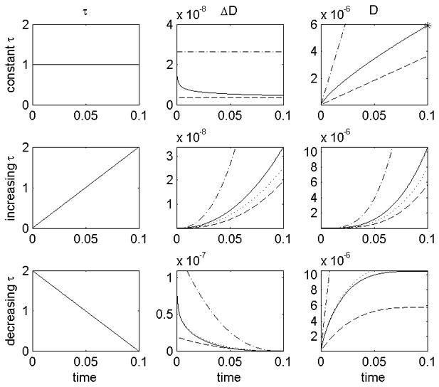
A comparison of infinitesimal damage (ΔD) and total damage (D) for different shear stress histories (top τ = constant, middle τ = increasing, bottom τ = decreasing). Damage models: mini power law (.-.-) 143, 145,55, 137, temporal derivative (…), Mitoh et al 139 and Yano et al 140 (- -), Grigioni et al (−) 146. Power law equation for total damage after constant shear stress (*). It can be seen that: both the temporal derivative and Grigioni’s equation predict the same total damage as the power law equation after a constant shear stress; but that using the temporal derivative, the infinitesimal damage at t=0.05 is the same for all three shear stress histories.
Arora et al 142, 141 developed a strain based model of haemolysis based on the knowledge that haemolysis is related to the straining of the RBC. They define a morphology tensor for the RBC which accounts for the shape change due to the shear rate, included are viscoelastic deformation, tank-treading motion of the membrane and the areal strain limit. They then calculate the strain along pathlines and this allows the calculation of the haemolysis.
The Lagrangian pathline approach has had some success in predicting haemolysis 139, 140, 141, however, obtaining pathlines has computational problems at near zero velocities and in recirculation regions, and does not necessarily take account of the entire flow field. Also, not all formulations take account of the damage history. The solution of a scalar transport equation has been suggested as a way to account for the whole Eulerian domain and, by appropriate selection of a source term, also include the damage history of the cells 149. Our group used this method to calculate haemolysis in the UltraMag pump 96.
7.2 Platelet Activation
Device induced platelet activation leads to blood clots and requires patients to take anti-coagulation medications which can in turn lead to bleeding. Minimising mechanical platelet activation would reduce the risk of clot formation and require lower doses of anti-coagulation medication. To this end it is important to understand the relationship between shear stress, exposure time and platelet activation. Platelet activation has been modelled assuming a haemolysis type power law equation 149, an infinitesimal damage based on Grigioni et al’s 146 haemolysis model 150 and using a transcendental equation 151:
| 10 |
where k is negative to give a positive first derivative and therefore ensure damage always accumulates.
In addition to shear stress platelets are activated by chemical agonists such adenosine diphosphate (ADP) and thrombin. This chemical activation should not be treated separately from shear activation, since agonist production by platelets is dependent on the activation state, and so functions as a positive feedback mechanism.
7.3 Thrombosis and Embolisation
Clotting within the device compromises its efficiency and can lead to device failure while embolization of clots from the device can cause neurological events and strokes, amongst other problems. Continuum models for platelet aggregation which include chemical activation have been formulated by Fogelson et al 152, 153, 154, 155, Sorensen et al 156, 157 and Goodman et al 158 and these models are fundamentally similar. A convection-diffusion-reaction equation is solved for each of the species involved: resting, and activated platelets, platelet released agonists (such as ADP), platelet synthesized agonists (such as thrombin and thromboxane A2), and prothrombin and antithrombin III which interact with thrombin. Platelet-platelet and platelet-surface adhesion are modelled via specified surface flux boundary conditions such that as the number of adhered platelets increases and the available free surface area decreases the probability of surface adhesion decreases. Surface activation can be included 156, 157, or alternatively shear activation of adhered cells may be modelled 158. Red blood cell enhanced platelet and large molecule diffusion can be incorporated either by specifying a diffusion constant, which is proportional to the wall shear rate 156, 157, or by allowing the diffusion constant to vary with the local shear stress 158.. The unknown parameters such as platelet adhesion rates and platelet diffusivity were found by fitting to experimental data from the literature or by performing experiments in straight tubes. Sorensen et al 157 tested their model by comparison with experimental results from the literature and platelet deposition was in good agreement with one anticoagulant (but not another). One of the main limitations of their model is that it does not account for mechanical interactions between the flow and the thrombus.
The model by Fogelson et al 152, 153, 154, 155 uses an elastic link function to describe the inter-platelet bonds and their evolution, and predicts a phase transition which can be interpreted as platelet aggregation. A forcing term ensures fluid flows around the formed thrombus, and the model can predict embolization. They used their model to show how clot development in atherosclerosis depends on plaque rupture site. Goodman et al 158 incorporate thrombus growth in their model using a simpler approach: when the volume of adhered platelets within a mesh element exceeds the volume of that element, the element becomes thrombus. The viscosity is increased 100,000 times, the boundary geometry is updated and the surface flux conditions are applied at the new boundary. Fluid forces on the growing thrombus are then tracked and the entire thrombus embolizes (and is removed from the grid) when the forces exceed a given characteristic adhesion strength. Their model was validated with experiments in constricted tubes. Video microscopy was used to measure formation, growth and embolization of thrombi, while scanning electron microscopy was used to measure adhered platelets. Good agreement was found for the location and quantity of adherent platelets, as well as for thrombus growth rates and embolization frequency.
Models featuring individual cells may capture the complex interactions involved in platelet aggregation. Fogelson’s micro scale approach 153 can model a collection of individual platelets and their interactions with the surrounding fluid, each other and the vessel walls. They use an immersed boundary method to simulate the passage of the Lagrangian platelet models through an Eulerian grid of the flow domain. Each platelet has a membrane with properties influencing the platelet’s deformation. Blyth and Pozrikidis 159 modelled a single platelet adhering to a surface using a boundary-element method with adhesion bond dynamics. Xu et al 160 have developed a thrombosis model which uses convection-diffusion-reaction equations for the biochemistry of the plasma with a discrete cellular Potts model of the thrombus involving platelets and RBCs.
Currently these cellular models are unsuitable for studying platelet activation and adhesion in real devices since they are computationally too demanding. There are a few examples of platelet activation models applied to medical devices 151 but none specifically applied to VADs. The complexity of the modelling required, combined with solving the three full dimensional flow in a VAD is a challenge yet to be solved.
8. Interaction with the Cardiovascular System
A VAD operates as part of the cardiovascular system and the two interact in numerous ways: from biochemical issues such as emboli induced by the device which go on to cause problems elsewhere in the body, to mechanical ones such as the flow and pressure within the device. These interactions complicate numerical modelling and have therefore only recently begun to be taken into account. Progress in this direction could lead to more accurate predictions of device performance in vivo, as well as predictions of the effect of the device on the body.
The mechanical interaction between a VAD and the native cardiovascular system is complicated: both the device and the failing native heart pump in parallel, the continuous flow from the device increases the steady flow component to the circulatory system, while the pulsatility of the flow from the native heart results in a pulsatile component in the flow through the mechanical device 161.
Usually flow simulations for continuous flow VADs are performed under steady flow conditions, and devices are optimized based on these steady flow results. However, it has been shown that the rate of change of flow rate influences the flow field. In particular, deceleration destabilizes the flow field promoting separation while acceleration stabilizes the flow 162. For a device operating with constant speed it might be logical to assume that the pressure head follows a single speed line from the H-Q curve, oscillating along the line as the flow rate changes during the cardiac cycle. However, this is not the case. The inertia of the blood results in hysteresis and therefore a closed loop in H-Q space 162, 50, 47. Some groups have looked at the effects of flow pulsatility 47, but since the calculations are far more computationally expensive, these studies are in the minority. A further obstacle to pulsatile flow calculations is to determine the inlet and outlet boundary conditions. In steady flow calculations the inlet boundary is usually set to a specific steady velocity profile and the outlet boundary is fixed at a uniform, steady pressure. The actual unsteady boundary conditions will be dependent on the nature of the flow from the native heart and the pressure in the aorta, both of which are the result of the interaction of the native cardiovascular system and the device.
While 3D CFD fluid-structure interaction (FSI) models of limited parts of the assisted vasculature are beginning to emerge 163, studying the effects of the device on the whole CV system, and vice versa, using 3D CFD would be an immense task and instead simpler models are used. For the vascular system electrical circuit analogue models (sometimes called lumped, or distributed, parameter models) have been developed. These models exploit an analogy between fluid flow through a compliant pipe network, and electrical circuits 164. The fluid flow, pressure and tube compliance correspond respectively to current, voltage and capacitance in the electrical circuit. The extent of the vasculature required depends on the use of the model: when investigating the device effects on the heart, most of the vasculature can be combined into a lumped parameter model. An alternative to circuit analogue models is to solve the 1D flow equations for a distributed, compliant network.
Most studies to date model the LV with a time varying elastance, E(t), to describe the pressure-volume, p-V, relationship in the LV 165:
| 11 |
The elastance curve is independent of cardiac load and only changes when the basic contractile function of the heart changes, for example due to drugs or disease, and normalization results in a general curve which is typical for a species. However, the time varying elastance has been found to change dramatically when the heart is assisted with a positive displacement pump due to extreme loading conditions which vary rapidly 166. There is also a change in the elastance with continuous flow rotary pumps: the end diastolic volume decreases and the maximum pressure increase 166 which is possibly due to damage to the heart tissue in the presence of the device. An alternative model is the one-fibre model which relates single sarcomere fibre stress and strain to ventricular pressure and volume using the ratio of cavity volume to wall volume 167. This model was extended by Cox et al 168 to include a baroreflex model.
Continuous flow rotary devices have a theoretical steady state pressure head given by 169, 170:
| 12 |
where H is Euler’s pressure head, u is the speed of the blade tips, Q is the flow through the pump, A is the effective discharge area and β is the blade angle at discharge. This is a quadratic function of speed and a linear function of flow. However, for the purpose of studying the system–device interaction the unsteady properties of the pump are essential. Including a term to account for flow acceleration, and also incorporating viscous effects, results in an equation for the pressure head of the following form 169, 171:
| 13 |
Combining the models of the heart, vasculature and VAD as described above results in a model of the whole assisted circulation. Such models have a variety of uses, for example: calculating the rotational speed required to both maintain adequate cardiac output and avoid left ventricular collapse 172, 173; calculating a time dependent speed such that the pump produces pulsatile flow 174; estimating the aortic pressure in the assisted circulation 175; and to study the effects of a failing blood pump with backflow on the left ventricle and aortic flow 171.
9. Blood Rheology
Blood is generally assumed to be a Newtonian fluid in VAD calculations, since shear rates found in blood pumps are generally high, and above 100 s−1 the viscosity of blood is constant. However, there are some reports that the shear thinning property effects pump characteristics at low rotational speeds and low flow rates. The pressure rise generated at low flow rate and low speeds is lower with the shear thinning fluid than with a Newtonian fluid 176, 177. The shear thinning viscous properties of blood have been modelled using the Casson, Carreau, power-law – shear models 178 and the visco-elastic properties 179 can be modelled with Maxwell type or Olroyd-B type models 180, 181. Use of these non-Newtonian models of blood rheology may lead to better predictions of the continuum properties of the flow in VADs.
Imaging of RBCs in the blade tip clearance region of a VAD showed that as the gap width was reduced the concentration of RBCs in the gap decreased, suggesting a mechanism whereby cells are excluded from the gap 182. Modelling this type of effect will require consideration of the blood rheology at the microscale, but is important from a blood damage perspective; if the cells are not flowing into the gap region then they are not being subjected to the high shear stresses found there.
10. Design Optimization
While CFD is often used to examine the flow fields in the pump, shear stresses on the casing or the blades, or to estimate blood damage parameters such as haemolysis, the question of how best to use this information remains. From a clinical perspective assessments of blood damage potential can be useful in choosing one pump over another for an individual patient, based on that patient’s systemic requirements and results for several different pumps. However, pump designers want to know how best to use the CFD results to improve the designs of their pumps. This is often done using a sophisticated trial and error approach. A designer examines the results and uses them, along with their own experience, to make a judgement on how best to improve the design. Often they will perform calculations on a range of designs before selecting one to continue with, or adapt further. Equations for designing specific pump components are available in the literature, for example discharge triangles or variation in pressure head with specific speed 170, and pump designs can be based on this information. However, it is often not clear how components will interact until they are tested. This testing can be done with CFD which accelerates the sophisticated trial and error process. There are numerous reports in the literature of these kinds of design improvement studies and just some of the ideas will be given here.
The impeller is one fundamental part of a pump but its optimum design is not necessarily intuitive since it has multiple parameters which affect the overall performance of a pump. CFD can be used for selecting the best design parameters. Arvand et al 183 calculated the flow through their mixed-flow pump with three impellers, differing in shape and presence of washout holes, and compared the following characteristics: pressure rise, efficiency, washout and leakage flow rates, torque and haemolysis. By ranking the impellers for each characteristic they could see which performed best in most categories. The impeller chosen gave the largest pressure rise, highest efficiency, lowest tip leakage flow and the lowest haemolysis, although this impeller performed only second best in terms of washout flow and torque. Curtas et al 48 found that blade curvature had a small effect on pump performance, with a straighter impeller creating a larger pressure head than evenly swept blades, but with a lower efficiency. Inlet and outlet angles both influenced the pump efficiency. Zhang et al 58 found flow recirculation in their newly designed axial flow pump and increased the blade expansion angle in increments from 0 to 20° until the recirculation was eliminated. Three different versions of the impeller for the Levitronix PediVAS 39 were simulated in order to assess the effects of longer blade tips on performance. The longer tips were found to increase the pressure head by around 50 %. In the Impella axial flow pump, Triep et al 61 investigated the effect of the length of the axial tip on the pump’s efficiency. Pumps with magnetically levitated impellers always have a narrow gap which separates the impeller from the pump housing. This gap is a secondary flow channel, and with high shear rates, and potentially long residence times, the region can be a blood damage hot spot. As such there have been many studies related to improving the parameters of the clearance gap. Anderson et al 44 studied flow in the clearance gap of the HeartQuest pump and showed that reducing the gap width from 0.76 to 0.25 mm increased the pump efficiency by reducing the flow through the clearance gaps. However, the shear rates necessarily increase which is undesirable. They highlight the presence of the Ekman layer, a thin layer adjacent to the rotating impeller casing, in which there is a force due to friction on the rotating surface of the impeller opposing the radial pressure gradient. The Ekman layer traps blood in the clearance gap increasing exposure to the high shear stress. Miyazoe et al 49 showed that reducing the clearance gap in the Nikkiso HPM-15 from 3.0 to 0.5 mm increased the shear stress 5 fold.
The above studies are examples of CFD based design improvement. A step above design improvement is CFD based design optimization 184. This requires coupling a CFD solver with a parameter optimization method 33 so that the flow field is solved for the initial design, and then, based on the values for efficiency, shear stress, recirculation or whatever the designers feel is important, the parameters for the pump are automatically adjusted. The flow field is then recalculated, if the results are improved, the changes are implemented, or if the results are still not good enough more changes will be automatically made. The whole process is iterative; only finishing when the design is optimized in terms of the specified objective performances. CFD based design optimization has been used in the development of, amongst others, axial flow pumps 184 and centrifugal pumps 60, as well a blood shearing instrument 185.
11. Validation
CFD is a powerful tool which has already reduced the time required to develop a new blood pump and has the potential to further increase development speed with the implementation of design optimization codes. Future development of blood damage models should enable simulation of haemolysis, platelet activation and thrombosis, thereby reducing the requirement for in vitro blood studies. However, it is easy to perform calculations but the variety of results which can be obtained with incorrect inputs is huge 186 and without confidence in the results CFD studies are of very limited value. Validation is the process of determining the degree to which a model is an accurate representation of the real world, and quantifies the uncertainty 23. A simulation is considered to be validated if the differences between its results and experimental data are small and if the uncertainties in the experimental results are also small 23.
Although extensive validation studies have been performed for industrial type pumps, these operate with different flow conditions and so the validation results do not necessarily provide useful information about CFD used in blood pumps. The different size, speeds, flow rates and working fluid mean that validation studies should be performed specifically for blood pumps. Validation is usually performed in vitro and most commonly uses the noninvasive optical techniques of flow visualization 74, 36, 187, 100, for qualitative information, and particle image velocimetry 43, 109, 46, 111, 59, 61, 62 or laser Doppler anemometry 188, 100 for quantitative measurements. Another noninvasive technique which can be used to measure the wall shear stress is oil drop streaking 110, 187. Hot film anemometry is an invasive technique which can also be used for studying in vitro flow and gives a high temporal resolution 189, 37, 103. Predictions of fluid forces can be validated by comparison with measurements of forces on the impeller 51, 52, 54, 11, 56. Many groups compare their CFD predictions of the pressure head produced by the pump with the measured values to give a bulk flow parameter for validation. While this does not show that flow field details are being correctly predicted, it does give some assurance and is a first step towards validation. Magnetic resonance imaging (MRI) has also been used to investigate the flow field in a pulsatile VAD 190, and as in vivo imaging tool MRI has the possibility of being used to look at VADs in vivo, although currently the majority of devices are not MRI compatible.
There have been a large number of comparisons of computational with experimental results for specific pumps, however, while acknowledging a few notable exceptions, including transient versus steady flow 47 and k-ε versus k-ω turbulence models 46, there is still a lack of published work on the differences due to different numerical methods.
12. Future Directions
From reviewing the current literature a number of trends become apparent for the future direction of research into VAD development using CFD.
12.1 Types of Pumps
One of the biggest limitations of VADs is their invasiveness, which makes them very uncomfortable, and their bulkiness, which prevents them being fitted in smaller patients. Smaller devices are currently being developed but some of these are only suitable for partial support. An area where CFD can be applied is the design and optimisation of less invasive pumps. Another area of VAD design which is ripe for development is pulsatile pumps. Compared to rotating pumps far less is known about flow calculations in pulsatile pumps and models of these could really aid understanding of their complicated flows.
12.2 Turbulence
While current simulations appear to predict pressure head curves to within 10 % of the experimental values, and the available PIV studies do show reasonable agreement, more work is needed to determine which turbulence models are the best to use in different devices. Flow through various devices should be calculated using all of the turbulence models available. From detailed comparisons of experimental and computational results the errors involved with using the different models could be determined and the best turbulence models for predicting flow in these types of devices should become clear. Newer turbulence models designed to simulate transition to turbulence, such as the k-kl-ω model 191 may yield more accurate predictions.
The amount of computing power available, mesh size and number of equations determines the length of time calculations take. Steady state calculations discussed in this article, of flow through whole VADs, take around 10 – 12 hours on single Pentium 3 850 MHz or 4 3.0 GHz processors 57, 138. A 2.83 GHz quad core with 32 GB memory can solve steady state turbulent flow for a mesh with 3 million elements in around 12 to 24 hours. The solution time for unsteady transient calculations is typically much longer, but depends on how many time steps are required. As computing power continues to increase Large Eddy Simulations, which have already been used for arterial blood flows, could be utilised. In the future Direct Numerical Simulation may be possible, at least for sections of the device or for validating the use of turbulence models.
12.3 Blood damage
The major obstacle in the path to increased patient use of VADs is blood damage. While haemolysis is no longer the largest blood damage issue, a universal model for haemolysis, which can be used in all devices, is still greatly desirable for evaluating pump designs. Thrombosis and emboli are currently major clinical challenges and the development of modelling approaches to predict these phenomena is vital. Current models for thrombosis consist of too many equations to implement in simulations of whole devices. However, if an approach can be found to apply their predictions to simulations the value of CFD to VAD development will be significantly increased. This will likely necessitate the use of multiscale approaches 192 which can model the nanoscopic molecular events in the context of the macroscopic device.
12.4 Cardiovascular system – Device Interaction
Interactions between the cardiovascular system and the VAD affect device performance and will likely influence the optimised pump design. Therefore models of devices should be incorporated into models of the whole cardiovascular system in order to more accurately predict flow in the device in vivo. The pulsatile nature of the flow can be studied and effects such as the destabilization, and possible turbulence generation, during flow deceleration could be investigated. In vivo conditions involve a lot of uncertainty since flow and pressure waves vary depending on exercise conditions and even beat to beat. Novel methods 193 could be used to account for these uncertain conditions in optimising the pump design. Combined models will also enable modelling of the effects of the device on the cardiovascular system, such as changes in pressure-flow waveforms, changes in local flow patterns and predictions of where emboli go.
12.5 Blood Rheology
Most current VAD calculations assume a Newtonian viscosity for blood. However, as calculations become more realistic so to should the models of blood rheology. Improved continuum models, as well as discrete models will be useful.
12.6 Validation
More validation studies are needed to build confidence in the use of CFD for VADs. In particular detailed visualization studies in a range of different devices should be performed and compared with the computational results. Establishing a database of experimental results which could act as test cases for groups wishing to validate their computational methods would be useful. In addition to optical imaging measurements of velocity, which are invaluable for assessing CFD predictions, measurements of blood damage characteristics are also required for validating blood damage models.
13. Conclusion
Cardiovascular disease, and heart failure specifically, are increasingly prevalent in today’s world and the improvement of treatments will help save lives. VADs are already in use clinically but have the potential to benefit many more patients if their current shortcomings can be eliminated. CFD is an invaluable tool in the development of VADs, enabling new designs to be tested rapidly and undesirable flow characteristics eliminated in successive versions before prototypes are manufactured. CFD is used for predicting pressure-flow characteristics and efficiency curves, revealing the detailed flow field to help eliminate regions of recirculation or stagnation and for calculating fluid dynamic forces. When combined with models of blood damage CFD has been used for predicting haemolysis and platelet activation by VADs. When combined with shape optimization algorithms it can be used in design optimization.
In summary, this article has discussed the current state of CFD applied to VADs and shown the variety of uses and benefits of calculations in terms of increasing the speed of device development. A number of areas for future research have also been identified.
Figure 2.

An axial flow VAD placed directly into the LV and inset showing the Jarvik 2000.
Figure 3.

A small axial VAD implanted through the aortic valve and insert showing the Impella.
Figure 4.

A positive displacement VAD placed extracorporeally and inset showing the Thoratec PVAD™.
Acknowledgments
This work was funded in part by National Institutes of Health (grant number: R01HL08810)
Appendix: Pump Characteristics
The following tables (Table 1, Table 2, and Table 3) report details of pumps from CFD studies in the literature. Maximum Reynolds numbers have been calculated based on the data given in the papers and using υ = μ/ρ, with μ=0.0035 kg m−1 s−1 and ρ=1050kg m−3, ω is the maximum rotational speed in rad s−1 and v is the mean velocity at the inlet calculated from the flow rate using v = Q/π(d/2)2 . For rotary pumps, both the maximum inlet Reynolds number, MaxRein, and the maximum Reynolds number for the impeller region, MaxReimp, have been calculated.
Footnotes
Publisher's Disclaimer: This is a PDF file of an unedited manuscript that has been accepted for publication. As a service to our customers we are providing this early version of the manuscript. The manuscript will undergo copyediting, typesetting, and review of the resulting proof before it is published in its final citable form. Please note that during the production process errors may be discovered which could affect the content, and all legal disclaimers that apply to the journal pertain.
References
- 1.WHO. Fact Sheet No. 317. [accessed 2009]. [Google Scholar]
- 2.Lloyd-Jones D, Adams RJ, Brown TM, Carnethon M, Dai S, et al. Heart Disease and Stroke Statisitics 2010 Update: A Report From the American Heart Association. Circulation. 2010;121:e46–e215. doi: 10.1161/CIRCULATIONAHA.109.192667. [DOI] [PubMed] [Google Scholar]
- 3.Warrell DA, Cox TM, Firth JD, Benz EJ. Oxford Textbook of Medicine. 4. Vol. 2 Oxford University Press; Oxford: 2005. [Google Scholar]
- 4.Health Resources and Services Administration, U.S. Department of Health and Human Services. Organ Procurement and Transplant Network. http://optn.transplant.hrsa.gov/latestData/rptData.asp.
- 5.Vega JD, Moore J, Murray S, Chend JM. Heart Transplantation in the United States, 1998–2007. American Journal of Transplantation. 2009;9:932–941. doi: 10.1111/j.1600-6143.2009.02568.x. [DOI] [PubMed] [Google Scholar]
- 6.Trost JC, Hillis LD. Intra-Aortic Balloon Counterpulsation. Am J Cardiol. 2006;97:1391–1398. doi: 10.1016/j.amjcard.2005.11.070. [DOI] [PubMed] [Google Scholar]
- 7.DiGiorgi PL, Rao V, Naka Y, Mehmet CO. Which Patient, Which Pump? J Heart Lung Transplant. 2003;22:221–235. doi: 10.1016/s1053-2498(02)00468-0. [DOI] [PubMed] [Google Scholar]
- 8.Mielck F, Quintel M. Extracorporeal Membrane Oxygenation. Current Opinion in Critical Care. 2005;11:87–93. doi: 10.1097/00075198-200502000-00014. [DOI] [PubMed] [Google Scholar]
- 9.Zhang T, Cheng G, Koert A, Zhang J, Gellman B, Yankey GK, Satput A, Dasse KA, Gilbert RJ, Griffith BP, Wu ZJ. Functional and Biocompatibility Performance of an Integrated Maglev Pump-Oxygenator. Artificial Organs. 2009;33:36–45. doi: 10.1111/j.1525-1594.2008.00672.x. [DOI] [PubMed] [Google Scholar]
- 10.Weiss WJ. Pulsatile Pediatric Ventricular Assist Devices. ASAIO Journal. 2005;51:540–545. doi: 10.1097/01.mat.0000178961.53220.da. [DOI] [PubMed] [Google Scholar]
- 11.Throckmorton AL, Lim DS, McCulloch MA, Jiang W, Song X, Allaire PE, Wood HG, Olsen DB. Computational Design and Experimental Performance Testing of an Axial-Flow Pediatric Ventricular Assist Device. ASAIO Journal. 2005;51:629–635. doi: 10.1097/01.mat.0000177541.53513.a8. [DOI] [PubMed] [Google Scholar]
- 12.Pauliks LB, Undar A. New Devices For Pediatric Mechanical Circulatory Support. Current Opinion in Cardiology. 2008;23:91–96. doi: 10.1097/HCO.0b013e3282f4cd9c. [DOI] [PubMed] [Google Scholar]
- 13.Song X, Throckmorton AL, Untaroiu A, Patel S, Allaire PE, Wood HG, Olsen DB. Axial Flow Blood Pumps. ASAIO Journal. 2003;49:355–364. [PubMed] [Google Scholar]
- 14.Hoshi H, Shinshi T, Takatani S. Third-generation Blood Pumps With Mechanical Noncontact Magnetic Bearings. Artificial Organs. 2006;30:324–338. doi: 10.1111/j.1525-1594.2006.00222.x. [DOI] [PubMed] [Google Scholar]
- 15.Thompson LO, Loebe M, Noon GP. What Price Support? Ventricular Assist Device Induced Systemic Response. ASAIO Journal. 2003;49:518–526. doi: 10.1097/01.mat.0000085672.42122.49. [DOI] [PubMed] [Google Scholar]
- 16.Genovese EA, Dew MA, Teuteberg JJ, Simon MA, Kay JSMP, Bhama JK, Bermudez CA, Lockard KL, Winowich S, Kormos RL. Incidence and Patterns of Adverse Event Onset During the First 60 Days after Ventricular Assist Device Implantation. Ann Thorac Surg. 2009;88:1162–1170. doi: 10.1016/j.athoracsur.2009.06.028. [DOI] [PMC free article] [PubMed] [Google Scholar]
- 17.Thoennissen NH, Schneider M, Allroggen A, Ritter M, Dittrcih R, Schmid C, Scheld HH, Ringelstein EB, Nabavi DG. High Level of Cerebral Microembolization in Patients Supported with the DeBakey Left Ventricular Assist Device. The Journal of Thoracic and Cardiovascular Surgery. 2005;130:1159–1166. doi: 10.1016/j.jtcvs.2005.02.068. [DOI] [PubMed] [Google Scholar]
- 18.Wilhelm MJ, Hammel D, Schmid C, Rhode A, Kaan T, Rothenburger M, Stypmann J, Schafers M, Schmidt C, Baba HA, Scheld HH. Long-term support in 9 patients with the DeBakey VAD for more than 200 days. The Journal of Thoracic and Cardiovascular Surgery. 2005;130:1122–1129. doi: 10.1016/j.jtcvs.2004.10.029. [DOI] [PubMed] [Google Scholar]
- 19.Schmid C, Jurmann M, Birnbaum D, Colombo T, Falk V, Feltrin G, et al. Influence of Inflow Cannula Length in Axial-flow Pumps on Neurologic Adverse Event Rate: Results From a Multi-center Analysis. Journal of Heart and Lung Transplant. 2008;27:253–260. doi: 10.1016/j.healun.2007.12.007. [DOI] [PubMed] [Google Scholar]
- 20.Schmid C, Welp H, Klotz S, Baba HA, Wilhelm MT, Scheld HH. Outcome of Patients Surviving to Heart Transplant After Being Mechanically Bridged for More Than 100 Days. The Journal of Heart and Lung Transplantation. 2003;22:1054–1058. doi: 10.1016/s1053-2498(02)01179-8. [DOI] [PubMed] [Google Scholar]
- 21.Gordon RJ, Quagliarello B, Lowy FD. Ventricular assist device-related infections. Lancet Infect Dis. 2006;6:426–437. doi: 10.1016/S1473-3099(06)70522-9. [DOI] [PubMed] [Google Scholar]
- 22.Dew MA, Kormos RL, Winowich S, Stanford EA, Carozza L, Borovetz HS, Griffith BP. Human Factors Issues in Ventricular Assist Device Recipients and Their Family Caregivers. ASAIO Journal. 2000;46:367–373. doi: 10.1097/00002480-200005000-00025. [DOI] [PubMed] [Google Scholar]
- 23.Versteeg HK, Malalasekera W. An Introduction to Computational Fluid Dynamics: The Finite Volume Method. 2. Pearson Education Limited; Harlow, UK: 2007. [Google Scholar]
- 24.Chang HS, Nakagawa H. Hypothesis on the Pathophysiology of Syringomyelia based on Simulation of Cerebrospinal Fluid Dynamics. J Neurol Neurosurg Psychiatry. 2003;74:344–347. doi: 10.1136/jnnp.74.3.344. [DOI] [PMC free article] [PubMed] [Google Scholar]
- 25.Doty RL, Cometto-Muniz JE, Jalowayski AA, Dalton P, Kendal-Reed M, Hodgson M. Assessment of Upper Respiratory Tract and Ocular Irritative Effects of Volatile Chemicals in Humans. Critical Reviews in Toxicology. 2004;34:85–142. doi: 10.1080/10408440490269586. [DOI] [PubMed] [Google Scholar]
- 26.Murakami S. Analysis and design of micro-climate around the human body with respiration by CFD. Indoor Air. 2004;14:144–156. doi: 10.1111/j.1600-0668.2004.00283.x. [DOI] [PubMed] [Google Scholar]
- 27.Taylor CA, Draney MT. Experimental and Computational Methods in Cardiovascular Fluid Mechanics. Annu Rev Fluid Mech. 2004;36:197–231. [Google Scholar]
- 28.Fraser KH, Meagher S, Blake JR, Easson WJ, Hoskins PR. Characterization of an Abdominal Aortic Velocity Wave in Patients with Abdominal Aortic Aneurysm. Ultrasound Med Biol. 2008;34:73–80. doi: 10.1016/j.ultrasmedbio.2007.06.015. [DOI] [PubMed] [Google Scholar]
- 29.Fraser KH, Li MX, Lee WT, Easson WJ, Hoskins PH. Fluid-structure interaction in axially symmetric models of abdominal aortic aneurysms. Proc IMechE Part H: J Engineering in Medicine. 2009;223:195–209. doi: 10.1243/09544119JEIM443. [DOI] [PubMed] [Google Scholar]
- 30.Fraser KH, Zhang T, Taskin ME, Griffith BP, Wu ZJ. Computational Fluid Dynamics Analysis of Thrombosis Potential in Ventricular Assist Device Drainage Cannulae. ASAIO J. 2010 doi: 10.1097/MAT.0b013e3181d861f1. [DOI] [PMC free article] [PubMed] [Google Scholar]
- 31.Sukumar R, Ahavale MM, Makhijani VB, Przekwas AJ. Application of Computational Fluid Dynamics Techniques to Blood Pumps. Artificial Organs. 1996;20:529–533. [PubMed] [Google Scholar]
- 32.Schima H, Muller MR, Papantonis D, Schlusche C, Huber L, Schmidt C, Trubel W, Thoma H, Losert U, Wolner E. Minimization of hemolysis in centrifugal blood pumps: influence of different geometries. Int J Artif Organs. 1993;16:521–529. [PubMed] [Google Scholar]
- 33.Antaki JF, Ghattas O, Burgreen GW, He B. Computational Flow Optimization of Rotary Blood Pump Components. Artificial Oragns. 1995;19:608–615. doi: 10.1111/j.1525-1594.1995.tb02389.x. [DOI] [PubMed] [Google Scholar]
- 34.Schima H, Tubel W, Wieselthaler G, Schmidt C, Muller MR, Siegl H, Losen U, Wolner E. The Vienna Implantable Centrifugal Blood Pump. Artifical Organs. 1994:18. doi: 10.1111/j.1525-1594.1994.tb03367.x. [DOI] [PubMed] [Google Scholar]
- 35.Pinotti M, Rosa ES. Computational Prediction of Hemolysis in a Centrifugal Ventricular Assist Device. Artificial Organs. 1995;19:267–273. doi: 10.1111/j.1525-1594.1995.tb02326.x. [DOI] [PubMed] [Google Scholar]
- 36.Burgreen GW, Loree HM, II, Bourque K, Dague C, Poirier VL, Farrar D, Hampton E, Wu ZJ, Gempp TM, Schob R. Computational Fluid Dynamics Analysis of a Maglav Centrifugal Left Ventricular Assist Device. Artificial Organs. 2004;28:874–880. doi: 10.1111/j.1525-1594.2004.07384.x. [DOI] [PubMed] [Google Scholar]
- 37.Chua LP, Song G, Yu SCM, Lim TM. Computational Fluid Dynamics of Gap Flow in a Biocentrifugal Blood Pump. Artificial Organs. 2005;29:620–628. doi: 10.1111/j.1525-1594.2005.29099.x. [DOI] [PubMed] [Google Scholar]
- 38.Chua LP, Song G, Lim TM, Zhou T. Numerical Analysis of the Inner Flow Field of a Biocentrifugal Blood Pump. Artificial Organs. 2006;30:467–477. doi: 10.1111/j.1525-1594.2006.00243.x. [DOI] [PubMed] [Google Scholar]
- 39.Zhang J, Koert A, Gellman B, Gempp TM, Dasse KA, Gilbert RJ, Griffith B, Wu ZJ. Optimization of a Miniature Maglev Ventricular Assist Device for Pediatric Circulatory Support. ASAIO Journal. 2007;53:23–31. doi: 10.1097/01.mat.0000247043.18115.f7. [DOI] [PubMed] [Google Scholar]
- 40.Zhu X, Zhang M, Zhang G, Liu H. Numerical Investigation on Hydrodynamics and Biocompatibility of a Magnetically Suspended Axial Blood Pump. ASAIO Journal. 2006;52:624–629. doi: 10.1097/01.mat.0000242161.50276.1e. [DOI] [PubMed] [Google Scholar]
- 41.Chua LP, Su B, Tau ML, Zhou T. Numerical Simulation of an Axial Blood Pump. Artificial Organs. 2007;31:560–570. doi: 10.1111/j.1525-1594.2007.00422.x. [DOI] [PubMed] [Google Scholar]
- 42.Kido K, Hoshi H, Watanabe N, Kataoka H, Ohuchi K, Asama J, Shinshi T, Yoshikawa M, Takatani S. Computational Fluid Dynamics Analysis of the Pediatric Tiny Centrifugal Blood Pump (TinyPump) Artificial Organs. 2006;30:392–399. doi: 10.1111/j.1525-1594.2006.00231.x. [DOI] [PubMed] [Google Scholar]
- 43.Day SW, McDaniel JC, Wood HG, Allaire PE, Landrot N, Curtas A. Particle Image Velocimetry Measurements of Blood Velocity in a Continuous Flow Ventricular Assist Device. ASAIO Journal. 2001;47:406–411. doi: 10.1097/00002480-200107000-00021. [DOI] [PubMed] [Google Scholar]
- 44.Anderson JB, Wood HG, Allaire PE, Bearnson G, Khanwilkar P. Computational Flow Study of the Continuous Flow Ventricular Assist Device, Prototype Number 3 Blood Pump. Artificial Organs. 2000;24:377–385. doi: 10.1046/j.1525-1594.2000.06442.x. [DOI] [PubMed] [Google Scholar]
- 45.Anderson JB, Wood HG, Allaire PE, McDaniel JC, Olsen DB, Bearnson G. Numerical Studies of Blood Shear and Washing in a Continuous Flow Ventricular Assist Device. ASAIO Journal. 2000;46:486–494. doi: 10.1097/00002480-200007000-00024. [DOI] [PubMed] [Google Scholar]
- 46.Song X, Wood HG, Day SW, Olsen DB. Studies of Turbulence Models in a Computational Fluid Dynamics Model of a Blood Pump. Artificial Organs. 2003;27:935–937. doi: 10.1046/j.1525-1594.2003.00025.x. [DOI] [PubMed] [Google Scholar]
- 47.Song X, Throckmorton AL, Wood HG, Allaire PE, Olsen DB. Transient and Quasi-Steady Computational Fluid Dynamics Study of a Left Ventricular Assist Device. ASAIO Journal. 2004;50:410–417. doi: 10.1097/01.mat.0000136507.57707.0f. [DOI] [PubMed] [Google Scholar]
- 48.Curtas AR, Wood HG, Allaire PE, McDaniel JC, Day SW, Olsen DB. Computational Fluid Dynamics Modeling of Impeller Designs for the HeartQuest Left Ventricular Assist Device. ASAIO Journal. 2002;48:552–561. doi: 10.1097/00002480-200209000-00019. [DOI] [PubMed] [Google Scholar]
- 49.Miyazoe Y, Sawairi T, Ito K, Konishi Y, Yamane T, Nishida M, Asztalos B, Masuzawa T, Tsukiya T, Endo S, Taenaka Y. Computational Fluid Dynamics Analysis to Establish the Design Process of a Centrifugal Blood Pump: Second Report. Artificial Organs. 1999;23:762–768. doi: 10.1046/j.1525-1594.1999.06418.x. [DOI] [PubMed] [Google Scholar]
- 50.Song X, Untaroiu A, Wood HG, Allaire PE, Throckmorton AL, Day SW, Olsen DB. Design and Transient Computational Fluid Dynamics Study of a Continuous Flow Ventricular Assist Device. ASAIO Journal. 2004;50:215–224. doi: 10.1097/01.mat.0000124954.69612.83. [DOI] [PubMed] [Google Scholar]
- 51.Untaroiu A, Wood HG, Allaire PE, Throckmorton AL, Day S, Patel SM, Ellman P, Tribble C, Olsen DB. Computational Design and Experimental Testing of a Novel Axial Flow LVAD. ASAIO Journal. 2005;51:702–710. doi: 10.1097/01.mat.0000186126.21106.27. [DOI] [PubMed] [Google Scholar]
- 52.Untaroiu A, Throckmorton AL, Patel SM, Wood HG, Allaire PE, Olse DB. Numerical and Experimental Analysis of an Axial Flow Left Ventricular Assist Device: The Influence of the Diffuser on Overall Pump Performance. Artificial Organs. 2005;29:581–591. doi: 10.1111/j.1525-1594.2005.29095.x. [DOI] [PubMed] [Google Scholar]
- 53.Throckmorton AL, Untaroiu A, Allaire PE, Wood HG, Matherne GP, Lim DS, Peeler BB, Olsen DB. Computational Analysis of an Axial Flow Pediatric Ventricular Assist Device. Artificial Organs. 2004;28:881–891. doi: 10.1111/j.1525-1594.2004.00009.x. [DOI] [PubMed] [Google Scholar]
- 54.Throckmorton AL, Untaroiu A, Allaire PE, Wood HG, Lim DS, McColloch MA, Olsen DB. Numerical Design and Experimental Hydraulic Testing of an Axial Flow Ventricular Assist Device for Infants and Children. ASAIO Journal. 2007;53:754–761. doi: 10.1097/MAT.0b013e31815581ea. [DOI] [PubMed] [Google Scholar]
- 55.Throckmorton AL, Untaroiu A. CFD Analysis of a Mag-Lev Ventricular Assist Device for Infants and Children: Fourth Generation Design. ASAIO Journal. 2008;54:423–431. doi: 10.1097/MAT.0b013e31817efaa8. [DOI] [PubMed] [Google Scholar]
- 56.Throckmorton AL, Untaroiu A, Lim DS, Wood HG, Allaire PE. Fluid Force Predictions and Experimental Measurements for a Magnetically Levitated Pediatric Ventricular Assist Device. Artificial Organs. 2007;31:359–368. doi: 10.1111/j.1525-1594.2007.00393.x. [DOI] [PubMed] [Google Scholar]
- 57.Zhang Y, Zhan Z, Gui XM, Sun HS, Zhang H, Zheng Z, Zhou JY, Zhu XD, Li GR, Hu SS, Jin DH. Design Optimization of an Axial Blood Pump With Computational Fluid Dynamics. ASAIO Journal. 2008;54:150–155. doi: 10.1097/MAT.0b013e318164137f. [DOI] [PubMed] [Google Scholar]
- 58.Zhang Y, Xue S, Gui XM, Sun HS, Hao Z, Zhu XD, Hu SS. A Novel Integrated Rotor of Axial Blood Flow Pump Designed With Computational Fluid Dynamics. Artificial Organs. 2007;31:580–585. doi: 10.1111/j.1525-1594.2007.00425.x. [DOI] [PubMed] [Google Scholar]
- 59.Apel J, Neudel F, Reul H. Computational Fluid Dynamics and Experimental Validation of a Microaxial Blood Pump. ASAIO Journal. 2001;47:552–558. doi: 10.1097/00002480-200109000-00031. [DOI] [PubMed] [Google Scholar]
- 60.Wu J, Antaki JF, Wagner WR, Snyder TA, Paden BE, Borovetz HS. Elimination of Adverse Leakage Flow in a Miniature Pediatric Centrifugal Blood Pump by Computational Fluid Dynamics-Based Design Optimization. ASAIO Journal. 2005;51:636–643. doi: 10.1097/01.mat.0000178966.79876.3d. [DOI] [PubMed] [Google Scholar]
- 61.Triep M, Brucker C, Schroeder W, Siess T. Computational Fluid Dynamics and Digital Particle Image Velocimetry Study of the Flow Through an Optimized Micro-axial Blood Pump. Artificial Organs. 2006;30:384–391. doi: 10.1111/j.1525-1594.2006.00230.x. [DOI] [PubMed] [Google Scholar]
- 62.Medvitz RB, Kreider JW, Manning KB, Fontaine AA, Deutsch S, Paterson EG. Development and Validation of a Computational Fluid Dynamics Methodology for Simulation of Pulsatile Left Ventricular Assist Devices. ASAIO Journal. 2007;53:122–131. doi: 10.1097/MAT.0b013e31802f37dd. [DOI] [PubMed] [Google Scholar]
- 63.Behr M, Arora DNY, Motomura T. Performance analysis of ventricular assist devices using finite element flow simulation. International Journal for Numerical Methods in Fluids. 2004;46:1201–1210. [Google Scholar]
- 64.Behr M, Arora D, Coronado OM. Models and finite element techniques for blood flow simulation. International Journal of Computational Fluid Dynamics. 2006;20:175–181. [Google Scholar]
- 65.Monaghan JJ. Smoothed Particle Hydrodynamics. Annual Review of Astronomy and Astrophysics. 1992;30:543–574. [Google Scholar]
- 66.De Frutos J, Novo J. A Spectral Element Method For The Navier-Stokes Equations With Improved Accuracy. SIAM Journal of Numerical Analysis. 2000;38:799–819. [Google Scholar]
- 67.Chen S, Doolen GD. Lattice Boltzmann Method For Fluid Flows. Annual Review of Fluid Mechanics. 1998;30:329–364. [Google Scholar]
- 68.Hosseini SM, Feng JJ. A particle-based model for the transport of erythrocytes in capillaries. Chemical Engineering Science. 2009;64:4488–4497. [Google Scholar]
- 69.Crowl LM, Fogelson AL. Computational Model of Whole Blood Exhibiting Lateral Platelet Motion Induced By Red Blood Cells. International Journal For Numerical Methods in Biomedical Engineering. 2010;26:471–487. doi: 10.1002/cnm.1274. [DOI] [PMC free article] [PubMed] [Google Scholar]
- 70.Shomura Y, Shimono T, Onoda K, Hioki I, Tenpaku H, Maze Y, Mizumoto T, Tani K, Tanaka K, Shimpo H, Yuasa H, Yada I. Clinical Experience with the Nikkiso Centrifugal Pump. Artif Organs. 1996;20:711–714. [PubMed] [Google Scholar]
- 71.Griffith K, Jenkins E, Pagani FD. First Americn Experience with the Terumo DuraHeart Left Ventricular Assist System. Perfusion. 2009;24:83–89. doi: 10.1177/0267659109106826. [DOI] [PubMed] [Google Scholar]
- 72.Mueller JP, Kuenzli A, Reuthebuch O, Dasse K, Kent S, Zuend G, Turina MI, Lachat ML. The CentriMag; A New Optimized Centrifugal Blod Pump with Levitating Impeller. The Heart Surgery Forum. 2004;7:e477–e480. doi: 10.1532/HSF98.20041068. [DOI] [PubMed] [Google Scholar]
- 73.De Robertis F, Birks EJ, Rogers P, Dreyfus G, Pepper JR, Khaghani A. Clinical Performance with the Levitronix Centrimag Short-term Ventricular Assist Device. J Heart Lung Transplantation. 2006;25:181–186. doi: 10.1016/j.healun.2005.08.019. [DOI] [PubMed] [Google Scholar]
- 74.Bearnson GB, Jacobs GB, Kirk J, Khanwilkar PS, Nelson KE, Long JW. HeartQuest Ventricular Assist Device Magnetically Levitated Centrifugal Blood Pump. Artificial Organs. 2006;30:339–346. doi: 10.1111/j.1525-1594.2006.00223.x. [DOI] [PubMed] [Google Scholar]
- 75.Maher TR, Butler KC, Poirier VL, Gearnes DB. HeartMate Left Ventricular Asssit Devices: A Generation of Implanted Blood Pumps. Artificial Organs. 2001;25:422–426. doi: 10.1046/j.1525-1594.2001.06756.x. [DOI] [PubMed] [Google Scholar]
- 76.Hijikate W, Shinshi T, Asama J, Li L, Hoshi H, Takatani S, Shimokohbe A. A Magnetically Levitated Centrifugal Blood Pump With A Simple-Structured Disposable Pump Head. Artif Organs. 2008;32:531–540. doi: 10.1111/j.1525-1594.2008.00576.x. [DOI] [PubMed] [Google Scholar]
- 77.Onuma H, Murakami M, Masuzawa T. Novel Maglev Pump With a Combined Magnetic Bearing. ASAIO Journal. 2005;51:50–55. doi: 10.1097/01.mat.0000151149.23519.19. [DOI] [PubMed] [Google Scholar]
- 78.Tuzun E, Harms K, Liu D, Dasse KA, Conger JL, Richardson JS, Fleischli A, Frazier OH, Radovancevic B. Preclinical Testing of the Levitronix Ultramag Pediatric Cardiac Assist Device in a Lamb Model. ASAIO Journal. 2007;53:392–396. doi: 10.1097/MAT.0b013e3180340974. [DOI] [PubMed] [Google Scholar]
- 79.Locke DH, Swanson ES, Walton JF, Willis JP, Heshmat H. Testing of a Centrifugal Blood Pump With a High Efficiency Hybrid Magnetic Bearing. ASAIO Journal. 2003;49:737–743. doi: 10.1097/01.mat.0000093963.64669.96. [DOI] [PubMed] [Google Scholar]
- 80.Frazier OH, Jacob LP. Small Pumps for Ventricular Assistance: Progress in Mechanical Circulatory Support. Cardiol Clin. 2007;25:553–564. doi: 10.1016/j.ccl.2007.09.001. [DOI] [PubMed] [Google Scholar]
- 81.Siess T, Nix C, Menzler F. From a Lab Type to a Product: A Retrospective View on Impella’s Assist Technology. Artif Organs. 2001;25:414–421. doi: 10.1046/j.1525-1594.2001.025005414.x. [DOI] [PubMed] [Google Scholar]
- 82.Noon GP, Moley D, Irwin S, Benkowski R. Development and Clinical Appplication of the MicroMed DeBakey VAD. Current Opinion in Cardiology. 2000;15:166–171. doi: 10.1097/00001573-200005000-00008. [DOI] [PubMed] [Google Scholar]
- 83.Griffith BP, Hardesty RL, Kormos RL, Trento A, Borovetz HS, Thompson ME, Bahnson HT. Temporary Use of the Jarvik-7 Artificial-Heart Before Transplantation. New England Journal of Medicine. 1987;316:130–134. doi: 10.1056/NEJM198701153160303. [DOI] [PubMed] [Google Scholar]
- 84.Frazier OH, Myers TJ, Gregoric ID, Khan T, Delgado R, Croitoru M, Miller K, Jarvik R, Westaby S. Initial Clinical Experience With The Jarvik 2000 Implantable Axial-Flow Left Ventricular Assist System. Circulation. 2002;105:2855–2860. doi: 10.1161/01.cir.0000018167.47314.af. [DOI] [PubMed] [Google Scholar]
- 85.Westaby S, Banning AP, Jarvik R, Frazier OH, Pigott DW, Jin WY, Catarino PA, Saito S, Robson D, Freeland A, Myers TJ, Poole-Wilson PA. First Permanent Implant of the Jarvik 2000 Heart. Lancet. 2000;356:900–903. doi: 10.1016/s0140-6736(00)02680-5. [DOI] [PubMed] [Google Scholar]
- 86.Burke DJ, Burke E, Parsaie F, Poirier V, Butler K, Thomas D, Taylor L, Maher T. The HeartMate II Design and Development of a Fully Sealed Axial Flow Left Ventricular Assist Device System. Artificial Organs. 2001;25:380–385. doi: 10.1046/j.1525-1594.2001.06770.x. [DOI] [PubMed] [Google Scholar]
- 87.Griffith BP, Kormos RL, Borovetz HS, Litwak K, Antaki JF, Poirier VL, Butler KC. HeartMate II Left Ventricular Assist System: From Concept To First Clinical Use. Ann Thorac Surg. 2001;71:116–120. doi: 10.1016/s0003-4975(00)02639-4. [DOI] [PubMed] [Google Scholar]
- 88.Kilic A, Nolan TDC, Li T, Yankey K, Prastein DJ, Cheng G, Jarvik R, Wu ZJ, Griffith BP. Early In Vivo Experience With The Pediatric Jarvik 2000 Heart. ASAIO Journal. 2007;53:374–378. doi: 10.1097/MAT.0b013e318038fc1f. [DOI] [PubMed] [Google Scholar]
- 89.Bertram CD, Qian Y, Reizes JA. Computational Fluid Dynamics Performance Prediction for the Hydrodynamic Bearings of the VentrAssist Rotary Blood Pump. Artif Organs. 2001;25:348–357. doi: 10.1046/j.1525-1594.2001.025005348.x. [DOI] [PubMed] [Google Scholar]
- 90.Hetzer R, Weng Y, Potapov EV, Pasic M, Drews T, Jurmann M, Hennig E, Muller J. First Experiences with a Novel Magnetically Suspended Axial Flow Left Ventricular Asssist Device. Eur J Cardiothorac Surg. 2004;25:964–970. doi: 10.1016/j.ejcts.2004.02.038. [DOI] [PubMed] [Google Scholar]
- 91.Undar A, Rosenberg G, Myers JL. Major Factors in the Controversy of Pulsatile Versus Nonpulsatile Flow During Acute and Chronic Cardiac Support. ASAIO Journal. 2005;51:173–175. doi: 10.1097/01.mat.0000161944.20233.40. [DOI] [PubMed] [Google Scholar]
- 92.Undar A. Myths and Truths of Pulsatile and Nonpulsatile Perfusion During Acute and Chronic Cardiac Support. Artificial Organs. 2004;28:439–443. doi: 10.1111/j.1525-1594.2004.00086.x. [DOI] [PubMed] [Google Scholar]
- 93.Deutsch S, Tarbell JM, Manning KB, Rosenberg G, Fontaine AA. Experimental Fluid Mechanics of Pulsatile Blood Pumps. Annual Review of Fluid Mechanics. 2006;38:65–86. [Google Scholar]
- 94.Roache PJ. Perspective: A method for uniform reporting of grid refinement studies. Journal of Fluids Engineering. 1994;116:405–413. [Google Scholar]
- 95.Roache PJ. Quantification of Uncertainty in Computational Fluid Dynamics. Annual Review of Fluid Mechanics. 1997;29:123–160. [Google Scholar]
- 96.Taskin ME, Zhang T, Gellman B, Fleischli A, Dasse KA, Griffith BP, Wu ZJ. Artificial Organs accepted for publication. Jan, 2011. Computational Characterization of Flow and Hemolytic Performance of the UltraMag Blood Pump for Circulatory Support. [DOI] [PubMed] [Google Scholar]
- 97.Panton RL. Incompressible Flow. John Wiley & Sons; New York: 1984. [Google Scholar]
- 98.Yamane T, Miyamoto Y, Tajima K, Yamazaki K. A Comparative Study Between Flow Visualization and Computational Fluid Dynamics Analysis for the Sun Medical Centrifugal Blood Pump. Artificial Organs. 2004;28:458–466. doi: 10.1111/j.1525-1594.2004.07161.x. [DOI] [PubMed] [Google Scholar]
- 99.Okamoto E, Hashimoto T, Inoue T, Mitamura Y. Blood Compatible Design of a Pulsatile Blood Pump Using Computational Fluid Dynamics and Computer-Aided Design and Manufacturing Technology. Artificial Organs. 2003;27:61–67. doi: 10.1046/j.1525-1594.2003.07183.x. [DOI] [PubMed] [Google Scholar]
- 100.Konig CS, Clark C, Mokhtarzadeh-Dehghan MR. Comparison of flow in numerical and physical models of a ventricular assist device using low- and high-viscosity fluids. Proc IMechE Part H: J Engineering in Medicine. 1999;213:423–432. doi: 10.1243/0954411991535031. [DOI] [PubMed] [Google Scholar]
- 101.Najarian S, Firouzi F, Fatouraee N, Dargahi J. Modeling and simulation of blood flow in a sac-type left ventricular assist device. Bio-Medical Materials and Engineering. 2007;17:229–233. [PubMed] [Google Scholar]
- 102.Fluent Inc. Fluent 63 User’s Guide. [Google Scholar]
- 103.Mizunuma H, Nakajima R. Experimental Study on the Shear Stress Distributions in a Centrifugal Blood Pump. Artificial Organs. 2007;31:550–559. doi: 10.1111/j.1525-1594.2007.00421.x. [DOI] [PubMed] [Google Scholar]
- 104.Wilcox DC. Turbulence Modeling for CFD. 3. DCW Industries; La Canada, CA: 2006. [Google Scholar]
- 105.White FM. Fluid Mechanics. McGraw-Hill Book Co; New York: 1979. [Google Scholar]
- 106.Smith WA, Allaire P, Antaki J, Butler KC, Kerkhoffs W, Kink T, Reul H. Collected Nondimensional Performance of Rotary Dynamic Blood Pumps. ASAIO Journal. 2004;50:25–32. doi: 10.1097/01.mat.0000104817.39941.9c. [DOI] [PubMed] [Google Scholar]
- 107.Wu J, Smith WA. Letter to the Editor: A Possible Major Mistake in the Paper Entitled “Collected Nondimensional Performance of Rotary Dynamic Blood Pumps”: Smith WA, Allaire P, Antaki J, Butler KC, Kerkoffs W, Kink T, Loree H, Reul H. ASAIO Journal 50:25–32, 2004. ASAIO Journal. 2007;53:255–256. doi: 10.1097/01.mat.0000104817.39941.9c. [DOI] [PubMed] [Google Scholar]
- 108.Zhang J, Gellman B, Koert A, Dasse KA, Gilbert RJ, Griffith BP, Wu ZJ. Computational and Experimental Evaluation of the Fluid Dynamics and Hemocompatability of the Centrimag Blood Pump. Artificial Organs. 2006;30:168–177. doi: 10.1111/j.1525-1594.2006.00203.x. [DOI] [PubMed] [Google Scholar]
- 109.Day SW, McDaniel JC, Wood HG, Allaire PE, Song X, Lemire PP, Miles SD. A Prototype HeartQuest Ventricular Assisit Device for Particle Image Velocimetry Measurements. Artificial Organs. 2002;26:1002–1005. doi: 10.1046/j.1525-1594.2002.07124.x. [DOI] [PubMed] [Google Scholar]
- 110.Lemire PP, McDaniel JC, Wood HG, Allaire PE, Landrot N, Song X, Day SW, Olsen D. The Application of Quantitative Oil Streaking to the HeartQuest Ventricular Assist Device. Artificial Organs. 2002;26:971–973. doi: 10.1046/j.1525-1594.2002.07114.x. [DOI] [PubMed] [Google Scholar]
- 111.Nishida M, Yamane T, Tsukamoto Y, Ito K, Konishi T, Masuzawa T, Tsukiya T, Endo S, Taenaka Y. Shear Evaluation by Quantitative Flow Visualization Near the Casing Surface of a Centrifugal Blood Pump. JSME International Journal. 2002;45:981–988. [Google Scholar]
- 112.Miyazoe Y, Sawairi T, Ito K, Konishi Y, Yamane T, Nishida M, Masuzawa T, Takiura K, Taenaka Y. Computational Fluid Dynamic Analyses to Establish Design Process of Centrifugal Blood Pumps. Artificial Organs. 1998;22:381–385. doi: 10.1046/j.1525-1594.1998.06169.x. [DOI] [PubMed] [Google Scholar]
- 113.Throckmorton AL, Untaroiu A, Allaire PE, Wood HG, Matherne GP, Lim DS, Peeler BB, Olsen DB. Computational Analysis of an Axial Flow Pediatric Ventricular Assist Device. Artificial Organs. 2004;28:881–891. doi: 10.1111/j.1525-1594.2004.00009.x. [DOI] [PubMed] [Google Scholar]
- 114.Wu J, Paden BE, Borovetz HS, Antaki JF. Computational FLuid Dynamics Analysis of Blade Tip Clearances on Hemodynamic Performance and Blood Damage in a Centrifugal Ventricular Assit Device. Artificial Organs. 2010;34:402–411. doi: 10.1111/j.1525-1594.2009.00875.x. [DOI] [PMC free article] [PubMed] [Google Scholar]
- 115.Bertram CD, Qian Y, Reizes JA. Computational Fluid Dynamics Performance Prediction for Hydrodynamic Bearings of the VentrAssist Rotary Blood Pump. Artificial Organs. 2001;25:348–357. doi: 10.1046/j.1525-1594.2001.025005348.x. [DOI] [PubMed] [Google Scholar]
- 116.Lahpor JR. State of the art: implantable ventricular assist devices. Current Opinion in Organ Transplantation. 2009;14:554–559. doi: 10.1097/MOT.0b013e3283303750. [DOI] [PubMed] [Google Scholar]
- 117.Siegenthaler MP, Martin J, van de Loo A, Doenst T, Bothe W, Beyersdorf F. Implantation of the Permanent Jarvik-2000 Left Ventricular Assist Device. J Am Coll Cardiol. 2002;39:1764–1772. doi: 10.1016/s0735-1097(02)01855-7. [DOI] [PubMed] [Google Scholar]
- 118.Heilmann C, Geisen U, Benk C, Berchtold-Herz M, Trummer G, Schlensak C, Zieger B, Beyersdorf F. Haemolysis in patients with ventricular assist devices: major differences between systems. Eur J Cardio Thor Surg. 2009;36:580–584. doi: 10.1016/j.ejcts.2009.04.015. [DOI] [PubMed] [Google Scholar]
- 119.Steinlechner B, Dworschak M, Birkenberg B, Duris M, Zeidler P, Fischer H, Milosevic L, Wieselthaler G, Wolner E, Quehenberger P, Jilma B. Platelet Dysfunction in Outpatients With Left Ventricular Assist Devices. Ann Thorac Surg. 2009;87:131–138. doi: 10.1016/j.athoracsur.2008.10.027. [DOI] [PubMed] [Google Scholar]
- 120.Radovancevic R, Matijevic N, Bracey AW, Radovancevic B, Elayda M, Gregoric ID, Frazier OH. Increased Leukocyte-Platelet Interactions During Circulatory Support With Left Ventricular Assist Devices. ASAIO Journal. 2009;55:459–464. doi: 10.1097/MAT.0b013e3181b235af. [DOI] [PubMed] [Google Scholar]
- 121.Snyder TA, Litwak KN, Tsukui H, Akimoto T, Kihara S, Yamazaki K, Wagner WR. Leukocyte-Platelet Aggregates and Monocyte Tissue Factor Expression in Bovines Implanted With Ventricular Assist Devices. Artificial Organs. 2007;31:126–131. doi: 10.1111/j.1525-1594.2007.00351.x. [DOI] [PubMed] [Google Scholar]
- 122.Leverett LB, Hellums JD, Alfrey CP, Lynch EC. Red Blood Cell Damage by Shear Stress. Biophysical Journal. 1972;12:257–272. doi: 10.1016/S0006-3495(72)86085-5. [DOI] [PMC free article] [PubMed] [Google Scholar]
- 123.Schmid-Schonbein H, Wells R. Fluid Drop-Like Transition of Erythrocytes under Shear. Science. 1969;165:288–291. doi: 10.1126/science.165.3890.288. [DOI] [PubMed] [Google Scholar]
- 124.Fischer TM. Tank-Tread Frequency of the Red Cell Membrane: Dependence on the Vicosity of the Suspending Medium. Biophysical Journal. 2007;93:2553–2561. doi: 10.1529/biophysj.107.104505. [DOI] [PMC free article] [PubMed] [Google Scholar]
- 125.Rand RP. The Red Cell Membrane II. Viscoelastic Breakdown of the Membrane. Biophysical J. 1964;4:303–316. doi: 10.1016/s0006-3495(64)86784-9. [DOI] [PMC free article] [PubMed] [Google Scholar]
- 126.Zhoa R, Antaki JF, Naik T, Bachman TN, Kameneva MV, Wu ZJ. Microscopic Investigation of Erythrocyte Deformation Dynamics. Biorheology. 2006;43:747–765. [PubMed] [Google Scholar]
- 127.Bronkhorst PJH, Streekstra GJ, Grimbergen J, Nijhof EJ, Sixma JJ, Brakenhoss GJ. A New Method to Study Shape Recovery of Red Blood Cells Using Multiple Optical Trapping. Biophys J. 1995;69:1666–1673. doi: 10.1016/S0006-3495(95)80084-6. [DOI] [PMC free article] [PubMed] [Google Scholar]
- 128.Sutera SP, Gardner RA, Boylan CW, Carroll GL, Chang KC, Marvel JS, Kil C, Gonen B, Williamson JR. Age-Related Changes in Deformability of Human Erythrocytes. Blood. 1985;2:275–282. [PubMed] [Google Scholar]
- 129.Stassen JM, Arnout J, Deckmyn H. The Hemostatic System. Current Medicinal Chemistry. 2004;11:2245–2260. doi: 10.2174/0929867043364603. [DOI] [PubMed] [Google Scholar]
- 130.Varga-Szabo D, Pleines I, Nieswandt B. Cell Adhesion Mechanisms in Platelets. Arteriosclerosis, Thrombosis and Vascular Biology. 2008;28:403–412. doi: 10.1161/ATVBAHA.107.150474. [DOI] [PubMed] [Google Scholar]
- 131.Wurzinger LJ, Opitz R, Wol M, Schmid-Schonbein H. Shear Induced Platelet Activation: A Critical Reappraisal. Biorheology. 1985;22:399–413. doi: 10.3233/bir-1985-22504. [DOI] [PubMed] [Google Scholar]
- 132.Hochareon P, Manning KB, Fontaine AA, Tarbell JM, Deutsch S. Correlation of In Vivo Clot Deposition With the Flow Characteristics in the 50 cc Penn State Artificial Heart: A Preliminary Study. ASAIO Journal. 2004;50:537–542. doi: 10.1097/01.mat.0000145694.40637.a0. [DOI] [PubMed] [Google Scholar]
- 133.Giersiepen M, Wurzinger LJ, Opitz R, Reul H. Estimation of shear stress-related blood damage in heart valve prosthesis-in vitro comparison of 25 aortic valves. International Journal of Artificial Organs. 1990;13:300–306. [PubMed] [Google Scholar]
- 134.Wurzinger LJ, Opitz R, Eckstein H. Mechanical Blood Trauma: An Overview. Angeiologie. 1986;38:81–97. [Google Scholar]
- 135.Paul R, Apel J, Klaus S, Schugner F, Schwindke P, Reul H. Shear Stress Related Blood Damage in Laminar Couette Flow. Artificial Organs. 2003;27:517–529. doi: 10.1046/j.1525-1594.2003.07103.x. [DOI] [PubMed] [Google Scholar]
- 136.Garon A, Farinas MI. Fast Three-Dimensional Numerical Hemolysis Approximation. Artificial Organs. 2004;28:1016–1025. doi: 10.1111/j.1525-1594.2004.00026.x. [DOI] [PubMed] [Google Scholar]
- 137.De Wachter D, Verdonck P. Numerical Calculation of Hemolysis Levels in Peripheral Hemodialysis Cannulas. Artificial Organs. 2002;26:576–582. doi: 10.1046/j.1525-1594.2002.07079.x. [DOI] [PubMed] [Google Scholar]
- 138.Arvand A, Hormes M, Reul H. A Validated Computational Fluid Dynamics Model To Estimate Hemolysis In A Rotary Blood Pump. Artificial Organs. 2005;29:531–540. doi: 10.1111/j.1525-1594.2005.29089.x. [DOI] [PubMed] [Google Scholar]
- 139.Mitoh A, Yano T, Sekine K, Mitamura Y, Okamato E, Kim DW, Yozu R, Kawada S. Computational Fluid Dynamics Analysis Of An Intra-Cardiac Axial Flow Pump. Artificial Organs. 2003;27:34–40. doi: 10.1046/j.1525-1594.2003.07190.x. [DOI] [PubMed] [Google Scholar]
- 140.Yano T, Sekine K, Mitoh A, Mitamura Y, Okamoto E, Kim DW, Nishimura I, Murabayashi S, Yozu R. An Estimation Method of Hemolysis Within An Axial Flow Blood Pump by Computational Fluid Dynamics Analysis. Artificial Organs. 2003;2003:920–925. doi: 10.1046/j.1525-1594.2003.00034.x. [DOI] [PubMed] [Google Scholar]
- 141.Arora D, Behr M, Pasquali M. Hemolysis Estimation In A Centrifugal Blood Pump Using A Tensor-based Measure. Artificial Organs. 2006;30:539–547. doi: 10.1111/j.1525-1594.2006.00256.x. [DOI] [PubMed] [Google Scholar]
- 142.Arora D, Behr M, Pasquali M. A Tensor-based Measure for Estimating Blood Damage. Artificial Organs. 2004;28:1002–1015. doi: 10.1111/j.1525-1594.2004.00072.x. [DOI] [PubMed] [Google Scholar]
- 143.Song X, Throckmorton AL, Wood HG, Antaki JF, Olsen DB. Computational Fluid Dynamics Prediction Of Blood Damage In a Centrifugal Pump. Artificial Organs. 2003;27:938–941. doi: 10.1046/j.1525-1594.2003.00026.x. [DOI] [PubMed] [Google Scholar]
- 144.Bludszuweit C. Model for a General Mechanical Blood Damage Prediction. Artificial Organs. 1995;19:583–598. doi: 10.1111/j.1525-1594.1995.tb02385.x. [DOI] [PubMed] [Google Scholar]
- 145.Chan K, Wong YW, Ding Y, Chua LP, Yu SCM. Investigation Of The Effect Of Blade Geometry on Blood Trauma in a Centrifugal Blood Pump. Artificial Organs. 2002;26:785–793. doi: 10.1046/j.1525-1594.2002.06954.x. [DOI] [PubMed] [Google Scholar]
- 146.Grigioni M, Morbiducci U, D’Avenio G, Di Benedetto G, Del Gaudio C. A Novel Formulation for blood trauma prediction by a modified power-law mathematical model. Biomechanical Modeling and Mechanobiology. 2005;4:249–260. doi: 10.1007/s10237-005-0005-y. [DOI] [PubMed] [Google Scholar]
- 147.Grigioni M, Daniele C, Morbiducci U, D’Avenio G, Di Benedetto G, Barbaro V. The Power-law Mathematical Model for Blood Damage Prediction: Analytical Developments and Physical Inconsistancies. Artificial Organs. 2004;28:467–475. doi: 10.1111/j.1525-1594.2004.00015.x. [DOI] [PubMed] [Google Scholar]
- 148.Goubergrits L, Affeld K. Numerical Estimation of Blood Damage in Artificial Organs. Artificial Organs. 2004;28:499–507. doi: 10.1111/j.1525-1594.2004.07265.x. [DOI] [PubMed] [Google Scholar]
- 149.Goubergrits L. Numerical modeling of blood damage: current status, challenges and future prospects. Expert Reviews on Medical Devices. 2006;3:527–531. doi: 10.1586/17434440.3.5.527. [DOI] [PubMed] [Google Scholar]
- 150.Nobili M, Sheriff J, Morbiducci U, Redaelli A, Bluestein D. Platelet Activation Due to Hemodynamic Shear Stresses: Damage Accumulation Model and Comparison to In Vitro Measurements. ASAIO Journal. 2008;54:64–72. doi: 10.1097/MAT.0b013e31815d6898. [DOI] [PMC free article] [PubMed] [Google Scholar]
- 151.Alemu Y, Bluestein D. Flow Induced Platelet Activation and Damage Accumulation in a Mechanical Heart Valve: Numerical Studies. Artificial Organs. 2007;31:677–688. doi: 10.1111/j.1525-1594.2007.00446.x. [DOI] [PubMed] [Google Scholar]
- 152.Fogelson AL. Continuum Models Of Platelet Aggregation: Formulation and Mechanical Properties. SIAM Journal on Applied Mathematics. 1992;52:1089–1110. [Google Scholar]
- 153.Fogelson A, Guy RD. Immersed-boundary-type models of intravascular platelet aggregation. Computer methods in applied mechanical engineering. 2008;197:2087–2104. [Google Scholar]
- 154.Fogelson AL, Tania N. Coagulation under Flow: The Influence of Flow-Mediated Transport on the Initiation and Inhibition of Coagulation. Pathophysiology of Haemostasis and Thrombosis. 2005;34:91–108. doi: 10.1159/000089930. [DOI] [PubMed] [Google Scholar]
- 155.Fogelson AL, Guy RD. Platelet-wall interaction in continuum models of platelet thrombosis: formulation and numerical solution. Mathematical Medicine and Biology. 2004;21:293–334. doi: 10.1093/imammb21.4.293. [DOI] [PubMed] [Google Scholar]
- 156.Sorensen EN, Burgreen GW, Wagner WR, Antaki JF. Computational Simulation of Platelet Deposition and Activation: I. Model Developement and Properties. Annals of Biomedical Engineering. 1999;27:436–448. doi: 10.1114/1.200. [DOI] [PubMed] [Google Scholar]
- 157.Sorensen EN, Burgreen GW, Wagner WR, Antaki JF. Computational Simulation of Platelet Deposition and Activation: II. Results for Poiseuille Flow over Collagen. Annals of Biomedical Engineering. 1999;27:449–458. doi: 10.1114/1.201. [DOI] [PubMed] [Google Scholar]
- 158.Goodman PD, Barlow ET, Crapo PM, Mohammed SF, Solen KA. Computational Model of Device-Induced Thrombosis and Thromboembolism. Annals of Biomedical Engineering. 2005;33:780–797. doi: 10.1007/s10439-005-2951-z. [DOI] [PubMed] [Google Scholar]
- 159.Blyth MG, Pozrikidis C. Adhesion of a blood platelet to injured tissue. Engineering Analysis with Boundary Elements. 2009 [Google Scholar]
- 160.Xu Z, Chen N, Kamocka MM, Rosen ED, Alber M. A multiscale model of thrombus development. J R Soc Interface. 2008;5:705–722. doi: 10.1098/rsif.2007.1202. [DOI] [PMC free article] [PubMed] [Google Scholar]
- 161.Stainback RF, Croitoru M, Hernandez A, Myers T, Wadia Y, Frazier OH. Echocardiographic Evaluation Of The Jarvik 2000 Axial-Flow LVAD. Tex Heart Inst J. 2005;32:263–270. [PMC free article] [PubMed] [Google Scholar]
- 162.Shu F, Vandenberghe S, Antaki JF. The Importance of dQ/dt on the Flow Field in a Turbodynamic Pump With Pulsatile Flow. Artificial Organs. 2009;33:757–762. doi: 10.1111/j.1525-1594.2009.00849.x. [DOI] [PMC free article] [PubMed] [Google Scholar]
- 163.Bazilevs Y, Gohean JR, Hughes TJR, Moser RD, Zhang Y. Patient-specifc isogeometric fluid-structure interaction analysis of thoracic aortic blood flw due to implantation of the Jarvik 2000 left ventricular assist device. Comput Methods Appl Mech Engrg. 2009;198:3534–3550. [Google Scholar]
- 164.Shim EB, Sah JY, Youn CH. Mathematical Modelling of Cardiovascular System Dynamics Using Lumped Parameter Method. Japenese Journal of Physiology. 2004;54:545–553. doi: 10.2170/jjphysiol.54.545. [DOI] [PubMed] [Google Scholar]
- 165.Suga H, Sagawa K. Instantaneous Pressure-Volume Relationships and Their Ratio in the Excised Supported Canine Left Ventricle. Circ Res. 1974;35:117–126. doi: 10.1161/01.res.35.1.117. [DOI] [PubMed] [Google Scholar]
- 166.Vandenberghe S, Segers P, Steendijk P, Meyns B, Dion RAE, Antaki JF, Verdonck P. Modeling Ventricular Function During Cardiac Assist: Does Time-Varying Elastance Work? ASAIO Journal. 2006;52:4–8. doi: 10.1097/01.mat.0000196525.56523.b8. [DOI] [PubMed] [Google Scholar]
- 167.Arts T, Bovendeerd PHM, Prinzen FW, Reneman RS. Relation between left ventricular cavity presure and volume and systolic fibre stress and strain in the wall. Biophys J. 1991;59:93–102. doi: 10.1016/S0006-3495(91)82201-9. [DOI] [PMC free article] [PubMed] [Google Scholar]
- 168.Cox LGE, Loerakker S, Rutten MCM, de Mol BAJM, van de Vosse FN. A Mathematical Model to Evaluate Control Strategies for Mechanical Circulatory Support. Artificial Organs. 2009;33:593–603. doi: 10.1111/j.1525-1594.2009.00755.x. [DOI] [PubMed] [Google Scholar]
- 169.Moscato F, Danieli GASH. Dynamic Modeling and Identification of an Axial Flow Ventricular Assist Device. Int J Artif Organs. 2009;32:336–343. doi: 10.1177/039139880903200604. [DOI] [PubMed] [Google Scholar]
- 170.Stepanoff AJ. Centrifugal and Axial Flow Pumps. Krieger Publishing Company; Malabar: 1957. [Google Scholar]
- 171.Vandenberghe S, Segers P, Meyns B, Verdonck PR. Effect of Rotary Blood Pump Failure on Left Ventricular Energetics Assessed by Mathematical Modeling. Artificial Organs. 2002;26:1032–1039. doi: 10.1046/j.1525-1594.2002.07105.x. [DOI] [PubMed] [Google Scholar]
- 172.Wu Y, Allaire P, Tao G, Olsen D. Modeling, Estimation and Control of Cardiovascular Systems with a Left Ventricular Assist Device. American Control Conference, Proceedings; 2005. pp. 3841–3846. [Google Scholar]
- 173.Wu Y. Adaptive Physiological Speed/Flow Control of Rotary Blood Pumps in Permanent Implantation Using Intrinsic Pump Parameters. ASAIO Journal. 2009;55:335–339. doi: 10.1097/MAT.0b013e3181aa2554. [DOI] [PubMed] [Google Scholar]
- 174.Hsu PL, Cheng SJ, Saumarez RC, Dawes WN, McMahon RA. An Extended Computational Model of the Circulatory System for Designing Ventricular Assist Devices. ASAIO Journal. 2008;54:594–599. doi: 10.1097/MAT.0b013e318185e1ce. [DOI] [PubMed] [Google Scholar]
- 175.Wu Y, Allaire P, Tao G, Olsen D. Study of Pressure Estimation for a Human Circulatory System with a LVAD. American Control Conference; 2006. p. 6. [Google Scholar]
- 176.Zhang G, Zhang M, Yang W, Zhu X, Hu Q. Effects of non-Newtonian fluid on centrifugal blood pump performance. International Communicationa in Heat and Mass Transfer. 2008;35:613–617. [Google Scholar]
- 177.Akamatsu T, Tsukiya T. Development of a Centrifugal Blood Pump with Magnetically Suspended Impeller and the Related Fluid Mechanical Problems. Indian Academy of Sciences. 1998;23:597–603. [Google Scholar]
- 178.Shibeshi SS, Collins WE. The Rheology of Blood Flow in a Branched Arterial System. Appl Rheo. 2005;15:398–405. doi: 10.1901/jaba.2005.15-398. [DOI] [PMC free article] [PubMed] [Google Scholar]
- 179.Thurston GB. Viscoelasticity of human blood. Biophys J. 1972;12:1205–1217. doi: 10.1016/S0006-3495(72)86156-3. [DOI] [PMC free article] [PubMed] [Google Scholar]
- 180.Anand M, Rajagopal KR. A Mathematical Model To Describe The Change In The Constitutive Character of Blood Due to Platelet Activation. C R Mecanique. 2002;330:557–562. [Google Scholar]
- 181.Yeleswarapu KK, Kameneva MV, Rajagopal KR, Antaki JF. The Flow of Blood In Tubes: Theory and Experiment. Mechanics Research Communications. 1998;25:257–262. [Google Scholar]
- 182.Antaki JF, Diao CG, Shu FJ, Wu JC, Zhao R, Kameneva MV. Microhaemodynamics within the blade tip clearance of a centrifugal turbodynamic blood pump. Proc IMechE Part H: J Engineering in Medicine. 2008;222:573–581. doi: 10.1243/09544119JEIM352. [DOI] [PubMed] [Google Scholar]
- 183.Arvand A, Hahn N, Hormes M, Akdis MMM, Reul H. Comparison of Hydraulic and Hemolytic Properties of Different Impeller Designs of an Implantable Rotary Blood Pump by Computational Fluid Dynamics. Artificial Organs. 2004;28:892–898. doi: 10.1111/j.1525-1594.2004.07379.x. [DOI] [PubMed] [Google Scholar]
- 184.Burgreen GW, Antaki JF, Wu ZJ, Holmes AJ. Computational Fluid Dynamics as a Development Tool for Rotary Blood Pumps. Artificial Organs. 2001;25:336–340. doi: 10.1046/j.1525-1594.2001.025005336.x. [DOI] [PubMed] [Google Scholar]
- 185.Wu J, Antaki JF, Snyder TA, Wagner WR, Borovetz HS, Paden BE. Design Optimization of Blood Shearing Instrument by Computational Fluid Dynamics. Artificial Organs. 2005;29:482–489. doi: 10.1111/j.1525-1594.2005.29082.x. [DOI] [PubMed] [Google Scholar]
- 186.Stewart SFC, Day S, Burgreen GW, Paterson EG, Manning KB, Hariharan P, Deutsch S, Giarra M, Cheek C, Reddy V, Berman MR, Myers MR, Malinauskas RA. Preliminary Results of FDA’s “Critical Path” Project to Validate Computational Fluid Dynamic Methods Used in Medical Device Evaluation. ASAIO J. 2009;55:173. [Google Scholar]
- 187.Wu ZJ, Gottlieb RK, Burgreen GW, Holmes JA, Borzelleca DC, Kameneva MV, Griffith BP, Antaki JF. Investigation of fluid dynamics within a miniature mixed flow blood pump. Experiments in Fluids. 2001;31:615–629. [Google Scholar]
- 188.Chua LP, Ong KS, Song G. Study of Velocity and Shear Stress Distributions in the Impeller Passages and the Volute of a Bio-centrifugal Ventricular Assist Device. Artificial Organs. 2008;32:376–387. doi: 10.1111/j.1525-1594.2008.00556.x. [DOI] [PubMed] [Google Scholar]
- 189.Chua LP, Ong KS, Yu CMS, Zhou T. Leakage Flow Rate and Wall Shear Stress Distributions in a Biocentrifugal Ventricular Assist Device. ASAIO Journal. 2004;50:530–536. doi: 10.1097/01.mat.0000144363.92963.cb. [DOI] [PubMed] [Google Scholar]
- 190.Markl M, Benk C, Klausmann D, Stalder A, Frydrychowicz A, Hennig J, Beyersdorf F. Three-dimensional magnetic resonance flow analysis in a ventricular assist device. J Thorac Cardiovasc Surg. 2007;134:1471–1476. doi: 10.1016/j.jtcvs.2007.05.024. [DOI] [PubMed] [Google Scholar]
- 191.Walters DK, Cokljat D. A Three-Equation Eddy-Viscosity Model for Reynolds-Averaged Navier-Stokes Simulations of Transitional Flows. Journal of Fluids Engineering. 2008;130:121401. [Google Scholar]
- 192.Yamaguchi T, Ishikawa T, Imai Y, Matsuki N, Xenos M, Deng Y, Bluestein D. Particle-Based Methods for Multiscale Modeling of Blood Flow in the Circulation and in Devices: Challenges and Future Directions. Annals of Biomedical Engineering. 2010;38:1225–1235. doi: 10.1007/s10439-010-9904-x. [DOI] [PMC free article] [PubMed] [Google Scholar]
- 193.Sankaran S, Audet C, Marsden AL. A method for stochastic constrained optimization using derivative-free surrogate pattern search and collocation. J Comp Phys. 2010;229:4664–4682. [Google Scholar]
- 194.Pitsis AA, Visouli AN, Ninios V, Bourgioukas G, Filippatos G, Kremastinos D, Burkhoff D, Long JW. Elective Bridging to Recovery After Repair: The Surgical Approach to Ventricular Reverse Remodeling. Artif Organs. 2008;32:730–735. doi: 10.1111/j.1525-1594.2008.00596.x. [DOI] [PubMed] [Google Scholar]
- 195.Farrar DJ, Bourque K, Dague CP, Cotter CJ, Poirier VL. Design Features, Developmental Status and Experimental Results With the HeartMate III Centrifugal Left Ventricular Assist System With a Magnetically Levitated Rotor. ASAIO Journal. 2007;53:310–315. doi: 10.1097/MAT.0b013e3180536694. [DOI] [PubMed] [Google Scholar]
- 196.Dasse KA, Gellman B, Kameneva MV, Woolley JR, Johnson CA, Gempp T, Marks JD, Kent S, Koert A, Richardson JS, Snyder TA, Wearden P, Wagner WR, Gilbert RJ. Assessment of Hydraulic Performance and Biocompatibility of a MagLev Centrifugal Pump System Designed for Pediatric Cardiac or Cardiopulmonary Support. ASAIO Journal. 2007;53:771–777. doi: 10.1097/MAT.0b013e31815dbf66. [DOI] [PMC free article] [PubMed] [Google Scholar]
- 197.Ugaki S, Ishino K, Osaki S, Kotani Y, Honjo O, Hoshi H, Yokoyama N, Ohuchi K, Takatani S, Sano S. Efficacy of a Miniature Centrifugal Rotary Pump (TinyPump) for Transfusion-Free Cardiopulmonary Bypass in Neonatal Piglets. ASAIO Journal. 2007;53:675–679. doi: 10.1097/MAT.0b013e3181590719. [DOI] [PubMed] [Google Scholar]
- 198.Nojiri C, Kijima T, Maekawa J, Horiuchi K, Kido T, Sugiyama T, Mori T, Sugiura N, Asada T, Umemura W, Ozaki T, Suzuki M, Akamatsu T, Westaby S. Development Status of Terumo Implantable Left Ventricular Assist System. Artificial Organs. 2001;25:411–413. doi: 10.1046/j.1525-1594.2001.025005411.x. [DOI] [PubMed] [Google Scholar]
- 199.Throckmorton AL, Untaroiu AAPE, Wood HG, Lim DS, McColloch MA, Olsen DB. Numerical Design and Experimental Hydraulic Testing of an Axial Flow Ventricular Assist Device for Infants and Children. ASAIO Journal. 2007;53:754–761. doi: 10.1097/MAT.0b013e31815581ea. [DOI] [PubMed] [Google Scholar]
- 200.Triep M, Brucker CSW, Siess T. Computational Fluid Dynamics and Digital Particle Image Velocimetry Study of the Flow Through an Optimized Micro-axial Blood Pump. Artificial Organs. 2006;30:384–391. doi: 10.1111/j.1525-1594.2006.00230.x. [DOI] [PubMed] [Google Scholar]