

Abstract
Purpose
The purpose of this study was to evaluate the clinical feasibility of a new method to orient three-dimensional (3D) computed tomography (CT) models to the natural head position (NHP). This method utilizes a small and inexpensive digital orientation device to record NHP in 3D. This device consists of a digital orientation sensor attached to the patient via a facebow and an individualized bite jig. The study was designed to answer two questions: 1) whether the weight of the new device can negatively influence the NHP; and 2) wether the new method is as accurate as the gold standard.
Materials and Methods
Fifteen patients with craniomaxillofacial deformities were included in the study. Each patient’s NHP is recorded 3 times. The 1st NHP was recorded using a laser scanning method without the presence of the digital orientation device. The 2nd NHP was recorded using the digital orientation device. Simultaneously, the 3rd NHP wa also recorded using the laser scanning method. Each recorded NHP measurement was then transferred to the patient’s 3D CT facial model, resulting in 3 different orientations for each patient. They include: the orientation generated using the laser scanning method without the presence of the digital orientation sensor and facebow (Orientation 1); the orientation generated using the laser scanning method with the presence of the digital orientation sensor and facebow (Orientation 2); and the orientation generated using the digital orientation device (Orientation 3). The comparisons are then made between Orientations 1 and 2, and Orientations 2 and 3, respectively. Statistical analyses are performed.
Results
The results show that in each pair, the delta between the 2 measurements is not statistically significantly different from 0 degrees. In addition, in the 1st pair, Bland and Altman’s lower and upper limits of the delta between the 2 measurements are within 1.5° in pitch and sub-degree in roll and yaw. In the 2nd pair, the limits of the delta in all three dimensions are within 0.5°.
Conclusion
Our technique can accurately record NHP in three dimensions and precisely transfer it to a 3D model. In addition, the extra weight of the digital orientation sensor and facebow has minimal influence on the self-balanced NHP establishment.
Keywords: Natural head position, self-balanced, three-dimensional, recording, transferring, computed tomography, computer modeling
Introduction
The natural head position (NHP) is the natural physiologic position of the head when a relaxed subject looks at an infinite horizon.1, 2 An accurately recorded NHP is vital for clinicians in the diagnosis and treatment of patients with craniomaxillofacial deformities. This is especially true for patients with significant facial asymmetries. Without the head orientated in NHP, the quantification of their deformities is often inaccurate.
As a result of recent advances in computer technology, three-dimensional (3D) computed tomography (CT) is now routinely used in clinical practice. However, since the orientation of the patient’s head is random during the CT acquisition, most 3D CTs are not oriented to the NHP. Unfortunately, traditional methods for recording NHP are limited to two-dimensional cephalograms3–8 and are not appropriate for 3D CT models. Because of this problem, clinicians have to place the 3D CT models in the NHP using 3D intracranial reference planes9 or their best perception9, 10.
In the past our group has utilized laser surface scans to orient 3DCT models in the NHP. We have found this technique to be very accurate11, 12 but it is impractical for routine clinical practice. These scans are acquired with the use of a calibrated laser scanner, which is very expensive and bulky. In order to solve this problem, the authors have developed a new method to orient a 3D CT model to the NHP. This method utilizes a small and inexpensive device to record NHP in 3D. The device consists of a digital orientation sensor attached to the patient via a bite jig and a facebow. The results from our previous in-vitro accuracy studies have demonstrated that our new method is highly accurate.13–16 However, the accuracy of this technique on patients has not yet been established. Moreover, although the total weight of the digital orientation sensor and the facebow is only 95g, the question of whether the weight of the new device can negatively influence the NHP has also not been answered. Therefore, we conducted this study to answer these questions.
Patients and Methods
Patients
A total of 15 consecutive patients with CMF deformities seen at our institution between July 2006 and July 2008 were included in the study. Patient inclusion criteria were: 1) Patients who were scheduled to undergo double-jaw orthognathic surgery to treat dentofacial deformities including hemifacial microsomia; 2) those who were scheduled to undergo a CT scan as a part of their treatment; and 3) patients who agreed to participate in the study. Patients with abnormal head postures (e.g. torticollis) were excluded because their self-balanced NHP is unreliable. The study was approved by Institutional Review Board and informed consent was obtained prior to the patient’s enrollment.
The patient sample size was calculated based on the study of Lundstrom et al which demonstrated that the reproducibility of NHP is close to 2°.17 Using the equivalence (simulation) for 2 correlated means method, the sample size was estimated with a correlation of 0.50 achieving 90% statistical power to detect equivalence when the margin of equivalence between our new technique and the laser surface scan method (gold standard) from −2.0 to 2.0 and the actual mean difference was 0.0. The calculation yielded 13 pairs. With a 10% of increase18, 15 pairs were used in this study. PASS statistical package (NCSS LLC, Kaysville, UT) was used for this calculation.
Laser Scanning Method to Orient a 3D CT into the NHP
Because of its proven accuracy,19, 20 this method can be considered to be the gold standard. It utilizes a calibrated laser surface scanner (Cyberware 3030 Head & Face Color Scanner, Cyberware Inc, Monterey, CA) to capture both the 3D geometry and the absolute orientation of the human face.19, 20 The patient sits on a calibrated chair positioned at the center of the laser scanner (Fig. 1a). He or she is asked to establish their NHP. The laser scanner then captures the surface geometry of the face and its absolute orientation, resulting in a 3D facial image in NHP (Fig. 1b). Using a 3DS software package (3D Studio Max, Autodesk, San Rafael, CA), the recorded NHP is transferred to the 3D CT facial model by registering it to the laser scanned facial image (Figs. 1c–1f).
Figure 1. Laser scanning method.
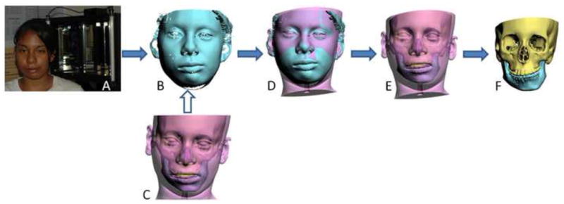
a. The patient sits on a calibrated chair that is positioned at the center of the laser scanner.
b. A 3D facial image in NHP is captured by the laser scanner.
c. A 3D CT facial and bone (underneath the soft tissue) model of the patient’s head
d. The recorded NHP is transferred to the 3D CT facial model by registering it to the 3D facial image in NHP.
e. The resulted 3D CT facial model in NHP
f. The resulted 3D CT bone model in NHP
New NHP Recording Method to Orient a 3D CT into the NHP
The new method tested in this study utilizes a novel device to record the NHP in 3D. The recording is then used to reorient the 3D CT in the NHP following a specific protocol. The new NHP recording device has three parts: a digital orientation sensor, a facebow and a bite-jig. The main component is the digital orientation sensor (Fig. 2a, 3DM, MicroStrain Inc, Williston, VT). The sensor is capable of digitally recording pitch, roll and yaw. It is coupled to the inferior aspect of the plastic facebow through a detachable connection. The specially designed facebow (Fig. 2b, Medical Modeling Inc, Golden, CO) contains an array of fiducial markers (Fig. 2c) that are compatible with CT and laser surface scanners. These fiducial markers are used to register individual 3D images. The inner aspect of the facebow contains a second detachable connector that links it to a bite jig. The bite jig consists of a stock frame and an individualized rigid bite registration.
Figure 2. NHP recording device assembly.
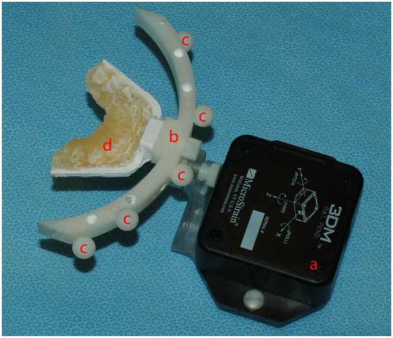
a. The digital orientation sensor
b. The facebow
c. The built-in fiducial markers
d. The individualized bite jig
In the first step of the new method, an individualized bite registration is obtained in centric relationship. The bite registration is taken using self-curing, rigid, dimensionally stable material, e.g. DuraLay (Reliance Dental Mfg. Co, Worth, IL) or DurLuxaBite (Chemisch-Pharmazeutische Fabrik GmbH, Germany). The material is placed on a stock frame and the impressions are taken on the occlusal surfaces of the upper and the lower teeth (Fig 2d).13–16 In the second step, the whole device is assembled and placed in the mouth (Fig 3a). The patient is then placed in the NHP and the pitch, roll and yaw readings of the orientation device are recorded (Fig 3b). In the third step, the orientation sensor is detached from the device and the patient is CT scanned with the bite jig and face bow in place. In the fourth step, the CT data is segmented creating 3D CT models of the skeleton (including teeth), the skin surface, and the fiducial markers (Fig 3c). In the fifth step, a computer model of our new device assembly, composed of the facebow and the orientation sensor, is imported into the computer (Fig 3d). To avoid confusion, from now on we will refer to this assembly as the CAD model. In the sixth step, the fiducial markers of the CAD model are registered to the fiducial markers of the 3D CT model (Fig 3e). This task is done automatically using the interactive closest point (ICP) algorithm21. Once this is done, the 3D CT models and the CAD model are linked together so any movement of the CAD model will produce the same movement in the 3D CT models. In the last step, the recorded pitch, roll and yaw are applied to the center of the CAD model’s orientation sensor, bringing the 3D CT model to the NHP (Fig 3f). Finally, the CAD model is hidden and a 3D CT is displayed in NHP (Fig 3g).
Figure 3. Digital Orientation Sensor Method.

a. The patient at the self-balanced NHP
b. The pitch, roll and yaw of the head orientation recorded by the digital orientation sensor
c. The patient’s 3D CT model of the head and the fiducial markers
d. A predetermined CAD model of the digital orientation sensor
e. The CAD model of the digital orientation sensor is registered and “glued” to the 3D CT model via the fiducial markers.
f. Applying the recorded pitch, roll and yaw to the center of the registered CAD model of the orientation sensor
g. The 3D CT model at the NHP is generated after the CAD model of the orientation sensor and fiducial markers are marked hidden.
Study Design
The study was designed to answer 2 questions: 1) whether the extra weight of the new device influenced the NHP, and 2) whether our method was as accurate as the gold standard. Each patient’s NHP was recorded 3 times. The NHP was established by asking the patients to self-balance their head to a position of comfort after flexing and extending the head. This was done with the patient sitting upright, looking at eye level straight at a blank wall 2 meters away. During this process, the examiners did not give any specific instructions that could potentially influence this position. The first NHP was recorded using the laser scanning method without the new NHP recording device in place (Fig 4). After the patient had rested for at least 15 minutes the new NHP recording device was inserted on the patient. The second and third NHPs were recorded simultaneously using both the laser scanner and the new NHP recording device (Fig 5).
Figure 4.
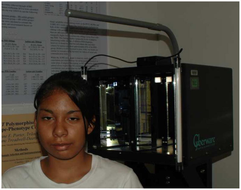
The 1st NHP is recorded using the laser scanning method when the digital orientation sensor, the bite jig and the facebow are not attached to the patient.
Figure 5.
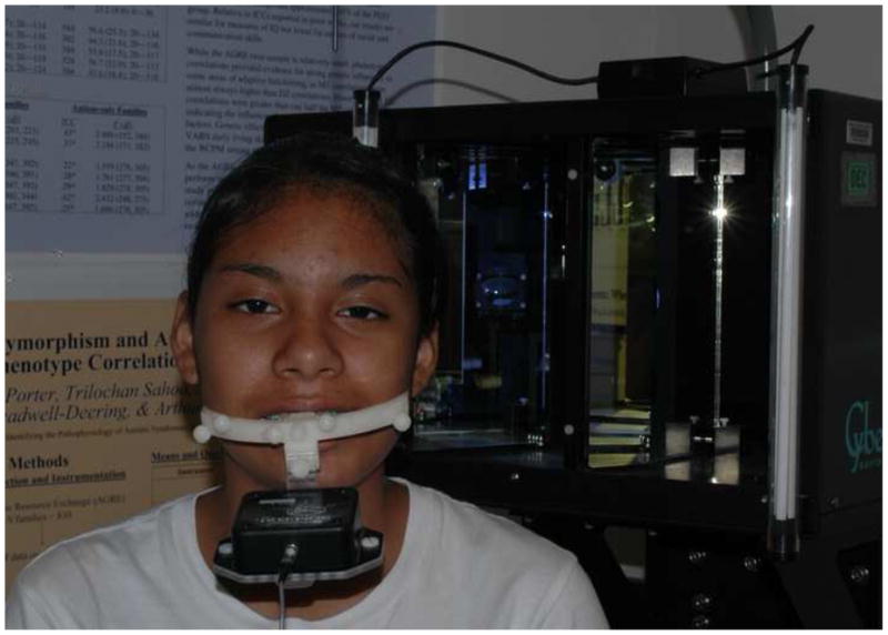
The 2nd and 3rd NHPs are simultaneously recorded with the digital orientation sensor and facebow attached to the patient.
Once the head orientation was recorded, the orientation sensor was detached from the facebow. A CT scan of the patient’s head was performed only with the bite jig and facebow in place. The CT was completed using the following scanning parameters: slice thickness of 1.25 mm and field of view of 22 cm. Finally, 3D CT models of the patient’s facial skin, skeleton and fiducial markers were generated. Three copies of these models were made and the 3 recorded NHPs were transferred to each of the 3D CT model copies (Fig 6). The same 3DS software package was utilized for this purpose.
Figure 6.
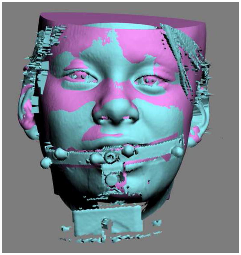
A 3D CT facial model is registered to the 3D facial image with the presence of the digital orientation sensor and facebow.
Data Analysis
After all the 3D CT facial models were oriented to the NHP, the pitch, roll, and yaw of each 3D CT facial model was automatically calculated and recorded using the 3DS software (Fig 7). For each patient, 3 sets of orientations of the 3D facial model were obtained: the orientation generated using the laser scanning method without the new NHP recording device (Orientation 1); the orientation generated using the laser scanning method with the presence of the new NHP recording device (Orientation 2); and the orientation generated using only the new NHP recording device (Orientation 3).
Figure 7.

The pitch, roll, and yaw of each 3D CT facial model are automatically calculated.
The clinical feasibility of the NHP recording method was evaluated using 2 separate tests (Fig 8). The first test was done to determine whether the extra weight of the digital orientation sensor and facebow influenced the patient’s NHP (Fig 8). This was done by comparing Orientation 1 (control group) to Orientation 2 (experimental group). The second test was done to determine whether the digital orientation device was equal to the current “gold standard” (Fig 8). This was done by comparing Orientation 2 (control group) to Orientation 3 (experimental group). For each comparison, the data was paired in pitch, roll, and yaw, respectively. The difference (delta) between each pair was calculated and tabulated. The resultant 3 tables were then screened and the largest delta in each patient, either in pitch, roll or yaw was selected to construct a 4th dimension. This 4th dimension represented a hypothetical largest delta between the 2 measurements in each patient.
Figure 8.

Flowchart of data analysis
The data was initially screened and the normal distribution assumption could not be rejected. Analysis of variance (ANOVA) for repeated measures was computed to test whether the delta between the 2 measurements was statistically apart from “0”, the hypothetical ideal number of the delta between 2 measurements. The response variable was the delta. The within factors were the 2 recordings and the 4 dimensions (pitch, roll, yaw and the constructed 4th dimension). NCSS statistics software package (NCSS Inc., Kaysville, UT) was used for this computation. In addition, a two-way mixed effect model (absolute agreement definition) for intraclass correlation coefficient was computed to determine the absolute agreement between the measurements in each pair. SPSS software package (SPSS Inc, Chicago, IL) was used for this computation. Finally, Bland and Altman’s methods22 were used to assess the agreement between the 2 measurements. Microsoft Excel (Microsoft Corp, Redmond, WA) was used for this computation. Based on published studies on reproducibility of establishing NHP, a difference of less than 2 degrees was considered to be not clinically significant.17, 23, 24
Results
To determine whether the extra weight of the digital orientation sensor and facebow influenced patient’s NHP establishment
ANOVA for repeated measures showed that the delta of the measurements recorded with and without the presence of the digital orientation sensor and the facebow was not statistically significantly different from 0 degrees [F(1,14)=0.12; P=0.74]. There was also no statistically significant difference in the delta among the 4 dimensions (pitch, roll, yaw, and the constructed 4th dimension) [F(3,42)=0.23; P=0.87]. In addition, the intraclass correlation coefficients between the 2 measurements were 0.997 (95% CI: 0.986, 0.999) in pitch, 0.996 (95% CI: 0.978, 0.999) in roll, and 0.987 (95% CI: 0.935, 0.997) in yaw, respectively. For the constructed 4th dimension of the hypothetical largest discrepancy between the 2 measurements, the coefficient was 0.996 (95% CI: 0.982, 0.999). All of the largest deltas came from the pitch measurements except one from the yaw. They indicated that the head orientations generated in the presence and absence of the digital orientation sensor and facebow were absolutely in agreement. Finally, using Bland and Altman’s methods for assessing measurement agreement, all the lower and upper limits of the delta between the 2 measurements were within 1.4° (Table 1).
Table 1.
Influence of the extra weight of the digital orientation sensor and the facebow on NHP establishment
| Mean | SD | Lower Limit of Difference (95% CI) | Upper Limit of Difference (95% CI) | Precision of Estimated Mean Differences of Agreement | |
|---|---|---|---|---|---|
| Pitch | −0.017 | 0.642 | −1.275 (−1.306, −1.245) | 1.241 (1.211, 1.271) | (−0.035, 0.000) |
| Roll | −0.022 | 0.189 | −0.393 (−0.430, −0.355) | 0.348 (0.311, 0.386) | (−0.044, −0.001) |
| Yaw | 0.014 | 0.379 | −0.729 (−0.754, −0.703) | 0.758 (0.732, 0.783) | (0.000, 0.029) |
| 4th Dimension | −0.104 | 0.668 | −1.412 (−1.591, −1.233) | 1.205 (1.026, 1.383) | (−0.207, 0.000) |
To determine whether the digital orientation sensor method was equal to the laser scanning method
ANOVA for repeated measures showed that the delta of the measurements recorded by the digital orientation sensor and the laser scanner methods was not statistically significantly different from 0 degrees [F(1,14)=0.00; P=0.98]. There was also no statistically significant difference in the delta among the 4 dimensions (pitch, roll, yaw, and the constructed 4th dimension) [F(3,42)=0.23; P=0.88]. In addition, the intraclass correlation coefficients were 1.000 (95% CI: 0.999, 1.000) in pitch, 0.998 (95% CI: 0.994, 0.999) in roll, and 0.997 (95% CI: 0.992, 0.999) in yaw, respectively. For the constructed 4th dimension of the hypothetical largest delta, the intraclass correlation coefficient was 0.999 (95% CI: 0.996, 1.000). The largest deltas in the constructed table were equally distributed among the pitch, roll and yaw measurements. They indicated that the head orientations generated by the 2 recording methods were absolutely in agreement. Finally, using Bland and Altman’s methods for assessing measurement agreement, all the lower and upper limits of the delta between the 2 recording methods were within 0.5° (Table 2).
Table 2.
The difference of the head orientations generated by the two methods
| Mean | SD | Lower Limit of Difference (95% CI) | Upper Limit of Difference (95% CI) | Precision of Estimated Mean Differences of Agreement | |
|---|---|---|---|---|---|
| Pitch | −0.01 | 0.109 | −0.225 (−0.235, −0.214) | 0.204 (0.194, 0.214) | (−0.016, −0.004) |
| Roll | −0.01 | 0.18 | −0.362 (−0.381, −0.344) | 0.341 (0.323, 0.360) | (−0.021, 0.000) |
| Yaw | −0.014 | 0.191 | −0.389 (−0.417, −0.362) | 0.361 (0.334, 0.389) | (−0.030, 0.002) |
| 4th Dimension | 0.033 | 0.211 | −0.380 (−0.426, −0.334) | 0.447 (0.400, 0.493) | (0.007, 0.060) |
Discussion
The most common method to orient a 3D CT model in NHP is to first visualize the 3D model in the computer and then to orient it to a balanced position based on the clinician’s best perception or digitized landmarks.25 This method may approximate the NHP if the craniofacial structures are perfectly symmetrical. However, when the upper face and skull base have significant asymmetries, this method is questionable. Another possible method is to simply record the NHP during CT scanning. However, this method is also questionable. If a medical spiral CT scanner is used, the patient is scanned in the supine position. Therefore, it is impossible to place the patient’s head in NHP during the CT scanning. If a CBCT scanner is used, the patient is in a sitting or standing position. Since the shortest scanning time is 5 seconds26, a chin rest is required to stabilize the patient’s head to ensure the quality of the CBCT images. While it is possible to position the patient’s head in NHP without the chin rest, the already-less-than-ideal quality of the CBCT images may be even more compromised due to the head motion. It is the authors’ opinion that a patient’s reference head orientation should be recorded directly on a patient, either at a self-balanced NHP or a doctor-manipulated head orientation. Clearly, there is a need for a technique that records the patient’s NHP and accurately transfers it to a 3D model.
Our Surgical Planning Laboratory has developed a new method to record the patient’s NHP and transfer it to the 3D CT model. Our method utilizes a small and inexpensive digital orientation sensor to record NHP in 3D. This sensor is attached to the patient via a facebow and an individualized bite jig. The results of this study confirm that the extra weight of the digital orientation sensor and facebow has minimal influence on the self-balanced NHP. The mean differences of the measurements recorded with and without the presence of the digital orientation sensor and the facebow are within a sub-degree in all three dimensions and the constructed 4th dimension. Bland and Altman’s measurement agreement assessment show that the lower and upper limits are within a sub-degree in roll and yaw, but within 1.3° in pitch and 1.4° degrees in the 4th dimension (mainly contributed from the pitch) after the facebow and the digital orientation sensor are attached. This may be due to fact that the weight of this device is located at the front of the face. However, we believe this deviation does not have clinical significance since the variability of NHP establishment is 2°.17, 23, 24
The results of this study also prove that new method is highly accurate. The mean differences of the measurements recorded using our method and the current gold standard are within a sub-degree in all three dimensions as well as the constructed 4th dimension. The accuracy is also verified by Bland and Altman’s methods for assessing measurement agreement. The largest lower and upper limit of the mean difference is within a sub-degree with a very tight 95% confidence interval, indicating the measurements are highly reliable.
An additional benefit of our new technique is that allows the detachment of the digital orientation sensor from the patient during CT scanning, thus preventing the artifacts from the circuit boards. Another benefit is that it is CBCT compatible. The field of view (FOV) in the CBCT scanner is much smaller than the regular medical spiral CT scanner. If the orientation sensor is attached to the facebow during the CBCT scan, the effective FOV for scanning the patient’s head is significantly reduced thus making CBCT useless. We have solved this problem by using a set of fiducial markers as the points of reference to register the CAD model of the digital orientation sensor to the patient’s 3D CT model. A final benefit of our technique is that the bite jig and facebow used for recording NHP are designed for multiple purposes, i.e. creating a composite skull model for computer-aided surgical simulation.11, 12, 27
Acknowledgments
The authors would like to thank Brendan Hi Lee, MD, PhD, Professor of Molecular and Human Genetics and Howard Hughes Medical Institute, Baylor College of Medicine, Houston, TX, for providing the Cyberware laser scanner.
This work was partially supported by NIH/NIDCR grant 1R41DE016171 and 2R42DE016171; and UCRC (UT-Houston Medical School) grant M01 RR002558 (NIH).
Footnotes
This manuscript was submitted in partial fulfillment of the requirements of the Degree of Master of Science at The University of Texas Houston Health Science Center (J.K.M.).
Publisher's Disclaimer: This is a PDF file of an unedited manuscript that has been accepted for publication. As a service to our customers we are providing this early version of the manuscript. The manuscript will undergo copyediting, typesetting, and review of the resulting proof before it is published in its final citable form. Please note that during the production process errors may be discovered which could affect the content, and all legal disclaimers that apply to the journal pertain.
References
- 1.Moorrees CF. Natural head position--a revival. Am J Orthod Dentofacial Orthop. 1994;105:512. doi: 10.1016/S0889-5406(94)70014-1. [DOI] [PubMed] [Google Scholar]
- 2.Moorrees CF, Kean MR. Natural head position, a basic consideration in the interpretation of cephalometric radiographs. Am J Phys Anthrop. 1958;16:213. [Google Scholar]
- 3.Cleall JF, Alexander WJ, McIntyre HM. Head posture and its relationship to deglutition. Angle Orthod. 1966;36:335. doi: 10.1043/0003-3219(1966)036<0335:HPAIRT>2.0.CO;2. [DOI] [PubMed] [Google Scholar]
- 4.Huggare JA. A natural head position technique for radiographic cephalometry. Dentomaxillofac Radiol. 1993;22:74. doi: 10.1259/dmfr.22.2.8375558. [DOI] [PubMed] [Google Scholar]
- 5.Showfety KJ, Vig PS, Matteson S. A simple method for taking natural-head-position cephalograms. Am J Orthod. 1983;83:495. [PubMed] [Google Scholar]
- 6.Usumez S, Orhan M. Inclinometer method for recording and transferring natural head position in cephalometrics. Am J Orthod Dentofacial Orthop. 2001;120:664. doi: 10.1067/mod.2001.117201. [DOI] [PubMed] [Google Scholar]
- 7.Usumez S, Orhan M. Reproducibility of natural head position measured with an inclinometer. Am J Orthod Dentofacial Orthop. 2003;123:451. doi: 10.1067/mod.2003.71. [DOI] [PubMed] [Google Scholar]
- 8.Vig PS, Showfety KJ, Phillips C. Experimental manipulation of head posture. Am J Orthod. 1980;77:258. doi: 10.1016/0002-9416(80)90081-0. [DOI] [PubMed] [Google Scholar]
- 9.Cevidanes L, Oliveira AE, Motta A, et al. Head orientation in CBCT-generated cephalograms. Angle Orthod. 2009;79:971. doi: 10.2319/090208-460.1. [DOI] [PMC free article] [PubMed] [Google Scholar]
- 10.Arnett GW, Gunson MJ. Facial planning for orthodontists and oral surgeons. Am J Orthod Dentofacial Orthop. 2004;126:290. doi: 10.1016/j.ajodo.2004.06.006. [DOI] [PubMed] [Google Scholar]
- 11.Gateno J, Xia JJ, Teichgraeber JF, et al. Clinical feasibility of computer-aided surgical simulation (CASS) in the treatment of complex cranio-maxillofacial deformities. J Oral Maxillofac Surg. 2007;65:728. doi: 10.1016/j.joms.2006.04.001. [DOI] [PubMed] [Google Scholar]
- 12.Xia JJ, Gateno J, Teichgraeber JF. New clinical protocol to evaluate craniomaxillofacial deformity and plan surgical correction. J Oral Maxillofac Surg. 2009;67:2093. doi: 10.1016/j.joms.2009.04.057. [DOI] [PMC free article] [PubMed] [Google Scholar]
- 13.Schatz EC, Xia JJ, Gateno J, et al. The development of a new technique of recording and transfering natural head position (NHP) in three dimensions. J Craniofac Surg. 2010;21 doi: 10.1097/SCS.0b013e3181ebcd0a. In press. [DOI] [PubMed] [Google Scholar]
- 14.Xia JJ, Gateno J, Schatz EC, et al. Accuracy of a new technique for recording natural head position in three dimensions. 90th Annual Meeting of American Association of Oral and Maxillofacial Surgeons; September 17–20, 2008; Seattle, WA. [Google Scholar]
- 15.Schatz EC. Department of Orthodontics. The University of Texas Health Science Center at Houston; Houston, TX: 2006. A new technique for recording natural head position in three dimensions (M.S. Thesis) [Google Scholar]
- 16.Weiskircher MN. Department of Orthodontics. The University of Texas Health Science Center at Houston; Houston, TX: 2007. Accuracy of a new technique for recording natural head position in three dimensions (M.S. Thesis) [Google Scholar]
- 17.Lundstrom F, Lundstrom A. Natural head position as a basis for cephalometric analysis. Am J Orthod Dentofacial Orthop. 1992;101:244. doi: 10.1016/0889-5406(92)70093-P. [DOI] [PubMed] [Google Scholar]
- 18.Chen YH, DeMets DL, Lan KK. Increasing the sample size when the unblinded interim result is promising. Stat Med. 2004;23:1023. doi: 10.1002/sim.1688. [DOI] [PubMed] [Google Scholar]
- 19.Bush K, Antonyshyn O. Three-dimensional facial anthropometry using a laser surface scanner: validation of the technique. Plast Reconstr Surg. 1996;98:226. doi: 10.1097/00006534-199608000-00004. [DOI] [PubMed] [Google Scholar]
- 20.Soncul M, Bamber MA. The reproducibility of the head position for a laser scan using a novel morphometric analysis for orthognathic surgery. Int J Oral Maxillofac Surg. 2000;29:86. [PubMed] [Google Scholar]
- 21.Besl PJ, McKay ND. A Method for Registration of 3-D Shapes. IEEE Trans on Pattern Analysis and Machine Intelligence. 1992;14:239. [Google Scholar]
- 22.Bland JM, Altman DG. Statistical methods for assessing agreement between two methods of clinical measurement. Lancet. 1986;1:307. [PubMed] [Google Scholar]
- 23.Bjerin R. A comparison between the Frankfort horizontal and the sella turcica–nasion as reference planes in cephalometric analysis. Acta Odontol Scand. 1957;15:1. [Google Scholar]
- 24.Moorees CF. Natural head position, a basic consideration in the interpretation of cephalometric radiographs. Am J Phys Anthrop. 1958;16:213. [Google Scholar]
- 25.Swennen GR, Schutyser F, Barth EL, et al. A new method of 3-D cephalometry Part I: the anatomic Cartesian 3-D reference system. J Craniofac Surg. 2006;17:314. doi: 10.1097/00001665-200603000-00019. [DOI] [PubMed] [Google Scholar]
- 26.Next generation i-CAT specifications. [Accessed on Feb 26, 2009]; Available at http://www.imagingsciences.com/pro_iCAT_NextGen_specs.htm.
- 27.Xia JJ, Gateno J, Teichgraeber JF. Three-dimensional computer-aided surgical simulation for maxillofacial surgery. Atlas Oral Maxillofac Surg Clin North Am. 2005;13:25. doi: 10.1016/j.cxom.2004.10.004. [DOI] [PubMed] [Google Scholar]