Abstract
Patients with long-wire medical implants are currently prevented from undergoing MRI scans due to the risk of RF heating. We have developed a simple technique for determining the heating potential for these implants using reversed RF polarization. This technique could be used on a patient-to-patient basis as a part of the standard pre-scan procedure to ensure that the subject’s device does not pose a heating risk. By using reversed quadrature polarization, the MR scan can be sensitized exclusively to the potentially dangerous currents in the device. Here, we derive the physical principles governing the technique and explore the primary sources of inaccuracy. These principles are verified through finite-difference simulations and through phantom scans of implant leads. These studies demonstrate the potential of the technique for sensitively detecting potentially dangerous coupling conditions before they can do harm.
Keywords: reversed RF polarization, implant safety, pacemakers and MRI, quadrature reversal
Introduction
Millions of people with long-wire implants such as cardiac pacemakers, ICDs, and neurostimulators are prevented from undergoing MRI because of potential interactions between their implant and the various fields used for imaging (1, 2). Some of the risks arising from these interactions can be addressed through MR-aware implant design. For example, MR-induced pacemaker malfunctions have been successfully managed for non-pacemaker-dependent patients by the provision of an ‘MRI mode’ to disable the device while in the MR suite (3, 4).
However, the risk of RF heating, wherein dangerous currents are induced into the implant’s wire lead through inductive and/or capacitive coupling with the transmitted B1 field (5), has proven difficult to eliminate through clever device design. These B1 field interactions are particularly problematic because many implants require an extended conductor in order to efficiently perform their primary function, and the mere presence of this conductor is sufficient to create unsafe heating under certain circumstances. Continuing research into coiled leads (6), distributed RF traps (7), flexible transformers (8), and other wire modifications may reduce the likelihood of such conditions arising, but design changes alone are unlikely to completely eliminate risk. Even if a theoretical anti-coupling device could entirely eliminate RF coupling when working properly, it could malfunction and thereby silently expose the patient to significant danger.
A potential solution involves calculating a ‘safety index’ to estimate the maximum theoretical heating potential for a device (9). However, this approach conservatively determines the worst-case coupled power for a given device without taking into account the specific device configuration within the patient and magnet at the time of scanning. Such techniques thus would prohibit the use of a wide range of MR scans that could have been conducted safely.
Despite the unresolved potential for RF heating, patients with long-wire implants do receive MRI scans. Several studies of pacemaker and ICD patients have reported no adverse effects for small cohorts of patients scanned with their devices disabled and under strict imaging limitations (4, 10–12). However, two recent incidents of brain injury (13, 14) occurred in patients with implanted deep-brain stimulators who were scanned with protocols that deviated from the manufacturers’ recommendations. These studies demonstrate the variability of risk that arises from the different lead lengths, placements, coiling strategies, and imaging parameters in routine clinical use. As more and more patients with implants are scanned, it is important to have easy and reliable methods for stratifying risk.
The same wire currents that cause implant heating also produce a B1 field near the wire, resulting in local RF enhancement or cancellation in MR images (15, 16). This phenomenon has been exploited for catheter visualization, wherein a resonant coil is intentionally coupled to the RF receiver to enhance its signal (17,18). These signal deviations are detectable even when the coupled power is too low to cause dangerous heating, and thus could be safely detected by conducting a preliminary MR scan of sufficiently low RF power. Previous work from our research group (19, 20) has demonstrated the potential for detecting and modeling wire currents from a series of MR images along the axis of the wire. Unfortunately, this technique requires a high-resolution volumetric scan followed by fitting data to a nonlinear model. Such a procedure would not be ideal for use as a fast pre-scan to stratify risk.
Here, we propose a new technique by which a device’s coupling can be rapidly quantified by an MR pre-scan that reverses the direction of RF polarization in the quadrature transmit/receive chain. When the transmitter polarization is perfectly reversed, MR excitation does not occur. Similarly, perfect reversal of the receiver polarization makes it insensitive to precessing MR spins. However, the presence of a coupled implant within the coil volume creates a secondary RF field that is not reverse-polarized, and therefore creates MR signal. Thus, a reverse-polarized image of a patient with a potentially dangerous implant should contain signal only in regions where coupling is present. Furthermore, the magnitude of the received signal is related to the degree of coupling. Data from a single projection image could then be used either to approximate the wire current and set RF operating limits, or to simply provide a ‘go or no-go’ directive to the operator.
In this work, we present a theoretical analysis for RF polarization reversal and investigate the electromagnetic factors that determine its effectiveness. These factors are then demonstrated through simplified full-wave simulations. Two experimental implementations are discussed, and phantom and in vivo studies are shown that demonstrate the reversed-polarization concept.
Theory
Spin magnetization M in a magnetic field B0 precesses due to the aligning force described by the differential Bloch equation:
| (1) |
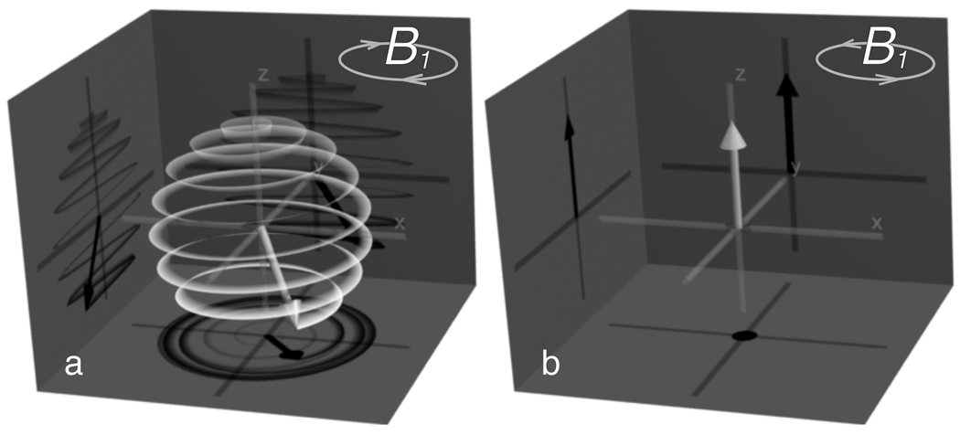
For hydrogen spins with positive gyromagnetic ratio γ, this relationship dictates that precession occurs about B0 with negative angular velocity ω = − γB0 (as shown in Fig. 1a). Such a rotation is considered ‘left-handed’, and therefore we will denote fields rotating in this direction by the subscript L. Conversely, fields with positive angular velocity (‘right-handed’ fields) will receive the subscript R.
Figure 1.
Effect of B1 polarity on excitation. A left circularly polarized B1 field (a) produces resonant excitation, while a right circularly polarized field (b) has no effect on magnetization. The white vector represents net magnetization, and the white line traces its path over time. The main B0 field is directed along the positive z axis.
Because precession is left-handed, spins are optimally excited with a left circularly polarized magnetic field, BL:
| (2) |
where BL = (Bx − jBy)/2 is the complex phasor (|BL|ejϕ) of the rotating excitation field, and ax and ay represent unit vectors in the transverse directions. Note that this definition follows the formalism of the electromagnetics literature (21, 22), where the time-domain transverse field is defined as:
In this notation, the left-handed rotation of the field is more readily apparent.
If a right circularly polarized RF field BR is instead used,
| (3) |
where BR = (Bx + jBy)/2, then resonant excitation does not occur (Fig. 1b) and no MR signal would be generated. Because of this difference in signal-generating ability, this right-polarized transmit field can also be considered ‘reverse’ polarized.
Reversed Receiver Sensitivity
To this point, we have only considered the transmit field responsible for excitation, but a similar analysis can be applied to received RF signals. MR signals are optimally received by an RF receiver coil phased to generate a right-hand circularly polarized impulse response. This is easily proven by application of the Lorentz reciprocity principle (23, 24) and elliptic polarization analysis (21). Briefly, a left-hand precessing magnetization M(ax + jay) has nonzero dot-product (reaction) with BR and zero dot-product with BL. Hence, a receiver tuned to BR has maximum detection sensitivity. Reversing the polarization of the receiver coil; i.e., making it sensitive to BL only, results in zero received signal.
Thus, the polarization of a quadrature RF coil can be reversed independently for excitation and reception through the appropriate selection of BR and BL. Reversing the transmitted RF polarity results in no excitation, while reversing the receiver’s polarity results in a lack of sensitivity to MR signals.
Quadrature Coil Polarization Switching
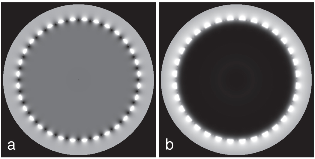
Birdcage coils are designed to create a spatially uniform, circularly polarized transverse RF field when excited at physical ports 90° apart with correct amplitude and phasing (25). Fig. 2 shows excitations under ideal conditions for a 32-rung birdcage when phased for either forward or reversed polarization.
Figure 2.
Ideal 32-rung birdcage excitation. A forward-polarized birdcage (a) produces a uniformly large excitation over its central volume. When reverse polarized (b), the excitation becomes uniformly zero over the same volume.
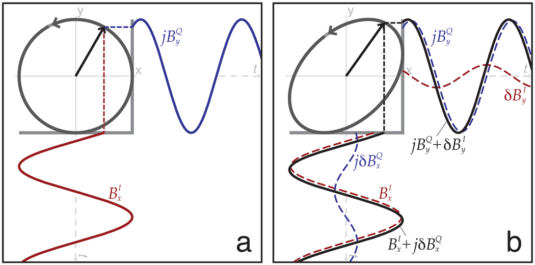
To analyze the effects of imperfect quadrature excitation, we consider two ports: an I port creating a desired field and a residual field, and a Q port creating a desired field and a residual field. Figure 3 illustrates how these fields combine to produce reversed transmitter polarization. If the Q port is phased to lead I by 90° (I+jQ), we generate the forward transmit and reversed receive effective fields of:
| (4) |
| (5) |
Figure 3.
Effect of quadrature imperfection. A perfectly reverse-polarized excitation (a) creates right circularly polarized magnetization from orthogonal components . When quadrature imperfections are present (b), elliptical polarization results.
If we switch the sign of the Q port to lag I by 90° (I-jQ), reversed transmit and forward receive fields result:
| (6) |
| (7) |
In the ideal case, the residual fields are zero and the port amplitudes are equal . As a result, the reverse modes cancel to zero for both transmit and receive. Deviations from these ideal conditions may occur for three reasons. First, any imbalance in instrumentation that creates an amplitude or phase deviation from quadrature in the I and Q channels will lead to incomplete suppression of the undesired rotating field term. Second, the intrinsic source field homogeneity degrades near coil conductors. Finally, even if the hardware excites perfectly phased, balanced and uniform source fields, a conductive object loading the coil can result in unequal scattered fields for each source component.
Electric Field Polarization Switching
For RF safety assessment, it is important that the reversal of RF polarization have a known effect on the electric fields induced in the sample, which are directly responsible for the coupled current and potential device heating. Consider for example the z-directed electric fields, , which arise from independent excitation of the I or Q ports with zero phase. Then, an excitation of I ± jQ creates the electric field . We assign and compute the total electric field ratio G for forward to reverse transmit, and the effective heating ratio |G|2 as:
| (8) |
Thus any differences in electric field magnitude arising from polarization reversal can be attributed to the spatial phase difference arising from the individually linearly polarized I and Q ports. When such disparities occur, the eddy current reaction fields would have to simultaneously create RF magnetic field inhomogeneities, which would manifest as incomplete background suppression in reversed-polarization images. We will further explore the practical effects of RF polarization switching on E fields below through both an analytic test case and numerical simulations.
Conductor Coupling
When an extended conductor is present within a birdcage, the conductor and coil may inductively or capacitively couple (5). As a result, a current Iw flows in the conductor, resulting in a linearly polarized magnetic field Bw:
| (9) |
Here, μ0 is the magnetic permeability of vacuum, ϕ is a temporal phase related to the coupling, and (r; θ) specifies a polar position relative to the wire. Regardless of the polarization of the birdcage field, the coupling field is linearly polarized. As a result, it can be decomposed into equal-magnitude right and left circularly polarized fields,
| (10) |
Since the left circularly polarized component produces excitation, an ideal reverse-polarized (right handed) transmit field produces no excitation except in the vicinity of coupled conductors. Excitation arising from a coupled wire is directly proportional to the current induced in the conductor and inversely proportional to the distance from the conductor. As with the electric field analysis, the rotating magnetic field amplitudes from a wire will also differ under polarization reversal if the coupling phase from I and Q port excitations are unequal.
Analytic Test Case
Even if an empty ideal birdcage produces a perfectly uniform left-polarized B1, the presence of a conducting sample results in scattering fields (i.e., RF eddy currents). These fields disturb the homogeneous circular polarization of the birdcage and may result in generation of residual polarization errors.
To quantify the sample-induced imperfection, we model an infinitely long cylindrical birdcage as two sheet currents flowing along z with I sin(θ) and −Q cos(θ) azimuthal amplitude variation. In the absence of a load, these sheet currents create uniform magnetic fields, Bx and By respectively, and both generate a purely z-directed electric field Ez. A perfectly conducting, cylindrical RF shield is placed immediately outside the birdcage sheet. A lossy sample is modeled as an infinite solid cylinder inside the birdcage and concentric with it, and has magnetic permeability μ0, conductivity σ, and permittivity ε. Its wavenumber at frequency ω is given by k2 = −jωμ(σ + jωε).
Under these conditions, we can adapt the analytic solutions given by Jin (26, eqns 5.15–5.17). With port excitations of I + jQ intended to generate the left hand (forward transmit) polarization, the following normalized fields at polar location (ρ, θ) result:
| (11) |
| (12) |
| (13) |
where J1(x) represents the first-order Bessel function of the first kind and is its derivative. Quadrature transmission with forward or reverse polarization I ± jQ results in a composite electric field with magnitude |Ez| ∝ |J1(kρ)| when I = Q. Thus, for a conducting cylinder, the electric field magnitude is a function only of radial location and is the same regardless of forward or reverse polarization. In simulation results presented below, we show that this property is approximately true for a variety of symmetric loads.
Even so, the presence of the cylinder causes both magnetic field polarizations to exist. It can be shown that the magnitude contrast ratio of reverse-polarized to forward-polarized magnetic fields is
| (14) |
This relation is most easily computed along θ = 0, where Bx = Bρ and By = Bθ. In this case, reversed-polarization contrast improves near the center of the birdcage and when the wavenumber of the sample is low. If reverse polarization is used for both transmit and receive, the total contrast is given by C2.
Numerical Derivation of Fields
The above analysis is limited to homogeneous cylindrical loads. In general, analytic expressions are significantly more difficult to derive for asymmetric, inhomogeneous loads, typified by human subjects. To model asymmetric loads, a numerical two-dimensional finite-difference approximation of the wave equation can be used (26). With equal x and y pixel dimensions of Δ, and assuming ejωt dependence, the iteration equation is
| (15) |
where k2 = −jωμ(σ + jωε) using the above phasor conventions. Outside the load, k should be set to its free-space value with σ = 0, ε = εo.
This equation can be solved numerically over a two-dimensional grid enclosing the load, coil, and shield. Given appropriate boundary conditions, it should converge to the identical E-field value as given by Eqn. 11 above for the special case of a uniform cylindrical load.
Experimental Methods
Numerical Simulations
We created electromagnetic simulations of various loads in an RF field to show the impact of load cross-section on reversed-polarization contrast and Ez electric field variation. This was implemented in MATLAB using the iteration of Equation 15 above. We modeled an ideal birdcage coil of 64-cm diameter as −cos(θ) and sin(θ) sheet currents and placed this within a shield of 80-cm diameter. We validated the simulation by solving for a circular cross section for which the exact solution is given in Eqns 11–13 above.
DPDT RF Coaxial Relay Implementation
Several newer scanners allow programmable independent transmit and reception of the birdcage I and Q ports, but our scanner did not have these features. Consequently, we had no choice but to engineer our own RF chain for these experiments. Moreover, we wanted to demonstrate alternative approaches that could work with minimal modification on older scanners. For our initial feasibility tests, we constructed a double-pole double-throw (DPDT) switching system to mechanically swap the I and Q ports of a whole-body birdcage coil while using the existing power amplifier of the clinical system. The quadrature hybrid I and Q outputs were connected to the poles of a model CX-800N (Tohtsu, Tsuchiura, JP) coaxial power relay, and the outputs were cross-connected by four six-inch RG-9 cables. The relay was optically actuated with an IF D95OC photologic converter (Industrial Fiber Optics, Tempe, AZ) and a 2N2222 transistor switch (Philips Semiconductor, Eindhoven, Netherlands). We inserted four 2.45-m extender cables for the quadrature hybrid and birdcage signals to allow the relay to be operated in a low-field location. The relay was activated and deactivated remotely by a fiberoptic cable and manually switched LED. Because the relay was limited to switching rates below 10 Hz, this approach did not allow us to switch polarization modes during the course of a TR interval. As a result, polarizations for transmit and receive modes could not be independently controlled.
Despite this limitation, the simplicity of this implementation shows that existing MR scanners can be easily adapted to produce reversed-polarization images with little or no hardware modification. Simpler and more-capable implementations would likely be possible for those with more intimate access to the scanner’s RF power subsystem.
Direct Dual Drive Implementation
To permit more complete control of transmit and receive polarizations, we modified a commercial 16-rung birdcage head coil by removing its passive quadrature combiner. We connected independent transmit/receive switching circuits directly to its two quadrature ports. This effectively decomposed the birdcage coil into two independent transmit and receive channels, with independent software-controlled amplitudes and phases.
Each channel was driven by separate 300-W RF power amplifiers based upon the MRF141G transistor (10–150 MHz output stage) and sold as the AR313 kit by Communications Concepts (Beavercreek, OH). Each TR switch was implemented as a series transmit, quarter-wave-shunt PIN diode SPDT switch, and included optical gating, with the inclusion of bias T’s to provide DC power along the receiver line. We used Advanced Receiver Research (AR2) 64-MHz non-magnetic preamplifiers. Each coil port was driven via a lattice balun for correct balanced drive.
RF and gradient waveforms were generated using the Medusa MR console (27). This platform allows precision control of the multiple transmit and receive channels required by the modified birdcage, and allows for future refinements if needed, including feedback-controlled linearization. This console was connected to the gradient amplifier optical control signals of a GE 1.5T Signa Excite (GE Healthcare, Waukesha, WI) imaging system. Sequencing was controlled using the SpinBench sequence-development software (28).
Imaging Studies
Imaging tests of the reversed-polarization technique were performed using a standard gradient-echo sequence with TR=4.5ms, TE=1.1ms, 48-cm FOV, and a 2562 matrix. Separate images were acquired with forward-polarized and reverse-polarized transmit fields. For the direct-drive implementation, received data were combined to synthesize both forward and reversed receiver polarity, and RF phases and amplitudes were manually calibrated to minimize the ratio of reverse-polarization signal to forward-polarization signal.
A rectangular 36×24×8-cm gel phantom was constructed using a solution of 8 g/l Polyacrylic Acid (PAA, Aldrich Chemical) and 0.7 g/l Sodium Chloride. This material was used to mimic the electrical and thermal properties of human tissue (29). The viscosity of this material was also sufficient to hold devices and leads stationary over repeated scans. For device images, a generic 85-cm pacemaker lead was placed in this phantom at roughly 50% depth.
Results
Numerical Simulations
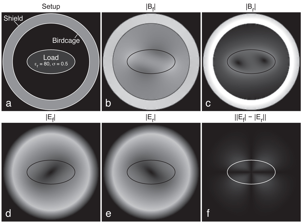
Simulations of a perfectly circular load in a balanced quadrature coil produced magnetic fields that exactly matched those predicted by the analytic expressions of Eqns 11–13. Fields simulated using the iteration of Eqn. 15 for an elliptical load are shown in Fig. 4. Scattering fields arising from the load disrupt the magnetic fields away from perfect circular polarization, with the forward field magnitude |Bf| (Fig. 4b) exhibiting significant sample-induced shading. Similarly, the excitatory component of the reversed field |Br| (Fig. 4c) includes some nonzero regions. In those locations, some signal would be generated in a reversed-polarization scan where complete suppression would be preferred.
Figure 4.
Finite-difference simulations of an elliptical object inside an ideal birdcage with a conductive shield (a). The forward and reversed magnetic fields (b,c) are affected by the object, with the reversed field producing a small amount of undesired excitation. Forward and reversed electric fields (d,e) increase with distance from the coil center, and show an asymmetry that inverts with the polarization change. The absolute difference in these magnitudes is shown in (f). Scaling is identical for (b) and (c), and also for (d), (e), and (f).
The electric fields generated in the forward and reversed modes, Ef and Er (Fig. 4d–e), generally increase in magnitude with distance from the center, as occurs for a circular load. In this case, however, a slight eccentricity has been introduced by the asymmetric load, the orientation of which is dependent on the polarization of the source field. Fig. 4f shows the magnitude of this difference in electric fields, ‖Ef| − |Er‖. The magnitude of this electric field difference is small compared to the total electric fields present, but nonetheless the electromagnetic environment can be materially changed by reversing the polarization of the applied field.
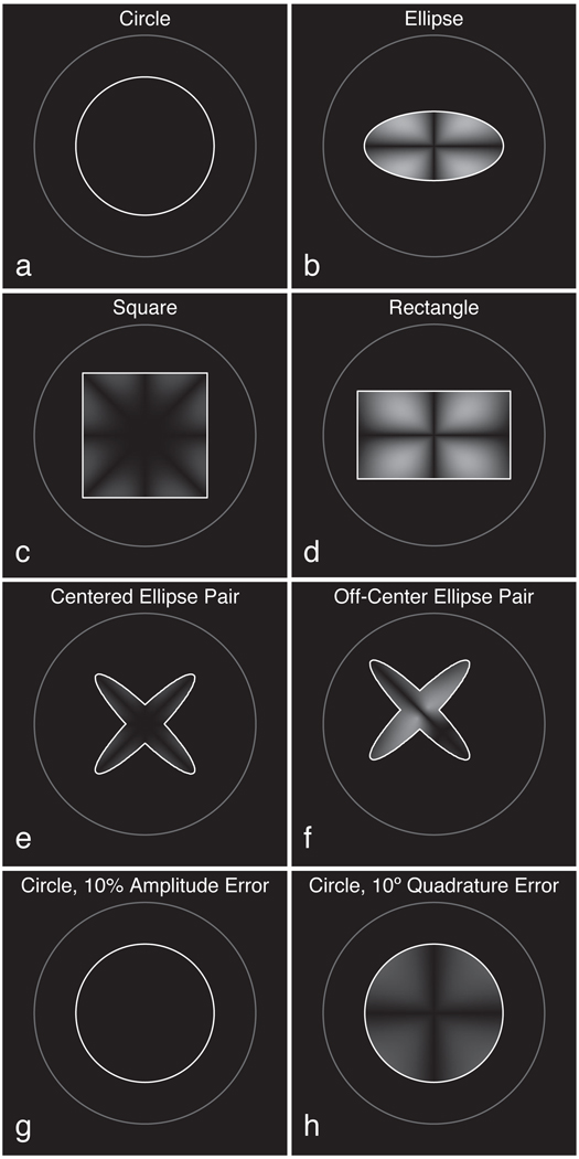
Figure 5 illustrates how these differences in electric fields upon polarization reversal are dependent upon load shape. Each panel of this figure shows the absolute difference ‖Ef| − |Er‖, where darker regions indicate smaller changes in electric field when polarization is reversed. Generally, symmetric loads create smaller distortions, while asymmetric loads result in larger distortions. Thus, circular (a) or square (c) loads are “preferable” to elliptical (b) or rectangular (d) ones. More complex objects like the ellipse pair (e) can also produce low distortion if they load the quadrature channels similarly, but this balance is destroyed if the object is moved significantly from isocenter (f). Even for the ideal circular load, hardware miscalibration may lead to E-field imbalance. For example, a 10° error in the quadrature phase of the applied current (h) leads to significant asymmetry in the E fields upon polarization reversal. Conversely, amplitude errors do not lead to any such distortion (g), as predicted by Eq. 8.
Figure 5.
Finite-difference simulations of electric field distortions, ‖Ef| − |Er‖. For circular (a), elliptical (b), square (c), and rectangular (d) loads, distortions are generally proportional to the degree of asymmetry in the load. A centered ellipse pair (e) produces relatively low distortion, but this increases as the object is moved off-center (f). A 10% amplitude imbalance in the coil’s drive current does not add distortion to the circular load (g), but a 10° error in its relative quadrature phase introduces a moderate error (h).
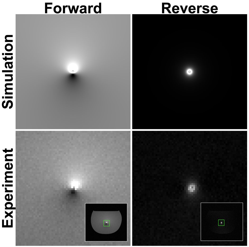
Simulated images arising from a wire coupled to a uniform forward-transmit, forward-receive, and to reverse-transmit, reverse-receive polarized fields are shown in Fig. 6. These images were derived from the wire fields of Eq. 10. Here, the wire current leads to a secondary B1 field for both excitation and reception. In the forward-polarized case, this secondary field interferes with the background excitation and leads to alternating regions of increased and decreased signal. In the reverse-polarized case, there is no background excitation to interfere, so the wire creates a symmetric signal pattern. These qualitative signal patterns were verified experimentally using a Nitinol guidewire immersed in water (Fig. 6, bottom).
Figure 6.
Simulated images of a 60-mA axial current (top) qualitatively agree with acquired images from a coupled guidewire (bottom).
Experimental Data
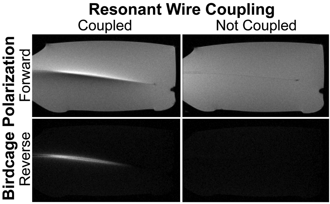
Figure 7 shows sagittal images of a bottle phantom with the end of a 150-cm guidewire extending through the 1-cm slice of interest. Both forward- and reversed-polarization images were acquired, demonstrating the expected complete suppression of background signal in the reversed-polarization images. In addition, these images were also acquired after the wire was cut short outside of the phantom (to approximately 20 cm). This shorter wire was unable to support antenna currents, and the reversed-polarization wire signal disappeared as expected.
Figure 7.
Phantom experiment. Images acquired using forward polarization (top) generate tip errors near unsafe currents, which can be difficult to distinguish from anatomy. When polarization is reversed (bottom), signal is generated only in the vicinity of unsafe currents. When the wire is shortened to eliminate antenna currents (right), reverse-polarization signal disappears.
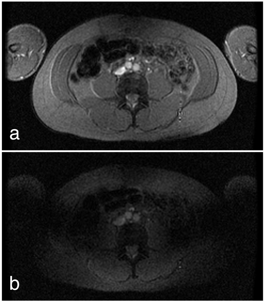
Fig. 8 shows example images acquired from the torso of a healthy volunteer using both forward and reversed RF polarization. These images were obtained using our relay-based implementation in order to allow the use of the body coil. In the reversed-polarization case, incomplete background suppression is apparent due to the lack of calibration of the quadrature channels as well as scattering from the asymmetric load.
Figure 8.
Forward-polarized (a) and reverse-polarized (b) images from the torso of a healthy volunteer depict the effects of imperfect background suppression. Imperfect background suppression arises both from quadrature miscalibration and from load-induced scattering fields.
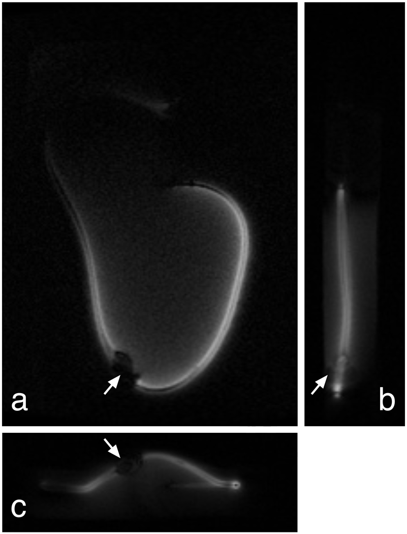
Three-plane projection images of a pacemaker lead, acquired using our direct-drive, dual-channel system, are shown in Figure 9. In each of these orthogonal projections, the reversed-polarization signal is clearly visualized around the lead, while signal away from the lead is largely suppressed. Even in axes where the projection dimension exceeds 24 cm, the background signal is sufficiently suppressed for identification of the lead currents.
Figure 9.
Pacemaker lead experiment. Reverse-polarization projection images in coronal (a), sagittal (b), and axial (c) planes clearly show the pacemaker lead, even when integrating over the 32-cm length of this gel phantom. A small ferromagnetic connector is present near the center of the lead (arrows), creating a small blowout artifact.
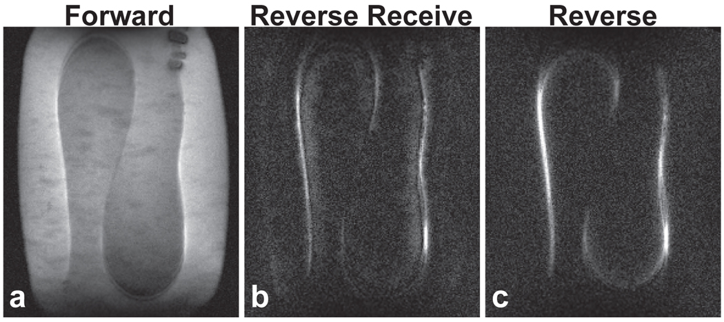
In the study of Fig. 10, a similar pacing lead of length 85 cm was placed in a different configuration in the gel phantom. This lead shape also supported significant coupling current. In Fig. 10b, the receiver polarization was reversed while the transmitter remained forward polarized. Fig 10c shows wire signal when both transmit and receive fields were reversed. The wire signal is qualitatively similar in each case, despite potential differences in E fields due to the asymmetric loading of this rectangular gel bath. However, the background in the reversed-receiver case is not as completely suppressed.
Figure 10.
Pacemaker lead. Projection images of an 85-cm pacing lead in a 36-cm gel phantom. (a): Forward polarization image shows conventional current artifacts. When the receiver polarization is reversed (b) or both transmitter and receiver are reversed in polarization (c), the background signal is well suppressed. Less signal cancellation in the vicinity of the wire is evident in the dually reversed image, along with slightly better background suppression.
Discussion
These preliminary results demonstrate that reversed-polarization imaging can be an effective method for quickly visualizing potentially dangerous wire currents. Projection images can be acquired with minimal deposited RF energy. These images show very good background suppression and clear wire signal even through thick projections.
Quadrature Calibration
Our reversed-polarization system incorporates a dual-channel direct-drive birdcage, which enables independent amplitude and phase (B1) shimming of the two linear birdcage modes. This is important to allow calibration of the source-field phase and amplitude under diverse loading conditions. Proper B1 shimming effectively creates a perfect quadrature source excitation at the ports, so that only the intrinsic source field and scattered field contribute to the composite field. Conventionally, birdcage systems used a single power amplifier and quadrature hybrid couplers, but this approach is inadequate for the precision quadrature balance needs of reversed-polarization imaging. The direct-drive approach should also be well suited to the inclusion of current sensors to provide mode feedback control in future implementations. With independent drive, we can also investigate whether separate linearly polarized excitations by I or Q are advantageous for assessing E-field asymmetry before applying polarization reversal.
Load Scattering
After quadrature calibration, residual signal errors in reversed-polarization images arise primarily from load scattering. Being the same wave effect that can cause RF shading, this phenomenon will be more significant at higher field strengths, but it cannot be discounted even at 1.5T. In our numerical models, the severity of the load scattering effect is strongly dependent upon the geometry and electromagnetic parameters of the simulation. The objective of these simulations was to demonstrate the fundamental properties of reverse polarization and the factors that degrade performance. We chose to model an infinitely long coil and a symmetric load because this represents one of the very few geometries for which an exact analytic solution is possible. This solution validated the finite-difference numerical simulations for loads of arbitrary two-dimensional cross section. However, these simulations also predicted significant scattering fields contributing an undesired B1 component to both left and right polarization. We did not see scattering fields of this magnitude in our experimental results at 1.5T. Specifically, the human result of Fig. 8 shows some residual error in the reversed-polarization mode, but the magnitude of this error is measurably lower than the corresponding residual B-field predicted in Fig. 4c. It should also be noted that the human result did not benefit from any quadrature calibration because it was obtained using our simpler relay-based hardware.
This discrepancy may be due to the model’s assumption of uniform electric properties and infinite conductor length. In contrast, the lipid layers and membrane structures of humans tend to inhibit RF eddy current generation since fat acts as an electrical insulator. Future simulation work should focus on accurate tissue models and finite-length coils and loads. A finite-difference time-domain (FDTD) birdcage model could enable these more realistic analyses, with the caveat that it will also numerically replicate quadrature port excitation imbalances with asymmetric loads.
Wire Currents
Estimation of wire current from conventional MR images is complicated by the presence of a large background signal (19, 20). Ideally, reversed-polarization imaging suppresses this background so that any remaining signal arises from RF current alone. Good background suppression can also highlight other local characteristics of the wire field. For example, in Fig. 10, whenever the wire is transverse to B0, the signal splits into a bright-dark-bright pattern because at those locations the RF field is entirely parallel to B0 directly above and below the wire. An intriguing null also exists halfway along the length of the wire, which may be a wave effect arising from cancellation of opposing currents from the wire’s ends. The 85 cm pacing lead falls between the free-space (235 cm) and immersed (26 cm) half-wavelengths. Both insulator thickness and electrode contact area will greatly influence the effective permittivity and dielectric loading that determine resonant length of the lead. Further study would be required to determine if this is indeed the case. Additionally, B1 mapping of the inhomogeneity differences during forward, reversed, or linearly polarized I and Q modes could give insight into the degree of E-field asymmetry that could occur with polarization reversal.
Relationship Between Current and Heating
While this technique provides an estimate for local wire current, the potential for heating is the quantity that is most relevant to the RF safety of the device. Fortunately, these two effects are intimately related. In fact, the Ohmic heating expected to arise from coupling is linearly dependent on contact resistance and quadratically on current (ΔT ∝ I2R). Thus, no Ohmic heating can exist without current. Indeed, this is the basis for RF ablation. In one study, Oh et al (30) deliberately injected 25–90 mA RF current for 60–90 seconds into the deep brain stimulator (DBS) electrodes of two patients. These RF current levels would create obvious flip angle artifacts in MRI as seen in the 60 mA case of Fig. 6.
However, the potential for heating is not so simply stated. A straight insulated guidewire in a conductive medium exhibits the well-known antenna current pattern of maximum current at its center decaying to zero at each end. Capacitive charge storage, on the other hand, is maximum at the tips, and its associated electric field could create dielectric breakdown under the right conditions. Stored charge can’t be detected by a current-measurement technique, but for standing-wave conditions to exist, there must be current flowing elsewhere on the wire. At resonance total electric field energy due to charge storage must equal magnetic field energy due to current. As long as the pre-scan procedure includes key lengths of the wire, any potential heating would be detected as current at some position on the wire. From this, we can conclude whether a dangerous condition exists, but the precise location of heating danger may not be known.
Differences Between Transmit and Receive Reversal
As described above, polarization reversal during receive alone ensures that the correct forward electric field is present during signal transmission, thereby providing the exact coupling environment that would be used during standard imaging. The disadvantage of this approach is that it suppresses unwanted background signal only during reception. By reversing signal polarization during both transmit and receive, background is doubly suppressed during both transmit and receive. However, this exposes the wire to the reversed electric field during transmit, which as we have shown is not necessarily equivalent to the forward field for asymmetric loads. Thus, receive-only reversal provides better wire-signal accuracy, while transmit/receive reversal provides better background suppression. Further research is needed to better understand this tradeoff.
In addition to these fundamental differences in signal, some practical concerns also arise. In our direct-drive birdcage, receiver polarization is synthesized in software from the two channels of received data, and both forward and reversed polarization images can be reconstructed from the same data set. This is not true in the transmit-reversed case, as the transmitted polarization must be linearly combined prior to excitation. Receive-mode polarization reversal is therefore more flexible than the transmit case, and one could also perform point-by-point spatial B1 calibration in the received data as is common in the SENSE literature.
Linearity
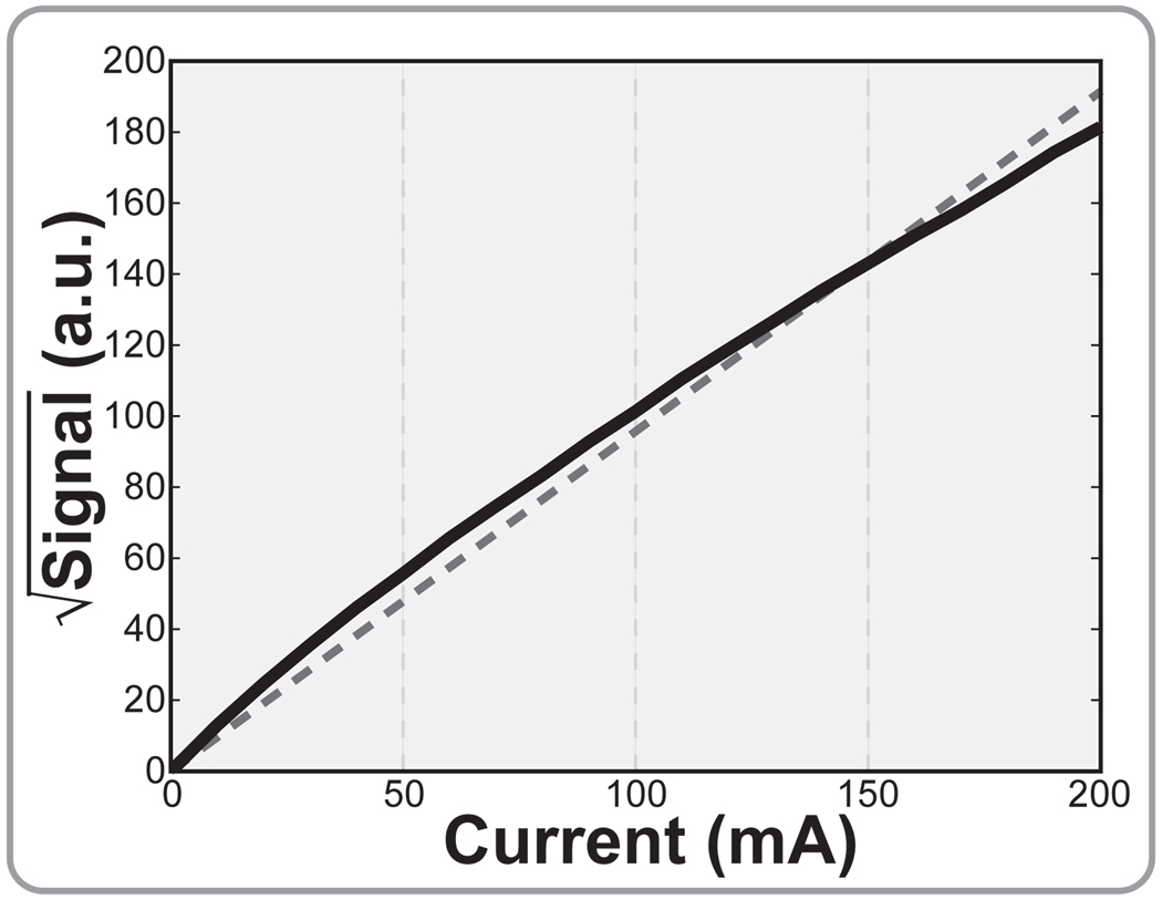
According to theory, the coupled B1 fields in both transmit and receive should scale linearly with induced currents. In the receive case, this translates directly into signal that is proportional to current. In the transmit case, the sinusoidal relationship between B1 and tip angle leads to a nonlinearity. However, since most of the excited volume arising from a wire transmitter is necessarily in the small-tip regime, this too can be assumed to be roughly linear with current. Thus, reversed-polarization images should have signal that scales roughly with the square of induced current–or, proportionally with induced power. Note that this power dependence is roughly true regardless of whether polarization reversal is employed during transmit, receive, or both, because the coupling occurs in all cases. Fig. 11 shows the simulated integrated signal arising from such an experiment as a function of induced current.
Figure 11.
Reversed-polarization signal is roughly proportional to the square of induced currents in the wire.
Techniques for Safely Detecting Coupling
In order to use polarization reversal to detect the potential for unsafe coupling, a controlled pre-scan procedure must be designed to ensure that the safety scan itself does not create unsafe heating under any coupling circumstances. Fortunately, reversed-polarization RF pulses can be flexibly integrated into a wide range of imaging techniques.
The simplest method for reducing RF heating is to minimize the total number of RF pulses used. For example, a single-shot EPI imaging sequence can acquire a 128×128 projection image with only one RF pulse. RF power can be further reduced by increasing the RF pulse duration for a given tip angle.
Still, care must be exercised to ensure that any potential heating is kept within a safe range. The U.S. Food and Drug Administration specifies that local tissue heating cannot exceed 2°C over the trunk (31, 32). Using the Pennes bioheat equation (33), we can ensure that the worst-case heating from a pre-scan experiment does not exceed this limit. Assuming no mitigating effects from perfusion or thermal diffusion, the RF-induced temperature rise is
| (16) |
where Cp is the specific heat of the tissue, tr f is the total RF duration, Pmax is the known maximum output power of the RF amplifier, and m is the equivalent mass over which the heating occurs. To approximate the worst-case heating for a given RF amplifier and coil, we specify a sufficiently small mass m over which to deposit this entire power.
For example, assume a tissue specific heat of 3660 J/Kg·°C and a 2-ms RF pulse. Our RF amplifiers are capable of 600 W in tandem output, and we consider the absolute worst case that this entire power is deposited into one gram of tissue. This mass is chosen in part because it represents an order of magnitude of additional safety over the internationally accepted standard for localized SAR to be averaged over 10 g of tissue (34). Using these values, the maximum calculated temperature rise for a single-shot experiment is 0.33°C, well below established limits.
Thus, we can safely perform any single-shot experiment using this experimental setup with confidence that unsafe heating will not occur. For other equipment, a similar approach may be used to determine maximum safe RF limits regardless of coupling. For higher-power amplifiers, it may be necessary to scale RF pulse amplitudes to ensure safety. Generalizing the above analysis, RF pulse amplitudes should be scaled using
| (17) |
to ensure that the instantaneous torso SAR limit cannot be exceeded under any circumstances.
Once such a reduced-power scan is completed, the collected data may then be used to refine the estimate of coupling between patient and implant. If this data analysis reveals no detectable wire current, or current levels well below the safety limit, then additional images could be safely acquired at a higher transmitted power. This could continue using progressively higher-power RF excitations until a reliable estimate of wire coupling is determined, or until it is apparent that quantifiable coupling does not exist even at the highest transmitted power levels.
Conclusion
We have demonstrated a new technique for rapidly detecting the presence of dangerous B1 coupling using reversed circular polarization. When used as a pre-scan procedure prior to the deposition of significant RF power, this technique may permit patients currently contraindicated for MR to undergo needed scans. Care must be taken to address imperfections in the resulting electrical and magnetic fields, but these anomalies are well understood and should not prohibit the technique from being used as an early warning mechanism.
Acknowledgments
This work was supported by NIH (R01EB008108) and GE Healthcare.
References
- 1.Snow JS, Kalenderian D, Colasacco JA, Jadonath RL, Goldner BG, Cohen TJ. Implanted devices and electromagnetic interference: case presentations and review. J Invasive Cardiol. 1995;7:25–32. [PubMed] [Google Scholar]
- 2.Ahmed S, Shellock FG. Magnetic resonance imaging safety: implications for cardiovascular patients. J Cardiovasc Magn Reson. 2001;3:171–182. doi: 10.1081/jcmr-100107466. [DOI] [PubMed] [Google Scholar]
- 3.Naehle CP, Meyer C, Thomas D, Remerie S, Krautmacher C, Litt H, Luechinger R, Fimmers R, Schild H, Sommer T. Safety of brain 3-T MR imaging with transmit-receive head coil in patients with cardiac pacemakers: pilot prospective study with 51 examinations. Radiology. 2008;249:991–1001. doi: 10.1148/radiol.2493072195. [DOI] [PubMed] [Google Scholar]
- 4.Sommer T, Naehle CP, Yang A, Zeijlemaker V, Hackenbroch M, Schmiedel A, Meyer C, Strach K, Skowasch D, Vahlhaus C, Litt H, Schild H. Strategy for safe performance of extrathoracic magnetic resonance imaging at 1.5 tesla in the presence of cardiac pacemakers in non-pacemaker-dependent patients: a prospective study with 115 examinations. Circulation. 2006;114:1285–1292. doi: 10.1161/CIRCULATIONAHA.105.597013. [DOI] [PubMed] [Google Scholar]
- 5.Nitz WR, Oppelt A, Renz W, Manke C, Lenhart M, Link J. On the heating of linear conductive structures as guide wires and catheters in interventional MRI. J Magn Reson Imaging. 2001;13:105–114. doi: 10.1002/1522-2586(200101)13:1<105::aid-jmri1016>3.0.co;2-0. [DOI] [PubMed] [Google Scholar]
- 6.Gray RW, Bibens WT, Shellock FG. Simple design changes to wires to substantially reduce MRI-induced heating at 1.5 T: implications for implanted leads. Magn Reson Imaging. 2005;23:887–891. doi: 10.1016/j.mri.2005.07.005. [DOI] [PubMed] [Google Scholar]
- 7.Ladd ME, Quick HH. Reduction of resonant RF heating in intravascular catheters using coaxial chokes. Magn Reson Med. 2000;43:615–619. doi: 10.1002/(sici)1522-2594(200004)43:4<615::aid-mrm19>3.0.co;2-b. [DOI] [PubMed] [Google Scholar]
- 8.Weiss S, Vernickel P, Schaeffter T, Schulz V, Gleich B. Transmission line for improved RF safety of interventional devices. Magn Reson Med. 2005;54:182–189. doi: 10.1002/mrm.20543. [DOI] [PubMed] [Google Scholar]
- 9.Yeung CJ, Susil RC, Atalar E. RF safety of wires in interventional MRI: using a safety index. Magn Reson Med. 2002;47:187–193. doi: 10.1002/mrm.10037. [DOI] [PubMed] [Google Scholar]
- 10.Nazarian S, Roguin A, Zviman MM, Lardo AC, Dickfeld TL, Calkins H, Weiss RG, Berger RD, Bluemke DA, Halperin HR. Clinical utility and safety of a protocol for non-cardiac and cardiac magnetic resonance imaging of patients with permanent pacemakers and implantable-cardioverter defibrillators at 1.5 tesla. Circulation. 2006;114:1277–1284. doi: 10.1161/CIRCULATIONAHA.105.607655. [DOI] [PMC free article] [PubMed] [Google Scholar]
- 11.Martin ET, Coman JA, Shellock FG, Pulling CC, Fair R, Jenkins K. Magnetic resonance imaging and cardiac pacemaker safety at 1.5-tesla. J Am Coll Cardiol. 2004;43:1315–1324. doi: 10.1016/j.jacc.2003.12.016. [DOI] [PubMed] [Google Scholar]
- 12.Wollmann C, Grude M, Tombach B, Kugel H, Heindel W, Breithardt G, Bocker D, Vahlhaus C. Safe performance of magnetic resonance imaging on a patient with an ICD. Pacing Clin Electrophysiol. 2005;28:339–342. doi: 10.1111/j.1540-8159.2005.09535.x. [DOI] [PubMed] [Google Scholar]
- 13.Rezai AR, Baker KB, Tkach JA, Phillips M, Hrdlicka G, Sharan AD, Nyenhuis J, Ruggieri P, Shellock FG, Henderson J. Is magnetic resonance imaging safe for patients with neurostimulation systems used for deep brain stimulation? Neurosurgery. 2005;57:1056–1062. doi: 10.1227/01.neu.0000186935.87971.2a. [DOI] [PubMed] [Google Scholar]
- 14.Henderson JM, Tkach J, Phillips M, Baker K, Shellock FG, Rezai AR. Permanent neurological deficit related to magnetic resonance imaging in a patient with implanted deep brain stimulation electrodes for parkinson’s disease: case report. Neurosurgery. 2005;57:E1063. doi: 10.1227/01.neu.0000180810.16964.3e. discussion E1063. [DOI] [PubMed] [Google Scholar]
- 15.Graf H, Lauer UA, Berger A, Schick F. RF artifacts caused by metallic implants or instruments which get more prominent at 3 T: an in vitro study. Magn Reson Imaging. 2005;23:493–499. doi: 10.1016/j.mri.2004.12.009. [DOI] [PubMed] [Google Scholar]
- 16.Graf H, Steidle G, Martirosian P, Lauer UA, Schick F. Effects on MRI due to altered RF polarization near conductive implants or instruments. Med Phys. 2006;33:124–127. doi: 10.1118/1.2132571. [DOI] [PubMed] [Google Scholar]
- 17.Quick HH, Zenge MO, Kuehl H, Kaiser G, Aker S, Massing S, Bosk S, Ladd ME. Interventional magnetic resonance angiography with no strings attached: wireless active catheter visualization. Magn Reson Med. 2005;53:446–455. doi: 10.1002/mrm.20347. [DOI] [PubMed] [Google Scholar]
- 18.Celik H, Uluturk A, Tali T, Atalar E. A catheter tracking method using reverse polarization for MR-guided interventions. Magn Reson Med. 2007 Dec;58:1224–1231. doi: 10.1002/mrm.21419. [DOI] [PubMed] [Google Scholar]
- 19.Scott GC, Joy MG, Armstrong RL, Henkelman RM. Electromagnetic considerations for RF current density imaging [MRI technique] IEEE Trans Med Imaging. 1995;14:515–524. doi: 10.1109/42.414617. [DOI] [PubMed] [Google Scholar]
- 20.Venook R, Overall W, Shultz K, Conolly S, Pauly J, Scott G. Monitoring induced currents on long conductive structures during MRI. Proceedings of the 16th Annual Meeting of ISMRM; Toronto. 2008. p. 898. [Google Scholar]
- 21.Kales M. Techniques for handling elliptically polarized waves with special reference to antennas. Part 3, elliptically polarized waves and antennas. Proceedings of the Institute of Radio Engineers. 1951;39:544–549. [Google Scholar]
- 22.Balanis CA. Advanced engineering electromagnetics. New York: Wiley; 1989. [Google Scholar]
- 23.Rumsey VH. Reaction concept in electromagnetic theory. Phys Rev. 1954;94:1483–1491. [Google Scholar]
- 24.Villeneuve A, Harrington R. Reciprocity relationships for gyrotropic media. IRE Transactions on Microwave Theory and Techniques. 1958;6:308–310. [Google Scholar]
- 25.Hayes CE, Edelstein WA, Schenck JF, Mueller OM, Eash M. An efficient, highly homogeneous radiofrequency coil for whole-body NMR imaging at 1.5 T. J Magn Reson. 1985;63:622–628. [Google Scholar]
- 26.Jin J. Electromagnetic Analysis and Design in Magnetic Resonance Imaging. Boca Raton: CRC Press; 1999. [Google Scholar]
- 27.Stang P, Conolly S, Pauly J, Scott G. MEDUSA: A scalable MR console for parallel imaging. Proceedings of the 15th Annual Meeting of ISMRM; Berlin. 2007. p. 925. [Google Scholar]
- 28.Overall WR, Pauly JM. An extensible, graphical environment for pulse sequence design and simulation. Proceedings of the 15th Annual Meeting of ISMRM; Berlin. 2007. p. 1652. [Google Scholar]
- 29.Park SM, Nyenhuis JA, Smith CD, Lim EJ, Foster KS, Baker KB, Hrdlicka G, Rezai AR, Ruggieri P, Sharan A, Shellock FG, Stypulkowski PH, Tkach J. Gelled vs. non-gelled phantom material for measurement of MRI-induced temperature increases with bioimplants. IEEE Trans. Magn. 2003;39:3367–3369. [Google Scholar]
- 30.Oh M, Hodaie M, Kim S, Alkhani A, Lang A, Lozano A. Deep brain stimulator electrodes used for lesioning: Proof of principle. Neurosurgery. 2001;49:363–369. doi: 10.1097/00006123-200108000-00018. [DOI] [PubMed] [Google Scholar]
- 31.U.S. Department of Health and Human Services, Food and Drug Administration, Center for Devices and Radiological Health. Guidance for Industry: Guidance for the Submission Of Premarket Notifications for Magnetic Resonance Diagnostic Devices. 1998 November
- 32.Athey TW. Current FDA guidance for MR patient exposure and considerations for the future. Ann N Y Acad Sci. 1992;649:242–257. doi: 10.1111/j.1749-6632.1992.tb49613.x. [DOI] [PubMed] [Google Scholar]
- 33.Pennes HH. Analysis of tissue and arterial blood temperatures in the resting human forearm. J Appl Physiol. 1948;1:93–122. doi: 10.1152/jappl.1948.1.2.93. [DOI] [PubMed] [Google Scholar]
- 34.Particular requirements for the safety of magnetic resonance equipment for medical diagnosis. 2004. Jan, International Electrotechnical Commission Standard 60601-2-33. [Google Scholar]
- 35.Nordbeck P, Fidler F, Weiss I, Warmuth M, Friedrich MT, Ehses P, Geistert W, Ritter O, Jakob PM, Ladd ME, Quick HH, Bauer WR. Spatial distribution of RF-induced E-fields and implant heating in MRI. Magn Reson Med. 2008 Aug;60:312–319. doi: 10.1002/mrm.21475. [DOI] [PubMed] [Google Scholar]


