Abstract
An efficient planar micromixer based on multidirectional vortices in a curved channel with radial baffles is proposed and examined in this work. The curvature of the microchannel and the radial baffles induce vortices in different directions. The multidirectional vortices and the converging-diverging flow caused by the baffles contribute together to the enhancement of mixing. The micromixer is fabricated with polydimethylsiloxane by a single planar microlithography process and the mixing behaviors are observed by a confocal spectral microscope imaging system to validate the simulation obtained by a commercial code. The simulation and experimental results are in reasonable agreement. The concentration distributions and flow patterns obtained reveal the following trends. (i) The mixing efficiency of the basic C-shaped micromixer with the first baffle attached to the internal cylinder and the second attached to the external cylinder is better than that of the C-shaped micromixer with inverted arrangement of baffles. (ii) When the radius of the curved channel and the width of the passage between the baffle and the cylindrical wall are small enough and the Reynolds number (Re) is large enough, an extra separation vortex develops in the downstream of the second baffle. This phenomenon is one of the reasons of trend (i). (iii) A micromixer consisting of a few basic C-shaped micromixers connected by straight channels may generate a high degree of mixing for the case with a large Re.
INTRODUCTION
Micromixer is an important component in many microfluidic systems applied in biochemistry analysis, because many biochemical processes require rapid and complete mixing.1, 2, 3 Due to the small channel size of a microfluidic system, the flow is usually laminar, and so the mixing of fluids in the system remains a challenge.
In recent years, researchers have developed many ingenious micromixers, including active micromixers and passive micromixers.4, 5 Active micromixers utilize some forms of active control, including moving parts or external forces, upon the flow field. Passive micromixers do not require external energy except that used to drive the flows. Thus, enhancing mixing in passive micromixers relies on the features of microchannel geometry, which increases the interfacial area of different fluids or decreases the diffusion length. In general, the mixing efficiency of active micromixers is better than that of passive micromixers. However, it is simpler to fabricate passive micromixers and easier to integrate them with microfluidic systems. Therefore, passive micromixers still gain attention and have been developed widely.
Various microchannel structures such as bending, curved, and∕or converging-diverging channel, and other designs such as lamination, hydrodynamic focusing, and impinging have been developed to enhance the mixing of fluids in passive micromixers. Besides, three-dimensional channel structures are used to induce chaotic advection at lower Reynolds number.6, 7, 8 In general, the three-dimensional channel structures are effective for fluid mixing. However, the fabrication processes of micromixers with three-dimensional structures are more complicated than those of the planar micromixers.
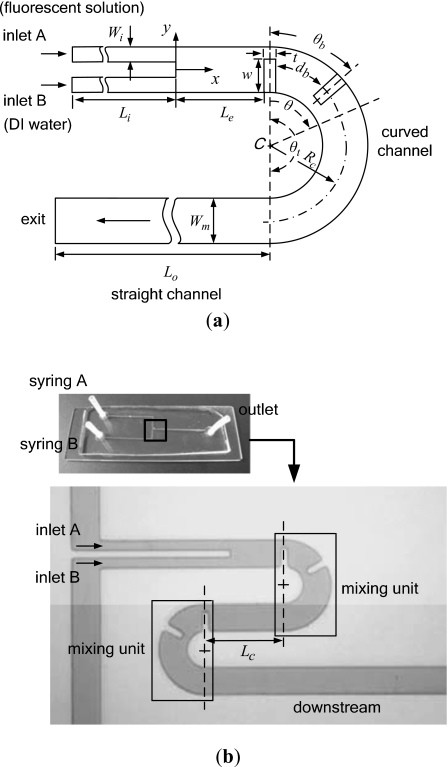
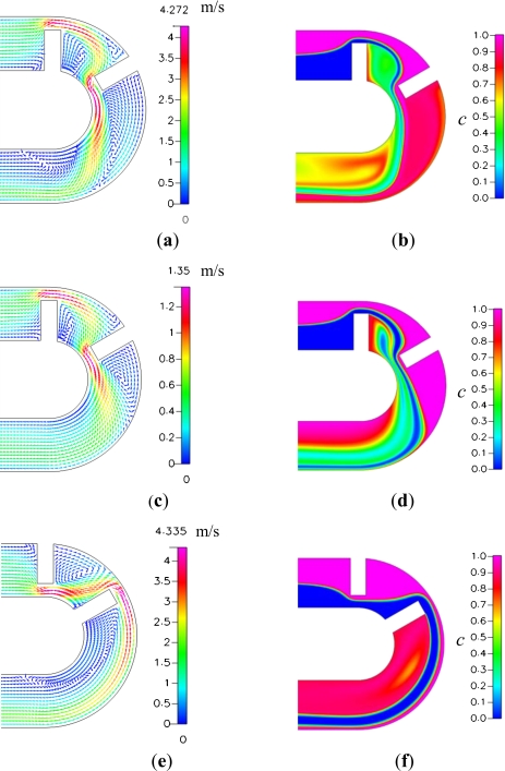
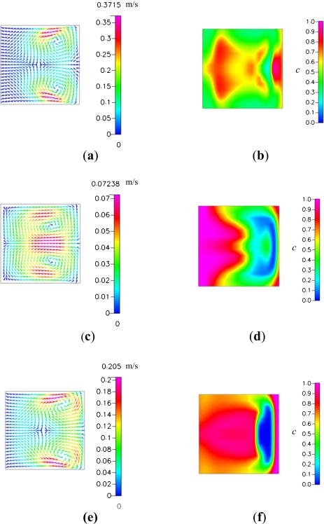
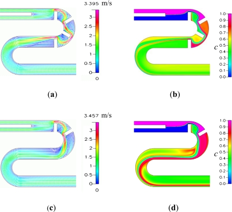
The strategies to improve fluid mixing in planar micromixers include lamination,9, 10 hydrodynamic focusing,11 using curved microchannels,12 and flow separation arising from the interaction of geometrical structures and fast flow.13, 14, 15, 16 In this work we investigate the enhancement of fluid mixing by building radial baffles into a curved planar microchannel, as shown in Fig. 1. The effects of the microchannel curvature12 and those of baffles or obstacles in a microchannel14, 15, 16, 17 on fluid mixing have been investigated separately. However, we have seldom seen work investigating fluid mixing in a curved microchannel with obstacles or baffles. Tang et al.18 considered mixing of slug contents by folding slugs in a curved microchannel with obstacles. In the micromixers proposed in this work, the Dean vortices due to the curvature of a planar microchannel19 and those results from the radial baffles are in different directions. Besides, the acceleration of main stream as the flow through a passage between the baffle and the channel wall with a small radius may cause additional flow separation in the downstream of the baffles for a high Reynolds number flow, as shown by the comparison of Figs. 2a, 2c. Thus, we expect that building radial baffles into a curved planar microchannel with suitable arrangements may improve fluid mixing in the proposed micromixer. Experiment and numerical simulation of fluid mixing in micromixers with various radii of microchannel and arrangements of baffles are performed to investigate the efficiency of the proposed micromixer.
Figure 1.
(a) Schematic diagram of the basic C-shaped micromixer and (b) overall view of the fabricated CSC micromixer (Rc=160 μm).
Figure 2.
Flow patterns and concentration distributions on the horizontal plane z=65 μm: [(a) and (b)] the basic C-shaped micromixer (Rc=160 μm) at Re=81, [(c) and (d)] the basic C-shaped micromixer (Rc=160 μm) at Re=27, and [(e) and (f)] the C-shaped micromixer (Rc=160 μm) with inverted baffles at Re=81.
MICROMIXER DESIGN
A schematic example of the proposed micromixer is shown in Fig. 1a. The design includes a curved microchannel with two radial baffles, two straight inlets, and an exit microchannel. The inlets have a rectangular cross section of Wi=45 μm by H=130 μm and a length Li of 650 μm. The length of the straight channel from the inlets to the first baffle is Le=260 μm and the straight channel connecting the end of the curved channel and the exit has a length Lo=1950 μm. The curved microchannel with a radius (Rc) over the angular range θt is the main part in which mixing is enhanced. The curved microchannel and the straight exit microchannel have a rectangular cross section of Wm=130 μm by H=130 μm. Besides, the baffle thickness (t) equals to 40 μm, the width of the radial baffles (w) equals to 97.5 μm. In order to examine the enhancement of mixing by the channel curvature, we shall consider fluid mixing in the curved channels with the same length and various curvature radii. Besides, the effects of baffle arrangements and numbers of baffles and curved channels are investigated. For convenience, we call the curved channel with θt=180° and two baffles a mixing unit. In the following investigation, we shall find that the mixing efficiency of the micromixer shown in Fig. 1a with db≈Wm, the first baffle attached to the internal cylinder and the second attached to the external cylinder, is better than other micromixers with different arrangements of baffles. Thus, we call the micromixer with the first baffle attached to the internal cylinder and the second attached to the external cylinder a basic C-shaped micromixer. Two mixing units may be connected by a straight channel with Lc=390 μm to form a curved-straight-curved (CSC) micromixer, as shown in Fig. 1b. The CSC micromixer has a longer channel, more baffles, and better mixing efficiency.
NUMERICAL SIMULATIONS
The numerical simulations of the flow in the micromixer are conducted by the commercial code CFD-ACE+(CFD Research Corporation, CA, USA). The governing equations include the continuity equation, the momentum equation, and the species convection-diffusion equation for isothermal steady incompressible flows. In this work, the fluids entering the two inlets are assumed to possess properties of water and we consider equal flow rate at both inlets. The mole concentration fractions of solutions are set to be 1 (fluorescent solution) at inlet A and 0 [deionized (DI) water] at inlet B, respectively. The density, the viscosity, and the diffusion coefficient of Rhodamine B (Fluka, Germany) in DI water are 997 kg m−3, 0.000 97 kg m−1 s−1, and 3.6×10⁻¹⁰ m2 s−1,20 respectively. The boundary conditions of uniform inlet velocities corresponding to Reynolds numbers of 0.054, 0.23, 1, 3, 9, 27, and 81 are considered. Here, the Reynolds number is defined as , where , dh, and v denote the mean velocity of the downstream flow, the hydraulic diameter of the main channel, and the kinematic viscosity of the fluid, respectively. Those values of Re are selected to cover the range of flows from the diffusion domination to the convection domination of the mixing in the channel. The outlet pressure is set to be 1 atm. Furthermore, the no-slip condition is set on the solid walls.
The SIMPLEC algorithm is used for pressure-velocity coupling. The spatial difference is performed by utilizing the second-order upwind scheme with limiter and the algebraic multigrid solver. To minimize the effect of the numerical diffusion on simulation results, we use the cells with varying sizes. The solution is considered to be converged when the relative residual of each variable is less than 0.0001.
To quantify mixing, the degree of mixing, M,21 at the exit of the micromixer is calculated by
| (1) |
where σ is the standard deviation of mole concentration fraction at a transverse cross section. Here,
| (2) |
where n denotes the total number of sampling, ci the mole concentration fraction at a position on the cross section considered, and the average of ci.
FABRICATION AND EXPERIMENT SETUP
The fluid mixing is performed in a sealed polydimethylsiloxane (PDMS)-glass chip. The PDMS microchannel is formed by casting on a SU-8 (50) photoresist mold. Initially, single-side polished silicon wafers are cleaned and dehydrated, and negative photoresist SU-8 is coated on a wafer by spin coating. Then, the wafer with SU-8 film is heated on a hotplate for 15 min at 65 °C and 45 min at 95 °C. Furthermore, the wafer with SU-8 film is exposed to 365 nm UV light at 240 mJ cm−2 to pattern the channel of the micromixer and then heated for 10 min at 65 °C and 15 min at 95 °C. After the development process, the SU-8 master mold with 130 μm thickness can be obtained. Once the mold is finished, the PDMS and the curing agent are mixed at an 8:1 ratio, and poured onto the SU-8 mold. Next, the workpiece is pumped under vacuum to degas air from the PDMS and then it is cured for 60 min at 100 °C by a vacuum drying oven. After the PDMS is peeled off from the mold, both the PDMS and a sheet of glass are treated with oxygen plasma, and then bonded to form the micromixer. Figure 1b shows an overall view of the fabricated CSC micromixer for further investigations.
The experimental apparatus to verify the mixing behaviors includes two parts: the fluid flow system and the image processing system. During experiment, two syringes are connected to the inlets of the micromixer shown in Fig. 1b. One syringe is filled with fluorescent solution, while the other is filled with DI water. The two syringes are driven at constant flow rates by a syringe pump (KDS 101, KD Scientific, USA). A confocal spectral microscope imaging system (Leica TCS SP2, Leica Corp., Germany) is used to acquire the images of mixing in the micromixer. The signal of the fluorescent emission excited at 543 nm with a HeNe green laser can be detected in red (585–615 nm). In this work, the images of concentration distributions on the horizontal cross section and those on the vertical cross section of the flow are obtained by scanning over the horizontal and the vertical cross sections, respectively. An image processing software (IMAGEJ) is used to extract the gray-scale values of the images. The gray-scale values at the vertical cross sections considered are normalized by the average gray-scale value of the fluorescent emission from the solution at the inlet. Using the normalized gray-scale values instead of ci in Eqs. 1, 2, we can calculate the degree of mixing from Eqs. 1, 2, where n is the total number of pixels, and is the average of the normalized gray-scale values.
RESULTS AND DISCUSSION
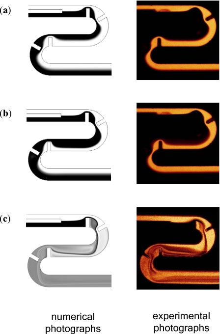
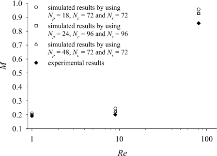
Before evaluating the performance of the proposed micromixers, we validate the modeling and simulation described above. Figure 3 shows that the concentration distributions on the horizontal midplane of the CSC micromixer shown in Fig. 1b at Re=1, 9, and 81 obtained by simulation are in reasonable agreement with those obtained by experiment. The simulation results shown in Fig. 3 are obtained by using cells with varying size. The simulated degrees of mixing obtained by using three different sets of cells and that obtained by experiment are in reasonable agreement with each other, as shown in Fig. 4. We refer to Lm=Le+2θtRc+Lc+Lo as the total length of mixing channel for comparisons of the degree of mixing. Lm=3605 μm for the CSC micromixer shown in Fig. 1b. The three sets of cells have the same 27 cells in the vertical direction (normal to x-axis and y-axis) over the whole micromixer. The number of cells in the tangential direction in each of the curved channels is set to be 278, and the numbers of cells in the tangential direction (x-direction) in each of the straight channels with the length, Le, Lc, and Lo, are set to be 108, 216, and 360, respectively. The distinctions among the three sets of cells are the distribution of cells in the radial direction for the curved channels. The number of cells in the y-direction for the straight channels is set to be the same as that in the radial direction in the part of curved channel without baffles. Two of the three sets have uniform cell sizes in the radial direction (Δr), while the other set has varying Δr. The set of cells with varying Δr has the smallest cells in the passages, where the flow speed and the numerical diffusion are relatively large for the case with a large Re. Comparison in Fig. 4 shows that (i) the discrepancy between the simulation and the experiment increases with the increase of Re, (ii) the discrepancy is due to numerical diffusion which can be reduced by using smaller cells in the calculation, and (iii) using a set of cells with smallest cells in the passage can improve the simulation results efficiently. Thus, we use the set of cells with varying Δr in the simulation shown in Fig. 3 and in the following simulation for the cases with built-in baffles.
Figure 3.
Concentration distributions on the horizontal midplane of the flows with (a) Re=1, (b) Re=9, and (c) Re=81 in the CSC micromixer (Rc=160 μm).
Figure 4.
Degrees of mixing at the exit of the CSC micromixer (Rc=160 μm, Lm=3605 μm) shown in Fig. 3 for the cases with Re=1, 9, and 81; here N is the number of cells and the subscript s denotes the y-direction in the straight channels, p denotes the radial direction in the passages between the baffles and the cylindrical walls, and c denotes the radial direction in the parts of curved channels without a baffle.
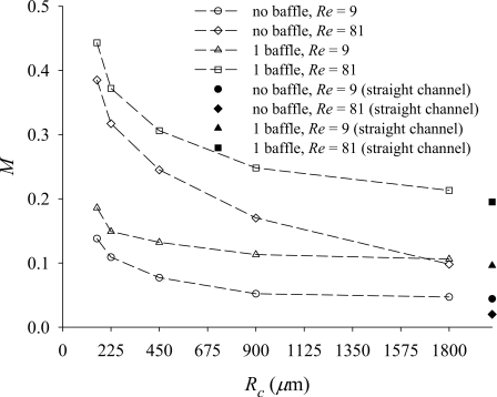
First, we examine the influence of the radius of microchannel and a single baffle built in the microchannel. Figure 5 shows the degree of mixing at the exit cross section for two types of micromixers, one with a radial baffle attached to the internal cylinder and the other without a baffle at Re=9 and 81. For comparison purpose, the degrees of mixing of the limiting cases with a straight channel are also shown in Fig. 5. The length of the curved channel, Le+θtRc+Lo, and the total length of the straight channels are set to be the same. From Fig. 5 we may find the following trends. (i) Building a radial baffle into a curved channel enhances the fluid mixing. (ii) The Dean vortices improve mixing, especially for the case with a smaller radius of curvature and a larger Reynolds number. Hence, the fluid mixing in the curved channel with a baffle is better than that in the straight channel with a baffle. (iii) When the Reynolds number is large enough, the degree of mixing of a microchannel with a small enough radius and without a baffle may be greater than that of a straight microchannel with a single baffle.
Figure 5.
Effects of Rc on the degrees of mixing at the exit of the microchannels with a baffle or without a baffle (Lm=2712 μm) for the cases with Re=9 and 81.
Next, the fluid mixing in a microchannel with a small radius and a pair of baffles (θb=60°) is investigated. We consider two arrangements. One is the basic C-shaped micromixer shown in Fig. 1a, while another is the C-shaped micromixer with the first baffle attached to the external cylinder and the second to the internal cylinder, as shown in Figs. 2e, 2f. Comparison of Figs. 2b, 2f, 6b, 6f shows that the mixing efficiency of the basic C-shaped micromixer is superior to that of the C-shaped micromixer with inverted baffles. When the radius of the curved channel (Rc) and the width of the passage between the baffles and the channel wall (W−w) compared with the width of the channel are small enough and the Reynolds number is large enough, an extra separation vortex develops in the downstream of the second baffle attached to the external cylinder of a basic C-shaped micromixer, as shown in Fig. 2a. This is one of the reasons why the basic C-shaped micromixer is superior to the C-shaped micromixer with inverted baffles. For the case with a smaller Reynolds number [Figs. 2c, 2d] or that with inverted baffles [Figs. 2e, 2f], the flow field does not have the extra separation vortex around the internal channel wall. Later, we shall present a quantitative comparison of the degrees of mixing of the channels with four baffles, two baffles, and without baffles.
Figure 6.
Flow patterns and concentration distributions on the transverse cross section at θ=180°: [(a) and (b)] the basic C-shaped micromixer (Rc=160 μm) at Re=81, [(c) and (d)] the basic C-shaped micromixer (Rc=160 μm) at Re=27, and [(e) and (f)] the C-shaped micromixer (Rc=160 μm) with inverted baffles at Re=81.
Figures 26 also show the following trends. (i) In the micromixer with the second baffle attached to the external cylinder, as shown in Figs. 2a, 2c, the mainstream flowing through the second passage is pushed by the centrifugal force from the internal cylinder to the external cylinder. (ii) In the micromixer with the second baffle attached to the internal cylinder, as shown in Figs. 2e, 2f, the mainstream through the second passage flows along the external cylinder and the expansion vortex behind the baffle attached to the internal cylinder. (iii) The lateral convection on the transverse cross section at θ=180° of the flow in the basic C-shaped micromixer [Fig. 6a] is much greater than that of the flow in the C-shaped micromixer with inverted baffles [Fig. 6e]. These trends are the other reasons why the basic C-shaped micromixer is superior to the C-shaped micromixer with inverted baffles.
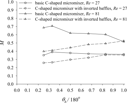
To investigate the effects of the distance between the two neighboring radial baffles (Rc×θb) on fluid mixing, we simulate the mixing flow for the basic C-shaped micromixer and the C-shaped micromixer with inverted baffles for various values of θb∕180°. In general, the mixing performance of the former is better than that of the latter, as shown in Fig. 7. The basic C-shaped micromixer with θb=60° generates the optimum mixing efficiency for the cases dominated by convection (Re=27 and 81). This is because the two baffles attached to the basic C-shaped micromixer with θb=60° generate a stronger vortex behind the first baffle than that generated by other baffle arrangement. Besides, the second baffle in the case of θb>90° has nearly no effect on the formation of the recirculation zone behind the first baffle. As for the C-shaped micromixer with inverted baffles, it generates the optimum mixing efficiency as θb approaches 180°. The reasons for this trend are that the mixing is dominated by the lateral advection caused by the inertia force and the continuous action of centrifugal force as the flow passes the radial baffle attached to the external cylinder, and a large baffle distance (θb>90°) for the cases dominated by convection (Re=27 and 81) allows the development of an extra separation vortex similar to that shown in Fig. 2a.
Figure 7.
Degrees of mixing at the exits of the basic C-shaped micromixer (Rc=160 μm, Lm=2712 μm) and the C-shaped micromixer with inverted baffles (Rc=160 μm, Lm=2712 μm) for various values of θb∕180°.
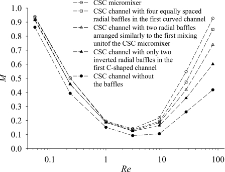
According to the above comparisons, we propose that the CSC micromixer consists of two mixing units and a straight microchannel, as shown in Fig. 1b. Each of the mixing units is a basic C-shaped mixer with θb=60°. Figure 8 shows the degree of mixing at the exit cross section for the CSC micromixer and other four micromixers. These four micromixers include two curved microchannels connected by a straight channel to form a CSC microchannel. Thus, they also have the same channel geometry and size as the CSC micromixer except the baffle number and location. The proposed CSC micromixer generates the largest degree of mixing and its value is greater than 90% at the exit for the case with Re=81. As expected, the degrees of mixing of the CSC micromixer and the CSC channel with four equally spaced radial baffles in the first curved channel are greater than those of the CSC channels with only two radial baffles. In general, the degree of mixing decreases with the decrease of the number of the radial baffles. Figure 8 reveals that the degree of mixing of the CSC micromixer is greater than that of the CSC channel with four equally spaced baffles in the first curved channel for the cases dominated by convection. This is because there is no large enough space between the second radial baffle and the third radial baffle to develop the flow pattern good for mixing in the CSC channel with four equally spaced baffles, as shown in Figs. 9a, 9b. Figure 8 also shows that the degree of mixing of the CSC channel with only two radial baffles arranged similarly to the first mixing unit of the CSC micromixer is larger than the degree of mixing of the CSC channel with only two inverted radial baffles in the first C-shaped channel. The arrangement of the inverted radial baffles is similar to that shown in Fig. 2e or Fig. 2f. Figures 9c, 9d show that there is an extra separation vortex in the downstream of the first curved channel for the case with Re=81. Besides, when the Reynolds number is large (Re>3), the difference of the degrees of mixing of the five micromixers increases with the increase of Reynolds number, as shown in Fig. 8. The increase of Reynolds number corresponds to the increase of contribution of the lateral advection to the fluid mixing and the arrangement of the radial baffles is important for the performance of the proposed micromixers in the high Reynolds number region.
Figure 8.
Degrees of mixing at the exits of the CSC micromixer (Rc=160 μm, Lm=3605 μm) and four other micromixers (Rc=160 μm, Lm=3605 μm) for the cases with Re=0.054, 0.23, 1, 3, 9, 27, and 81.
Figure 9.
Flow patterns and concentration distributions on the horizontal plane z=65 μm for the case with Re=81: [(a) and (b)] the CSC channel (Rc=160 μm, Lm=3605 μm) with four equally spaced radial baffles in the first curved channel and [(c) and (d)] the CSC channel (Rc=160 μm, Lm=3605 μm) with only two radial baffles similar to the first mixing unit of the CSC micromixer.
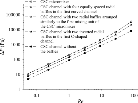
Figure 10 shows that the pressure applied increases with the increase of the number of the radial baffles. We refer to Lp=Li+Le+2θtRc+Lc+Lo as the overall channel length for comparison of the pressure applied between the inlets and the exit; Lp=4255 μm for the cases shown in Fig. 10. The driving pressure of the CSC channel with four equally spaced radial baffles is almost equal to that of the CSC micromixer, because they have the same passage width and the same number of baffles. However, the degree of mixing of the latter is greater than that of the former. Thus, the latter is superior to the former. The design of the CSC micromixer may be extended to a micromixer consisting of K mixing units and (K−1) straight channels.
Figure 10.
Pressures applied between the inlet and the outlet of the CSC micromixer (Rc=160 μm, Lp=4255 μm) and the other four micromixers (Rc=160 μm, Lp=4255 μm) for the cases with Re=0.054, 0.23, 1, 3, 9, 27, and 81.
To compare the CSC micromixer with radial baffles and the CSC channel without the baffles further, we consider the CSC micromixer shown in Fig. 1b and a CSC channel consisting of 25 C-shaped channels connected by 24 straight channels with Rc=160 μm and Lc=390 μm. For the case with Re=81, the latter can achieve the almost same degree of mixing (M≈93%) as that of the former at a higher pressure applied, ΔPCSC,25=35 944 Pa>ΔPCSC,baffle=33 799 Pa, while the channel length of the latter is 24 130 μm and that of the former is only 3605 μm. The present design (the CSC micromixer) can generate high mixing efficiency with a much shorter channel.
The above results show that the CSC micromixer is best used in the high Reynolds number region; an important addition to be made is the examination of the present design in the low Reynolds number region. For instance, at Re=0.054, the mixing efficiency based on the definition presented in Ref. 17 is 99%. The reason for considering this example is that the mixing efficiency of microchannels with rectangular ribs and wavy surface is available.17 Although there are a few percentages of computational errors or experimental errors, it can be seen that the mixing efficiency of the CSC micromixer is comparable with that of the T-shaped wavy microchannels with rectangular ribs.17 However, the length (Lm) of the CSC micromixer is only 3605 μm. From a further examination of the degree of mixing in the low Reynolds number region shown in Fig. 8, it can be seen that the degree of mixing increases with the decrease of the Reynolds number, and building radial baffles into the channel wall enhances fluid mixing even at a low Reynolds number. There are a number of reasons for the above results. One is that the small value of Reynolds number allows more time for mixing by pure diffusion. Another reason is that pure diffusion can be enhanced by increasing the interface between the two fluids and the radial baffles can bend and increase the area of the interface. Figure 8 also shows that the degree of mixing increases with the increase of the number of the radial baffles and the effect of the arrangement of the radial baffles on fluid mixing in the low Reynolds number region is not so important as that on fluid mixing in the high Reynolds number region.
CONCLUSIONS
In this work, we propose a high-efficiency planar micromixer constructed by building radial baffles into a curved microchannel with a small radius. The results show that the Dean vortices in the curved channel, the expansion vortices after the baffles, and the converging-diverging flow through the passages contribute together to the enhancement of fluid mixing. Besides, the arrangement of radial baffles has significant influence on the mixing efficiency. The basic C-shaped micromixer with the first baffle attached to the internal cylinder and the second attached to the external cylinder has better mixing as the Reynolds number is large enough. One of the reasons is that an extra vortex develops in the downstream of the second baffle of the basic C-shaped micromixer with a small enough radius. Furthermore, the basic C-shaped micromixer with two baffles of a distance db≈Wm can generate higher mixing efficiency. According to the trends found, we design a micromixer consisting of K basic C-shaped micromixers and (K−1) straight channels and show that the flow at the exit of the curved-straight-curved micromixer with K=2 can be considered as fully mixed (M>90%). The overall channel length of the curved-straight-curved micromixer with K=2 is relatively short, only 4255 μm. While the proposed micromixer is best used in the high Reynolds number region, building radial baffles into the curved channel wall also enhances fluid mixing even at a very small Reynolds number.
ACKNOWLEDGMENTS
We sincerely appreciate the support from the National Science Council of the Republic of China (NSC 94-2212-E-006-104 and NSC 95-2212-E-006-029). We also thank the Center for Micro∕Nano Science and Technology and the University Center for Bioscience and Biotechnology in National Cheng Kung University for the access of fabrication and experimental equipment.
References
- Tay F. E. H., Microfluidics and BioMEMS Applications (Kluwer, Boston, 2002). [Google Scholar]
- Liu L., Cao W., Wu J., Wen W., Chang D. C., and Sheng P., Biomicrofluidics 2, 034103 (2008). 10.1063/1.2966453 [DOI] [PMC free article] [PubMed] [Google Scholar]
- Atalay Y. T., Witters D. W., Vermeir S., Vergauwe N., Verboven P., Nicolaï B., and Lammertyn J., Biomicrofluidics 3, 044103 (2009). 10.1063/1.3250304 [DOI] [Google Scholar]
- Hessel V., Löwe H., and Schönfeld F., Chem. Eng. Sci. 60, 2479 (2005). 10.1016/j.ces.2004.11.033 [DOI] [Google Scholar]
- Nguyen N. T. and Wu Z., J. Micromech. Microeng. 15, R1 (2005). 10.1088/0960-1317/15/2/R01 [DOI] [Google Scholar]
- Liu R. H., Stremler M. A., Sharp K. V., Olsen M. G., Stantiago J. G., Adrian R. J., Aref H., and Beebe D. J., J. Microelectromech. Syst. 9, 190 (2000). 10.1109/84.846699 [DOI] [Google Scholar]
- Stroock A. D., Dertinger S. K. W., Ajdari A., Mezic I., Stone H. A., and Whitesides G. M., Science 295, 647 (2002). 10.1126/science.1066238 [DOI] [PubMed] [Google Scholar]
- Chen H. and Meiners J. -C., Appl. Phys. Lett. 84, 2193 (2004). 10.1063/1.1686895 [DOI] [Google Scholar]
- Bessoth F. G., deMello A. J., and Manz A., Anal. Commun. 36, 213 (1999). 10.1039/a902237f [DOI] [Google Scholar]
- Hessel V., Hardt S., Löwe H., and Schönfeld F., AIChE J. 49, 566 (2003). 10.1002/aic.690490304 [DOI] [Google Scholar]
- Knight J. B., Vishwanath A., Brody J. P., and Austin R. H., Phys. Rev. Lett. 80, 3863 (1998). 10.1103/PhysRevLett.80.3863 [DOI] [Google Scholar]
- Jiang F., Drese K. S., Hardt S., Küpper M., and Schönfeld F., AIChE J. 50, 2297 (2004). 10.1002/aic.10188 [DOI] [Google Scholar]
- Mengeaud V., Josserand J., and Girault H. H., Anal. Chem. 74, 4279 (2002). 10.1021/ac025642e [DOI] [PubMed] [Google Scholar]
- Wang H., Ioventitti P., Harvey E., and Masood S., Smart Mater. Struct. 11, 662 (2002). 10.1088/0964-1726/11/5/306 [DOI] [Google Scholar]
- Bhagat A. A. S., Peterson E. T. K., and Papautsky I., J. Micromech. Microeng. 17, 1017 (2007). 10.1088/0960-1317/17/5/023 [DOI] [Google Scholar]
- Chung C. K., Wu C. -Y., and Shih T. R., Microsyst. Technol. 14, 1317 (2008). 10.1007/s00542-007-0511-1 [DOI] [Google Scholar]
- Hsieh S. -S. and Huang Y. -C., J. Micromech. Microeng. 18, 065017 (2008). 10.1088/0960-1317/18/6/065017 [DOI] [Google Scholar]
- Tang K. C., Wibowo R. M., Ghista D. N., and Yobas L., Sens. Actuators B 128, 340 (2007). 10.1016/j.snb.2007.07.043 [DOI] [Google Scholar]
- Dean W. R., Philos. Mag. 4, 208 (1927). [Google Scholar]
- Rani S. A., Pitts B., and Stewart P. S., Antimicrob. Agents Chemother. 49, 728 (2005). 10.1128/AAC.49.2.728-732.2005 [DOI] [PMC free article] [PubMed] [Google Scholar]
- Boss J., Bulk Solids Handling 6, 1207 (1986). [Google Scholar]


