Abstract
This article covers several aspects of respiratory fluid mechanics that have been actively investigated by our group over the years. For the most part, the topics involve two-phase flows in the respiratory system with applications to normal and diseased lungs, as well as therapeutic interventions. Specifically, the topics include liquid plug flow in airways and at airway bifurcations as it relates to surfactant, drug, gene, or stem cell delivery into the lung; liquid plug rupture and its damaging effects on underlying airway epithelial cells as well as a source of crackling sounds in the lung; airway closure from “capillary-elastic instabilities,” as well as nonlinear stabilization from oscillatory core flow which we call the “oscillating butter knife;” liquid film, and surfactant dynamics in an oscillating alveolus and the steady streaming, and surfactant spreading on thin viscous films including our discovery of the Grotberg–Borgas–Gaver shock.
INTRODUCTION AND RESPIRATORY ANATOMY
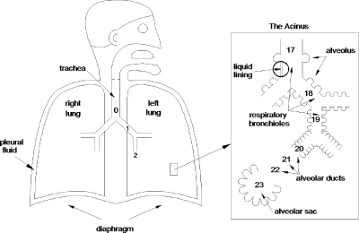
The respiratory system consists of two lungs, right and left, situated in the thorax and connected via their primary bronchi to the trachea and upper airway of the nose and mouth, see Fig. 1. The bronchi, or more generally the airways, then form a branching network which, for the most part, is a sequence of bifurcations. Each level of branching is called a generation, starting with the trachea as generation n=0, the primary bronchi, generation n=1, and so on. For a perfectly bifurcating system, there will be 2n airway tubes at generation n. For 0≤n≤16, the airways only conduct the gas flow in and out, they do not have any specialized apparatus for exchange of oxygen and carbon dioxide between air and blood. It is the conducting zone. For 17≤n≤19, there start to appear small air sacs, alveoli, on the airway walls. Alveoli are thin-walled and compliant with a rich capillary blood supply and are designed for gas exchange. These special airways are the respiratory bronchioles. For 20≤n≤22, the walls of the tubes or ducts are entirely made of alveoli, and then for n=23, there is the terminal alveolar sacs which are clusters of alveoli. From generations n=17 to the alveolar sacs is the respiratory zone.
Figure 1.
The respiratory system.
Just for comparison, the tracheal diameter is d0=1.8 cm in an adult, while the diameter of a terminal alveolus is ∼200–300 μm. The total cross-sectional area at the trachea is approximately , but the total surface area of all the 300×106 alveoli is 90 m2, similar to the surface area of a tennis court (singles). The enormous available surface area for gas exchange is far beyond what is essential for basic life, but gives great reserve for acute situations such as exercise or disease. For reasonable ventilation rates, the Reynolds number can range widely over the generations, thousands in the trachea, and much less than one in the alveoli.
The inside of the lung is coated with a liquid lining as indicated in Fig. 1. For the first 15 generations or so, the liquid lining consists of two layers. The serous layer is watery and adjacent to the airway wall which includes cilia that beat toward the mouth. The mucus layer is on top of the serous layer. Mucus has a number of non-Newtonian properties including viscoelasticity, shear thinning, and a yield stress. The serous fluid is essentially Newtonian.
The liquid layer is just the serous layer further out in the lung and the alveolar type II cells manufacture surfactants which orient at the air-liquid interface and reduce the surface tension significantly. Surfactants keep the lung compliant. Surfactant deficits or malfunction make the lung stiff and difficult to inflate.
CLINICAL APPLICATIONS
Surfactant replacement therapy
The airways convey ambient gas into and out of the lung for uptake of oxygen and removal of carbon dioxide. However, there are a number of situations in which liquid plugs form in an airway and block it from gas exchange. This can happen intrinsically: in normal subjects at full expiration in the lower lung, in diseases with excess liquid in the lungs (pulmonary edema, congestive heart failure, cystic fibrosis, asthma, emphysema). It can also occur from extrinsic factors: therapeutic liquid delivery into the lung as in surfactant replacement therapy,1 delivery of drugs,2, 3 genetic material,4, 5 stem cells,6, 7 liquid ventilation,8, 9 and drowning.
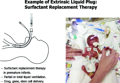
Surfactant replacement therapy is used for prematurely born infants who lack sufficient natural surfactant, so they have high surface tension in their lungs which are consequently mechanically stiff and difficult to ventilate, see Fig. 2. Prematurity of several weeks of course results in low birthweight as can be appreciated in the photo. Breathing is very difficult for these babies, and prior to the advent of surfactant replacement therapy, the mortality rate was sadly high. Figure 2 also shows the route of instilling a liquid bolus of commercial surfactant into the lungs via an endotracheal tube. While the replacement of surfactant by this method has decreased mortality by 30%–50%, the remaining 50%–70% do not survive. One of our goals has been to investigate and understand the fluid mechanics of this delivery process so improvements on delivery can be made.
Figure 2.
Surfactant replacement therapy in premature neonates.
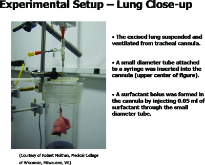
As part of the investigation, we collaborated with the physiologists to image the delivery of a liquid bolus into rat lungs. A typical lung is shown in Fig. 3.10 The lung is suspended by its tracheal connection to a ventilator and a liquid instillation system. The liquid surfactant (Survanta, Ross Laboratories, Columbus, OH) was instilled, with a small amount of radio-opaque marker, and its propagation while volume-cycling the lung is shown in Fig. 4 (video). The related video shows the plug formation and propagation to the distal airways. From the x-ray density distribution, it is possible to calculate the center of mass, and various moments, which fair well in comparison to plug propagation theory in a single tube.11 Plug formation during instillation of a liquid bolus into a tube has been studied in experiments12 and the distribution of the liquid bolus as it progressively coats the airways and splits at bifurcations has been studied in one-dimensional models.13, 14
Figure 3.
Excised rat lung experimental setup for imaging surfactant liquid plug transport as a model of SRT.
Figure 4.
Micro-CT of a surfactant liquid bolus delivered into the rat lung of Fig. 3 (enhanced online).
Liquid ventilation
Another approach to reducing the surface tension in these neonates has been to attempt ventilation by liquid rather than gas. The idea is to reduce the effects of surface tension by changing the air-liquid interface to a liquid-liquid interface. For liquid ventilation, a perfluorocarbon fluid, which can carry high amounts of oxygen and carbon dioxide, is used to cycle the lung instead of a gas. Some success in various animal models has been seen at this stage.15, 16, 17
Airway closure
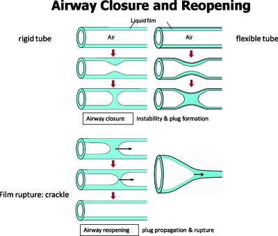
Another way for plugs to be in an airway is from the airway’s own liquid lining. When the lining layer is too thick, a Rayleigh instability can develop and create a plug18, 19, 20, 21 which closes the airway and stops gas exchange for that tube and all distal parts of the lung which are fed air flow by that tube. Figure 5 demonstrates this intrinsic liquid plug formation in a sequence of sketches. The insert video22 shows the closure process in a core-annular system with oil as the annular film and water as the core. The instability can be enhanced by flexibility of the airway wall which can partially collapse, giving a capillary-elastic instability as shown in sequence.23, 24
Figure 5.
Intrinsic liquid plug formed from capillary, or capillary-elastic, instability.
Airway reopening
To reopen the airway, airflow (say during inspiration) transports the plug and if the precursor liquid film is thinner than the trailing film, the plug’s volume decreases until it ruptures, thus reopening the airway for gas exchange. It is thought that this rupture process causes an acoustical signal called a “crackle,” which can be heard by stethoscope placed on the chest wall near enough to the source. Inspiratory crackles are the hallmark of diseases which increase the presence of liquid in airways and alveoli (e.g., congestive heart failure, pulmonary edema, pneumonia, bronchitis, asthma, emphysema, cystic fibrosis). If the airway is flexible enough, a “peeling open” process can occur as shown.25
LIQUID PLUG PROPAGATION
Steady plug propagation in a flexible tube
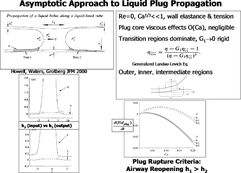
Common to all of the above examples of liquid plugs in airways is their propagation due to air flow. Figure 6 is a selection of results from an asymptotic solution for liquid plug propagation in a flexible tube,26 which can be considered as either a liquid delivery or airway reopening application. The assumptions of Re=0 and Ca1∕3⪡1 lead to an O(Ca) viscous problem in the plug core which can be ignored. So the plug has a constant plug core pressure, and flow resistance is dominated by the transition regions, at O(Ca1∕3) which join the plug core to the precursor and trailing films. A generalized Landau–Levich equation is found with new information about the wall elasticity. Interestingly, in the limit of high longitudinal wall tension, competing length scales of the wall and the air-liquid interface create a double boundary layer in the axial direction with outer, intermediate (wall tension dominated), and inner (surface tension dominated) regions.
Figure 6.
Asymptotic solution of a liquid plug propagating in a flexible tube. Upper left: problem sketch and definitions; upper right: generalized Landau–Levich equation and asymptotic boundary layer regions; lower left: wall and interface positions for precursor film thickness h2>trailing film thickness h1 and h2<h1; lower right: time rate of plug volume change for three values of Γ as a function of the capillary number, Ca. Reprinted with permission P. D. Howell, S. L. Waters, and J. B. Grotberg, J. Fluid Mech. 406, 309 (2000). Copyright ©2000, Cambridge University Press.
Steady plug propagation and effects of surfactant
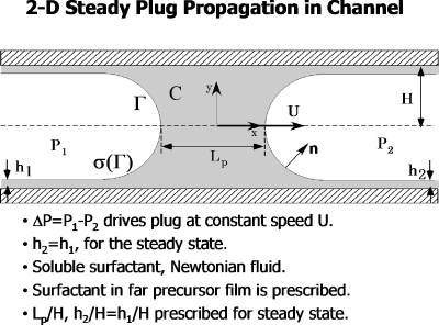
Figure 7 is a schematic of a liquid plug in a two-dimensional channel propagating at speed U due to the driving pressure P1−P2. The fluid is Newtonian and contains a soluble surfactant whose bulk concentration is C and surface concentration is Γ. The local surface tension depends on the surface concentration of surfactant, σ=σ(Γ). This model assumes steady flow, so h1=h2.
Figure 7.
Steady 2D plug propagation in a channel, showing definitions and problem assumptions. Reprinted with permission from H. Fujioka and J. B. Grotberg, Phys. Fluids 17, 082102 (2005). Copyright 2005, American Institute of Physics.
Numerical solutions for this problem were presented in Ref. 27 by solving the continuity and steady Navier–Stokes equations, along with conservation of C and Γ, and the interfacial (adsorption-desorption) kinetics between them. The kinematic boundary conditions on the wall and interface, as well as the normal and tangential stress boundary conditions at the interface, must also be satisfied. Using a nonlinear (modified Frumkin) equation of state σ(Γ) between the surface tension and the surface leads to a sample solution of the pressure and velocity fields, as well as the surfactant concentration field shown in Fig. 8. The important dimensionless groups are the Reynolds number, Re=ρUH∕μ, and the capillary number, Ca=μU∕σm, where σm is the surfactant-free surface tension. In order to express the plug speed in only one of these, an equivalent pair of parameters is Re and λ=Re∕Ca=ρHσm∕μ2. From the surfactant conservation equations there are the bulk and surface Peclet numbers, and from the equation of state we have the surface elasticity parameter E=−(Γ∞∕σm)(∂σ∕∂Γ) which reflects the Marangoni number Ma=E∕Ca.
Figure 8.
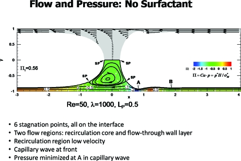
Steady plug propagation with no surfactant. Reprinted with permission from H. Fujioka and J. B. Grotberg, Phys. Fluids 17, 082102 (2005). Copyright 2005, American Institute of Physics.
Figure 8 from Ref. 27 shows the plug propagation in the frame of the plug, so the wall is traveling to the left at dimensionless speed of −1. This example has Re=50, λ=1000 and the plug length scaled on H is LP=0.5. The lower half of the figure shows the streamlines and pressure field, while the symmetric upper half shows velocity vectors. Note that there are two distinct flow regions in the lower half: the wall layer and the plug core vortex. Six stagnation points arise, all on the interface, with two at the midline, two in the lower half and two in the upper half of the plug. The precursor film has a capillary wave with a minimum thickness just in front of the core denoted by A, where wall shear stress becomes maximal.
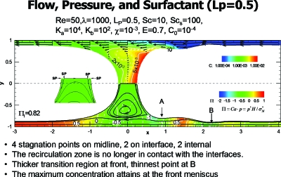
Plug propagation with surfactant is shown in Fig. 9 from Ref. 27. For E=0.7 and the remaining parameter values as indicated, there are significant differences from Fig. 8. The six stagnation points have become four, and are all on the midline, with two in the interface and the other two internal, see insert. Consistent with this change is that the surface velocities at the front and rear of the plug core are reversed from the no-surfactant case, driven now by surface tension gradients. The film thickness at point A is much thicker, thus reducing the shear stress on the wall there. The surfactant concentration is shown in the upper half and reveals the buildup of surfactant in the front of the plug. Additional work in this area for long bubbles has been done by others.28, 29
Figure 9.
Steady plug propagation with surfactant. Reprinted with permission from H. Fujioka and J. B. Grotberg, Phys. Fluids 17, 082102 (2005). Copyright 2005, American Institute of Physics.
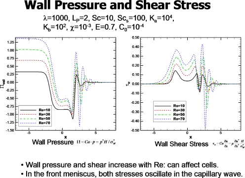
The fluid stresses on the walls can influence the airway epithelial cells by provoking the release of bioactive molecules as well as injuring them. Figure 10 from Ref. 27 shows the distribution of wall pressure and shear stress for the steady plug at different values of Re. The plug length is LP=2, so the front of the plug at the midline, y=0, is at x=1 and the rear at x=−1. The pressures and shear stresses increase with increasing Re. The region in front of the plug sees the largest shear stress and the most negative pressure, as well as experiencing the largest axial gradients of pressure and shear stress. There are a number of industrial applications of liquid plug propagation including oil recovery technology, hazardous waste removal, and microchannel reactors.30, 31, 32
Figure 10.
Wall pressure and shear stress for different Re. Reprinted with permission from H. Fujioka and J. B. Grotberg, Phys. Fluids 17, 082102 (2005). Copyright 2005, American Institute of Physics.
Steady plug propagation and effects of gravity
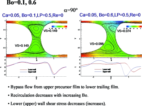
Figure 11 shows results of a computational study of liquid plug propagation in a channel with the effects of gravity.33 For the Bond number, Bo=0.1, fluid from the upper precursor film near the interface is entrained by the upper vortex, then handed off to the entrained flow of the lower vortex, and then into the lower trailing film. This process is more evident for Bo=0.6, where the vortices are smaller and the relative thickening of the lower trailing film more prominent.
Figure 11.
Gravity effects on plug propagation. Reprinted with permission from Y. Zheng, H. Fujioka, and J. B. Grotberg, Phys. Fluids 19, 082107 (2007). Copyright 2007, American Institute of Physics.
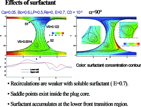
Figure 12 from Ref. 33 shows the effects of surfactant on the plug of Fig. 11. Note the bounding streamlines of the vortices form saddle points, and there is accumulation of surfactant at the lower front interface. The recirculation is weaker in the vortices.
Figure 12.
Surfactant effects on plug propagation with gravity. Reprinted with permission from Y. Zheng, H. Fujioka, and J. B. Grotberg, Phys. Fluids 19, 082107 (2007). Copyright 2007, American Institute of Physics.
Unsteady plug propagation
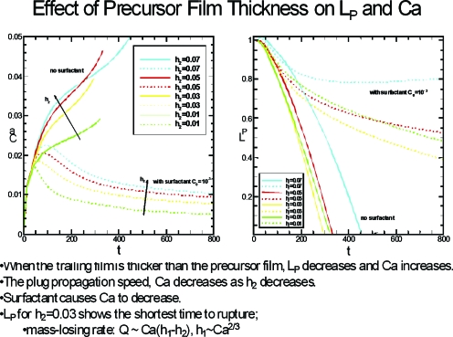
Figure 13 shows the results of unsteady plug propagation based on the computations found in Ref. 34. At t=0 the plug is exposed to a dimensionless unit pressure drop P1−P2=1. The left frame is the plug speed, Ca, while the right frame is the plug length LP. Two sets of results are in each graph, plugs with no surfactant and plugs with surfactant, and within those two groups are several values of the precursor thickness h2. The plug ruptures when LP goes to zero, which occurs for all nonsurfactant plugs in this set of results. When surfactant is present, the plug can reach an essentially constant length as time increases. So a strategy may be available to deliver the plug contents farther downstream if surfactants are used by avoiding rupture. If a plug contains transportable materials that are targeted to the airways, then it would be beneficial to have the rupture occur just downstream of those airways so the largest possible dose goes to them. Examples could be delivery of antibiotics, genetic material, or even stem cells. If the target is the alveoli, as is common for surfactant delivery, then it is better to avoid rupture and have the contents reach the alveoli as much intact and undiluted as possible.
Figure 13.
Time-dependence of the plug speed (Ca) and plug length LP for different values of the precursor film thickness h2. Reprinted with permission from H. Fujioka, S. Takayama, and J. B. Grotberg, Phys. Fluids 20, 062104 (2008). Copyright 2008, American Institute of Physics.
Effects on epithelial cells: Airway on a chip
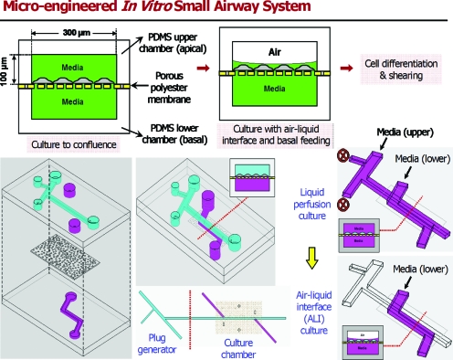
When a liquid plug is close to depositing all of its volume into the trailing film, the plug becomes so thin at its midline that it will rupture. In the lung, this event can create a sound called a respiratory crackle which is heard with a stethoscope. Clinically it can be an indication of pulmonary edema or other fluid buildups such as pneumonia or an excess of mucus (asthma, emphysema, cystic fibrosis). In addition to being a clinical sign, however, is the plug rupture process also injurious to the lung? This question was studied in Ref. 35 by a microfluidic system shown in Fig. 14. Human pulmonary airway epithelial cells were grown on a membrane with an underlying media bath and an overlying liquid film, i.e., an airway on a chip.36 Liquid plugs were propagated over the cells and then the cells were stained to look for damage.
Figure 14.
Microfluidics system for exposing human pulmonary airway epithelial cells to liquid plugs. Reprinted with permission from D. Huh, H. Fujioka, Y. C. Tung, N. Futai, R. Paine, J. B. Grotberg, and S. Takayama, Proc. Natl. Acad. Sci. U.S.A. 104, 18886 (2007). Copyright 2007, National Academy of Sciences, U.S.A.
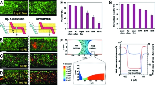
Figure 15 shows the stained cells: green are healthy and red cells are dead. The protocol called for 5 or 10 plugs∕min for 10 min. The passage of the plugs over cells is clearly damaging, as the red count is evident at stations B, C, and D. However, the plugs ruptured at station A, and there the rupture causes a significant increase in cell death. This is the first understanding in the field of respiratory medicine that the crackle sounds heard so routinely by physicians are also a potential source of injury. Fundamental fluid mechanics has been an important means of revealing this connection.
Figure 15.
Results of plug passages and ruptures over the airway cells. Red cells are dead and green are alive. (a) Single-phase liquid flows do not damage differentiated cells. Exposure to propagation and subsequent rupture of liquid plugs results in progressively larger numbers of injured cells [(b)–(d)]. PR is plug propagation and ruptures within 10 min. (e) The extent of cellular damage is elevated with increasing PR. (f) Numerical simulation reveals generated large wall shear and wall pressure gradients. (g) Downstream viability suggests more deleterious mechanical stresses at site of plug rupture. Reprinted with permission from D. Huh, H. Fujioka, Y. C. Tung, N. Futai, R. Paine, J. B. Grotberg, and S. Takayama, Proc. Natl. Acad. Sci. U.S.A. 104, 18886 (2007). Copyright 2007, National Academy of Sciences, U.S.A.
LIQUID PLUG SPLITTING
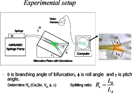
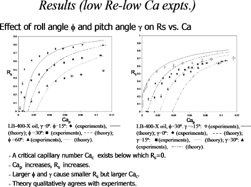
When the plug reaches an airway bifurcation, it will split in some ratio depending on the physical features of the flow. Then it will split at successive airway generations, so that understanding the split phenomena will shed light on what determines the final distribution of the plug. A split ratio of unity at each bifurcation would lead to a homogeneous distribution, for example. Other values will leave the distribution non-homogeneous. Gravity effects are important for this split in the larger airways where the Bond number is appreciable. Figure 16 shows an experimental apparatus from the work in Refs. 37, 38 used to measure the split ratio RS defined as the plug volume going uphill divided by the volume going downhill. This keeps 0≤RS≤1 as a function of the initial plug capillary number, the Bond number, the initial plug volume, and the roll and pitch angles, ϕ and γ, respectively.
Figure 16.
Experimental setup for gravity effects on plug splitting. Reprinted with permission from Y. Zheng, J. C. Anderson, V. Suresh, and J. B. Grotberg, J. Biomech. Eng. 127, 798 (2005); 128, 707 (2006). Copyright 2005, 2006, The American Society of Mechanical Engineers (ASME).
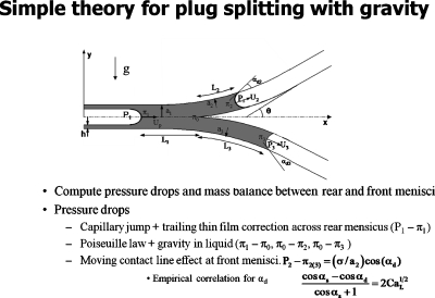
Figure 17 shows the problem formulation for a simple theory of plug splitting.37 The law of Laplace is used for the pressure jump across the interfaces, Poiseuille Law is used for the viscous pressure drop from the rear interface to the bifurcation, and then again from the bifurcation to each of the two front interfaces while incorporating gravity. For a tube experiment, there is no precursor film so an extra pressure drop due to the moving contact line is included.39
Figure 17.
Simple theory of plug splitting. Reprinted with permission from Y. Zheng, J. C. Anderson, V. Suresh, and J. B. Grotberg, J. Biomech. Eng. 127, 798 (2005); 128, 707 (2006). Copyright 2005, 2006, The American Society of Mechanical Engineers (ASME).
Figure 18 shows the results of the experiments and theory by plotting split ratio RS versus the capillary number Cap of the plug when it starts in the parent tube, for different roll angles.37 The theory captures the important qualitative features of the data that increasing Cap increases RS toward unity with an asymptote which decreases as the roll angle increases. Also, there is a critical value of Cap below which RS=0, i.e., the plug goes completely downhill when its speed is low enough. That means the pressure at the bifurcation must be high enough to overcome gravity and push fluid uphill.
Figure 18.
Results of experiments and theory for plug splitting. Reprinted with permission from Y. Zheng, J. C. Anderson, V. Suresh, and J. B. Grotberg, J. Biomech. Eng. 127, 798 (2005). Copyright 2005, The American Society of Mechanical Engineers (ASME).
SURFACTANT SPREADING ON THIN FILMS AND THE “GROTBERG–BORGAS–GAVER (GBG) SHOCK”
Delivery of surfactant into the lung involves the plug convection process discussed above, but also at a smaller scale level there eventually will be a surfactant layer spreading on a thin viscous liquid layer. Initial interest in this topic for our laboratory came through General Motors Corporation. They were concerned about respiratory aerosols that arise in manufacturing, namely, oil fogs. High rotational speed drills, which are coated with oil for lubrication, spin off oil droplets that can be inhaled by workers. What happens when that oil droplet encounters the air-liquid interface of the airway liquid lining? Likewise, aerosolized surfactants were being investigated for delivery into neonates and adults by a number of pulmonary researchers at that time. What happens when a surfactant droplet hits the interface? This is the “business end” of aerosol delivery, and a naked research area in those days but now is being considered in the design of medical aerosols.40
Once a droplet hits the interface (or a spreading surfactant front arrives), then the Marangoni effect of a surface tension gradient induced flow can cause it to spread along the interface. For a thin viscous film, we have shown41, 42, 43 that the spreading becomes a kinematic shock wave. Figure 19 shows a steady flow model41 that we solved with a lower wall moving to the right at unit speed. The air-liquid interface to the left is clean, with no surfactant, and to the right it is a monolayer which is restrained by a barrier. In the limit of both lubrication theory and negligible surface diffusion, there is a steady solution to the governing equations which has a jump in surface height from H=1 to H=2 which satisfies conservation of mass, since the oncoming flow is a flat profile under the clean interface and a linear profile under the stationary surfactant interface.
Figure 19.
Steady surfactant spreading as a standing GBG shock wave. Reprinted with permission from M. S. Borgas and J. B. Grotberg, J. Fluid Mech. 193, 151 (1988). Copyright 1988, Cambridge University Press.
Unsteady surfactant spreading42, 43 shown in Fig. 20 is also for an insoluble surfactant monolayer. At t=0 the surfactant concentration, Γ(r,0), is uniformly distributed for 0≤r≤RI<1 and fitted to a cosine function for RI≤r≤1, such that ∂Γ∕∂r=0 at r=RI and 1. A typical value chosen for RI is 0.7. Also at t=0 the interfacial height is given as H=1. These are the initial conditions for the coupled partial differential equations (PDEs) shown in the upper left, which are derived from the conservation laws and boundary conditions. The upper right graphs show the interface position and surfactant distribution at four values of time as the surfactant spreads. As time increases, the height of the interface is approaching 2 as would happen in the steady case shown in Fig. 19. Also, the minimum height is just behind the shock. The lower left shows that the shock speed is equal to the ratio of the jump in volume flow to the jump in cross-sectional area of the film, consistent with the definition of a kinematic shock wave.
Figure 20.
Unsteady surfactant spreading with GBG shock evolution. Reprinted with permission from D. P. Gaver and J. B. Grotberg, J. Fluid Mech. 213, 127 (1990). Copyright 1990, Cambridge University Press.
Experiments confirmed the spreading computations and development of the shock,43 while additional theory and experiments considered pre-existing surfactant on the surface, stretching wall motion, and finite boundaries for the interface.13, 44, 45, 46, 47, 48 A movie of this type of flow is shown in Fig. 21, which is the first frame. The view is from above over a thin viscous film which is contained in a trough. The liquid surface is sprinkled with talc for visualization and there are red dye streaks along the bottom of the trough at the liquid-trough wall interface. For this choice of initial film thickness, as the surfactant drop spreads radially outward, it drags the fluid with it and the minimum height just behind the shock front leads to film rupture resulting in a dry ring with an interruption of the dye streaks. Spreading stops rupture of the liquid layer, so would be an unwanted result if the desire is to have the surfactant spread as far as possible. For thicker films, not shown, the shock elevates the fluid in front of it enough to cause gravity effects to drive the fluid near the wall radially inward from hydrostatic pressure, giving a bidirectional flow.42, 43 Additional work on the shock wave from our group,49, 50 and subsequently from many others, have all shown it to be rich in fluid dynamics. Applications include fingering instabilities,51 precorneal tear film dynamics,52 analysis of wave propagation,53, 54 wine tears,55 drying instabilities,56 and the spreading of bacteria.57 Dr. Borgas, Dr. Gaver and I felt that, after over 20 years, we should name the shock and that this article was an appropriate vehicle to do so.
Figure 21.
Movie of surfactant drop spreading on the surface of a thin viscous film revealing critical thinning and film rupture behind the GBG shock (enhanced online).
ALVEOLAR LIQUID FILM DYNAMICS
A simplified model of an alveolus is shown in Fig. 22 from the analysis presented in Ref. 58. The two-dimensional alveolus is assumed to be a circular cap with an opening width a(t)=a0[1+Δf(t)], where a0 is the mean opening width, a0Δ is the breathing amplitude, and f(t) is a time-dependent function prescribed for breathing. The system requires conservation of bulk surfactant, conservation of interfacial surfactant, normal (capillarity) and tangential (Marangoni) stress boundary conditions at the interface. For fast bulk diffusion the bulk concentration is essentially constant, C=1. Assuming the surface tension is high enough, the interface maintains a circular shape and then it is convenient to use bipolar coordinates. Both the Bond number and Reynolds number are negligible since the alveolar radius is so small (∼150 μm). The remaining control parameter is taken to be dimensionless sorption, K=a0kd∕U, where kd is the dimensional sorption constant, a0 is the alveolar radius, and U is the velocity scale from the oscillation. The combination of these forces results in a competition of mechanisms that can induce flow: wall motion, capillarity, and surface tension gradients. Under normal circumstances, the liquid layer is thin and we investigated a thin layer model in our previous work.59 The problem shown in Fig. 22 can have a thick layer and represents the situation in many diseases which lead to a liquid excess in the alveoli: congestive heart failure, pulmonary edema, and acute respiratory distress syndrome. The latter can result from many kinds of medical insults: surfactant deficiency, infections in the bloodstream, pneumonia, severe bleeding, trauma, toxic fumes, and aspiration.
Figure 22.
Model of an oscillating alveolus with a liquid film. Reprinted with permission from H. H. Wei, H. Fujioka, R. B. Hirschl, and J. B. Grotberg, Phys. Fluids 17, 031510 (2005). Copyright 2005, American Institute of Physics.
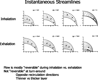
Typical streamlines are shown in Fig. 23. During either inspiration or expiration, there is outward or inward flow, respectively. However, at the turnaround the velocity field is vortical with the direction of the vortex flow either clockwise or counterclockwise.
Figure 23.
Instantaneous streamlines at several phases of the alveolar oscillation. Reprinted with permission from H. H. Wei, H. Fujioka, R. B. Hirschl, and J. B. Grotberg, Phys. Fluids 17, 031510 (2005). Copyright 2005, American Institute of Physics.
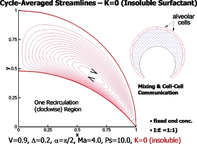
The type of flow pattern led us to inquire about the possibility of communication among the alveolar cells with the alveolar fluid as the conveying medium. It has always been assumed that the blood flow, lymphatic flow, or interstitial flow provides the vehicle for communication. So our investigation presents a novel idea for lung physiology. Time-averaging the velocities gave us the cycle-averaged streamlines as shown in Fig. 24 for an insoluble surfactant (K=0). The vortex is clockwise and can provide a steady convective field for the transport of signaling molecules secreted by alveolar cells.
Figure 24.
Cycle-averaged streamlines showing one vortex for K=0, insoluble surfactant. Reprinted with permission from H. H. Wei, H. Fujioka, R. B. Hirschl, and J. B. Grotberg, Phys. Fluids 17, 031510 (2005). Copyright 2005, American Institute of Physics.
The sorption parameter is significant. A sequence of figures showing steady streamlines for three nonzero values of K is shown in Fig. 25. From left to right we see the development of two vortices, three vortices, and a saddle point.
Figure 25.
[(a)–(c)] Cycle-averaged streamlines for three values of the sorption parameter K as shown. Reprinted with permission from H. H. Wei, H. Fujioka, R. B. Hirschl, and J. B. Grotberg, Phys. Fluids 17, 031510 (2005). Copyright 2005, American Institute of Physics.
AIRWAY CLOSURE
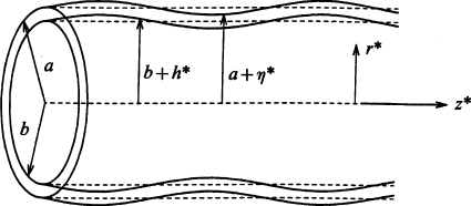
Airways are liquid lined, flexible tubes as shown in Fig. 26,23 where the unperturbed tube radius is a and the unperturbed film thickness is (a−b). The ratio of the liquid film thickness to the tube radius is ε=(a−b)∕a. The air-liquid interface is subject to Rayleigh instabilities, and if ε is large enough, say ε>εc, the instability has enough liquid to create a plug which occupies the entire tube cross section. This phenomenon is known as airway closure in the lung setting, and it can be enhanced by the flexibility of the tube. Airway closure occurs in normal individuals near the end of expiration, usually only in small airways and those that are in the lower (gravity-dependent) lung regions since those airway radii are still smaller due to the weight of the lung above. Because the closed airway does not allow gas exchange distally, the region of the lung normally ventilated through that airway is no longer ventilated. This leads to an inhomogeneity of gas exchange and a mismatch of ventilation with blood perfusion. From the discussion above of airway reopening, it takes the next inspiration to propagate the plug and rupture it to re-establish ventilatory gas flow. Because of the gravity influence, the majority of the lung above does not experience closure under normal circumstances. The lung volume at which closure initiates is known pulmonary physiology as the “closing volume.” Closing volumes vary with disease, age, pregnancy, and other clinical settings. A potential respiratory issue for breathing in microgravity environments is that airway closure, if it occurs, would not have a preference for any lung region so could occur everywhere. For situations in which the plug does not rupture, that portion of the lung can be blocked from gas ventilation and eventually its resident gas will absorb into the capillary blood and the region collapses, a condition known as atelectasis. A new finding from combined experimental and theoretical studies60 indicates that fluid shear stresses on the wall during airway closure can be just as large, if not larger, than those that occur during airway reopening. So mechanical damage to the airway epithelial cells can occur during both phases, closure and reopening.
Figure 26.
Liquid lined flexible tube with an initial sinusoidal perturbation of the air-liquid and liquid-wall interfaces.
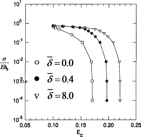
In Ref. 24 we investigated the critical ratio of the liquid film thickness to tube radius εc and its dependence on airway flexibility and surfactant activity. The Rayleigh instability in the setting of a flexible tube is a novel mechanical system which we call a “capillary-elastic instability.” A new parameter arises to describe the relative balance of surface tension and tube elasticity, σ∕Eh0, where h0 is the tube wall thickness, σ is the surface tension, and E is the elastic modulus for the tube material. In Fig. 27 the results are shown for varying σ∕Eh0 and the surfactant activity . For a rigid tube, σ∕Eh0→0 and a clean interface with no surfactants, , the critical liquid film thickness was found to be εc∼0.17. Increasing the surfactant strength to increases εc, so surfactants stabilize airways from closing since the airway can stay open with a thicker film. For a given surfactant activity level, making the wall more flexible relative to the surface tension, σ∕Eh0 increasing, lowers εc making the system less stable. It is the air-liquid interfacial curvature in the transverse (z=constant) plane which is the destabilizing contribution to the Rayleigh instability. The inward radial deflection of the flexible tube causes that transverse curvature to increase, forcing the system to be less stable.
Figure 27.
Critical liquid film thickness εc vs σ∕Eh0 for three values of surfactant activity .
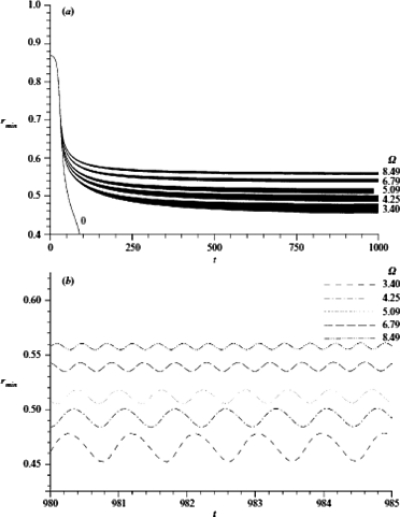
Since the core fluid of Fig. 26 is the gas which oscillates into and out of the lung, we wondered if a cycling frequency and amplitude could be found to prevent airway closure, and, if so, by what mechanism.61 Under reasonable assumptions the oscillatory gas flow can drive the liquid film and be considered uncoupled, so the film motion does not affect the gas oscillation. For a thick enough film, the Rayleigh instability initiates wave growth so that the minimum radius of the interface location, rmin(t), decreases on the average, while also responding to the time-periodic core flow stress, see Fig. 28. If the frequency and amplitude are too small, then the airway closes. However, if the frequency and amplitude are high enough, they cause the time-averaged rmin to oscillate around a nonzero value, i.e., the tube remains open. Figure 28 shows that the average value of rmin increases with frequency, while the amplitude of the rmin oscillation decreases with frequency.
Figure 28.
The effect of frequency on the minimum core radius rmin(t) with time t. Here, β=43.05, ε=0.13, γ=0.0018 and λ=14.86. Reprinted with permission from D. Halpern and J. B. Grotberg, J. Fluid Mech. 492, 251 (2003). Copyright 2003, Cambridge University Press.
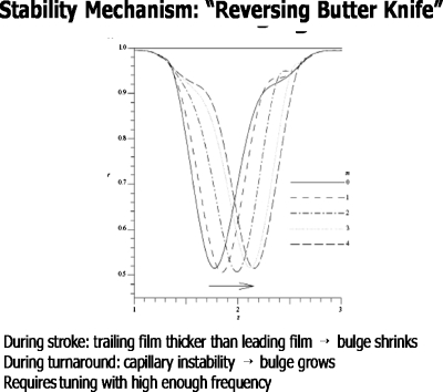
The mechanism is shown in Fig. 29.61 During the power stroke the leading film is thicker than the trailing film and the fluid bulge diminishes, much like the process for liquid plug flow discussed above. During the turnaround phase, however, the fluid velocities are smaller and the capillary instability dominates, so the bulge grows. With the right tuning of frequency and amplitude, the two phases combine to reach an average rmin>0, keeping the tube open. We call this the “oscillating butter knife” mechanism. The liquid film is rhythmically reapplied to the wall, just tuned to balance the closure process. Figure 30 is a simulation of this process from solutions of the governing equations.
Figure 29.
“Reversing butter knife” stability mechanism responsible for the nonlinear saturation of the Rayleigh instability. Reprinted with permission from D. Halpern and J. B. Grotberg, J. Fluid Mech. 492, 251 (2003). Copyright 2003, Cambridge University Press.
Figure 30.
Video of oscillatory flow imposed during a closure instability. Nonlinear saturation prevents closure by the reversing butter knife mechanism (enhanced online).
ACKNOWLEDGMENTS
This work supported by NIH Grant Nos. HL85156 and HL84370.
We are grateful to the Journal of Fluid Mechanics for permission to reprint Figs. 31–35 and to the Proceedings of the National Academy of Sciences for permission to reprint Figs. 36 and 37.
References
- Stevens T. P. and Sinkin R. A., “Surfactant replacement therapy,” Chest 131, 1577 (2007). 10.1378/chest.06-2371 [DOI] [PubMed] [Google Scholar]
- van’t Veen A., Wollmer P., Nilsson L. E., Gommers D., Mouton J. W., Kooij P. P. M., and Lachmann B., “Lung distribution of intratracheally instilled Tc-99m-tobramycin-surfactant mixture in rats with a Klebsiella pneumoniae lung infection,” Appl. Cardiopulm. Pathophysiol. 7, 87 (1998). [Google Scholar]
- Nimmo A. J., Carstairs J. R., Patole S. K., Whitehall J., Davidson K., and Vink R., “Intratracheal administration of glucocorticoids using surfactant as a vehicle,” Clin. Exp. Pharmacol. Physiol. 29, 661 (2002). 10.1046/j.1440-1681.2002.03712.x [DOI] [PubMed] [Google Scholar]
- Raczka E., Kukowska-Latallo J. F., Rymaszewski M., Chen C., and J. R.Baker, Jr., “The effect of synthetic surfactant Exosurf on gene transfer in mouse lung in vivo,” Gene Ther. 5, 1333 (1998). 10.1038/sj.gt.3300752 [DOI] [PubMed] [Google Scholar]
- Manuel S. M., Guo Y., and Matalon S., “Exosurf enhances adenovirus-mediated gene transfer to alveolar type II cells,” Am. J. Physiol. Lung Cell. Mol. Physiol. 17, L741 (1997). [DOI] [PubMed] [Google Scholar]
- Leblond A. -L., Naud P., Forest V., Gourden C., Sagan C., Romefort B., Mathieu E., Delorme B., Collin C., Pages J. -C., Sensebe L., Pitard B., and Lemarchand P., “Developing cell therapy techniques for respiratory disease: Intratracheal delivery of genetically engineered stem cells in a murine model of airway injury,” Hum. Gene Ther. 20, 1329 (2009). 10.1089/hum.2009.035 [DOI] [PMC free article] [PubMed] [Google Scholar]
- van Haaften T., Byrne R., Bonnet S., Rochefort G. Y., Akabutu J., Bouchentouf M., Rey-Parra G. J., Galipeau J., Haromy A., Eaton F., Chen M., Hashimoto K., Abley D., Korbutt G., Archer S. L., and Thebaud B., “Airway delivery of mesenchymal stem cells prevents arrested alveolar growth in neonatal lung injury in rats,” Am. J. Respir. Crit. Care Med. 180, 1131 (2009). 10.1164/rccm.200902-0179OC [DOI] [PMC free article] [PubMed] [Google Scholar]
- Hirschl R. B., Croce M., Gore D., Wiedemann H., Davis K., Zwischenberger J., and Bartlett R. H., “Prospective, randomized, controlled pilot study of partial liquid ventilation in adult acute respiratory distress syndrome,” Am. J. Respir. Crit. Care Med. 165, 781 (2002). [DOI] [PubMed] [Google Scholar]
- Hirschl R. B., Conrad S., Kaiser R., Zwischenberger J. B., Bartlett R. H., Booth F., and Cardenas V., “Partial liquid ventilation in adult patients with ards: A multicenter phase i-ii trial. Adult PLV study Group,” Ann. Surg. 228, 692 (1998). 10.1097/00000658-199811000-00009 [DOI] [PMC free article] [PubMed] [Google Scholar]
- Anderson J. C., Molthen R. C., Dawson C. A., Haworth S. T., Bull J. L., Glucksberg M. R., and Grotberg J. B., “Effect of ventilation rate on instilled surfactant distribution in the pulmonary airways of rats,” J. Appl. Physiol. 97, 45 (2004). 10.1152/japplphysiol.00609.2003 [DOI] [PubMed] [Google Scholar]
- Cassidy K. J., Bull J. L., Glucksberg M. R., Dawson C. A., Haworth S. T., Hirschl R. B., Gavriely N., and Grotberg J. B., “A rat lung model of instilled liquid transport in the pulmonary airways,” J. Appl. Physiol. 90, 1955 (2001). 10.1063/1.1381556 [DOI] [PubMed] [Google Scholar]
- Espinosa F. F. and Kamm R. D., “Meniscus formation during tracheal instillation of surfactant,” J. Appl. Physiol. 85, 266 (1998). [DOI] [PubMed] [Google Scholar]
- Halpern D., Jensen O. E., and Grotberg J. B., “A theoretical study of surfactant and liquid delivery into the lung,” J. Appl. Physiol. 85, 333 (1998). [DOI] [PubMed] [Google Scholar]
- Espinosa F. F. and Kamm R. D., “Bolus dispersal through the lungs in surfactant replacement therapy,” J. Appl. Physiol. 86, 391 (1999). [DOI] [PubMed] [Google Scholar]
- Shaffer T. H., Wolfson M. R., and Clark L. C., “Liquid ventilation,” Pediatr. Pulmonol. 14, 102 (1992). 10.1002/ppul.1950140208 [DOI] [PubMed] [Google Scholar]
- Hirschl R. B., Parent A., Tooley R., McCracken M., Johnson K., Shaffer T. H., Wolfson M. R., and Bartlett R. H., “Liquid ventilation improves pulmonary function, gas exchange, and lung injury in a model of respiratory failure,” Ann. Surg. 221, 79 (1995). 10.1097/00000658-199501000-00010 [DOI] [PMC free article] [PubMed] [Google Scholar]
- Bull J. L., Tredici S., Fujioka H., Komori E., Grotberg J. B., and Hirschl R. B., “Effects of respiratory rate and tidal volume on gas exchange in total liquid ventilation,” ASAIO J. 55, 373 (2009). 10.1097/MAT.0b013e3181a793b5 [DOI] [PubMed] [Google Scholar]
- Everett D. H. and Haynes J. M., “Model studies of capillary condensation 1. Cylindrical pore model with zero contact angle,” J. Colloid Interface Sci. 38, 125 (1972). 10.1016/0021-9797(72)90228-7 [DOI] [Google Scholar]
- Kamm R. D. and Schroter R. C., “Is airway closure caused by a thin liquid instability?” Respir. Physiol. 75, 141 (1989). 10.1016/0034-5687(89)90059-5 [DOI] [PubMed] [Google Scholar]
- Johnson M., Kamm R. D., Ho L. W., Shapiro A., and Pedley T. J., “The nonlinear growth of surface-tension-driven instabilities of a thin annular film,” J. Fluid Mech. 233, 141 (1991). 10.1017/S0022112091000423 [DOI] [Google Scholar]
- Campana D., Di Paolo J., and Saita F. A., “A 2-D model of Rayleigh instability in capillary tubes - surfactant effects,” Int. J. Multiphase Flow 30, 431 (2004). 10.1016/j.ijmultiphaseflow.2004.03.007 [DOI] [Google Scholar]
- Cassidy K. J., Halpern D., Ressler B. G., and Grotberg J. B., “Surfactant effects in model airway closure experiments,” J. Appl. Physiol. 87, 415 (1999). [DOI] [PubMed] [Google Scholar]
- Halpern D. and Grotberg J. B., “Fluid-elastic instabilities of liquid-lined flexible tubes,” J. Fluid Mech. 244, 615 (1992). 10.1017/S0022112092003227 [DOI] [PubMed] [Google Scholar]
- Halpern D. and Grotberg J. B., “Surfactant effects on fluid-elastic instabilities of liquid-lined flexible tubes: A model of airway closure,” J. Biomech. Eng. 115, 271 (1993). 10.1115/1.2895486 [DOI] [PubMed] [Google Scholar]
- Gaver D. P., Halpern D., Jensen O. E., and Grotberg J. B., “The steady motion of a semi-infinite bubble through a flexible-walled channel,” J. Fluid Mech. 319, 25 (1996). 10.1017/S0022112096007240 [DOI] [Google Scholar]
- Howell P. D., Waters S. L., and Grotberg J. B., “The propagation of a liquid bolus along a liquid-lined flexible tube,” J. Fluid Mech. 406, 309 (2000). 10.1017/S0022112099007417 [DOI] [Google Scholar]
- Fujioka H. and Grotberg J. B., “The steady propagation of a surfactant-laden liquid plug in a two-dimensional channel,” Phys. Fluids 17, 082102 (2005). 10.1063/1.1948907 [DOI] [Google Scholar]
- Giavedoni M. D. and Saita F. A., “The rear meniscus of a long bubble steadily displacing a Newtonian liquid in a capillary tube,” Phys. Fluids 11, 786 (1999). 10.1063/1.869951 [DOI] [Google Scholar]
- Severino M., Giavedoni M. D., and Saita F. A., “A gas phase displacing a liquid with soluble surfactants out of a small conduit: The plane case,” Phys. Fluids 15, 2961 (2003). 10.1063/1.1605424 [DOI] [Google Scholar]
- Ubal S., Campana D. M., Giavedoni M. D., and Saita F. A., “Stability of the steady-state displacement of a liquid plug driven by a constant pressure difference along a prewetted capillary tube,” Ind. Eng. Chem. Res. 47, 6307 (2008). 10.1021/ie8000309 [DOI] [Google Scholar]
- Wei H. H., “Marangoni destabilization on a core-annular film flow due to the presence of surfactant,” Phys. Fluids 17, 027101 (2005). 10.1063/1.1833411 [DOI] [Google Scholar]
- Ida M. P. and Miksis M. J., “Dynamics of a lamella in a capillary tube,” SIAM J. Appl. Math. 55, 23 (1995). 10.1137/S0036139993256138 [DOI] [Google Scholar]
- Zheng Y., Fujioka H., and Grotberg J. B., “Effects of gravity, inertia, and surfactant on steady plug propagation in a two-dimensional channel,” Phys. Fluids 19, 082107 (2007). 10.1063/1.2762256 [DOI] [Google Scholar]
- Fujioka H., Takayama S., and Grotberg J. B., “Unsteady propagation of a liquid plug in a liquid-lined straight tube,” Phys. Fluids 20, 062104 (2008). 10.1063/1.2938381 [DOI] [PMC free article] [PubMed] [Google Scholar]
- Huh D., Fujioka H., Tung Y. C., Futai N., Paine R., Grotberg J. B., and Takayama S., “Acoustically detectable cellular-level lung injury induced by fluid mechanical stresses in microfluidic airway systems,” Proc. Natl. Acad. Sci. U.S.A. 104, 18886 (2007). 10.1073/pnas.0610868104 [DOI] [PMC free article] [PubMed] [Google Scholar]
- Huh D., Kamotani Y., Grotberg J. B., Takayama S., and Khademhosseini A., in Micro and Nanoengineering of the Cell Microenvironment, edited by Khademhosseini A., Borenstein J., Toner M., and Takayama S. (Artech House, Norwood, MA, 2008), pp. 503–533. [Google Scholar]
- Zheng Y., Anderson J. C., Suresh V., and Grotberg J. B., “Effect of gravity on liquid plug transport through an airway bifurcation model,” J. Biomech. Eng. 127, 798 (2005). 10.1115/1.1992529 [DOI] [PubMed] [Google Scholar]
- Zheng Y., Fujioka H., Grotberg J. C., and Grotberg J. B., “Effects of inertia and gravity on liquid plug splitting at a bifurcation,” J. Biomech. Eng. 128, 707 (2006). 10.1115/1.2246235 [DOI] [PubMed] [Google Scholar]
- Bracke M., Devoeght F., and Joos P., “The kinetics of wetting - the dynamic contact-angle,” Trends in Colloid and Interface Science III (Steinkopff, Darmstadt, 1989), Vol. 79, pp. 142–149. 10.1007/BFb0116200 [DOI] [Google Scholar]
- Marcinkowski A. L., Garoff S., Tilton R. D., Pilewski J. M., and Corcoran T. E., “Postdeposition dispersion of aerosol medications using surfactant carriers,” J. Aerosol Med. Pulm. Drug Delivery 21, 361 (2008). 10.1089/jamp.2008.0699 [DOI] [PubMed] [Google Scholar]
- Borgas M. S. and Grotberg J. B., “Monolayer flow on a thin film,” J. Fluid Mech. 193, 151 (1988). 10.1017/S0022112088002095 [DOI] [Google Scholar]
- Gaver D. P. and Grotberg J. B., “The dynamics of a localized surfactant on a thin film,” J. Fluid Mech. 213, 127 (1990). 10.1017/S0022112090002257 [DOI] [Google Scholar]
- Gaver D. P. and Grotberg J. B., “Droplet spreading on a thin viscous film,” J. Fluid Mech. 235, 399 (1992). 10.1017/S0022112092001162 [DOI] [Google Scholar]
- Halpern D. and Grotberg J. B., “Dynamics and transport of a localized soluble surfactant on a thin film,” J. Fluid Mech. 237, 1 (1992). 10.1017/S0022112092003318 [DOI] [Google Scholar]
- Halpern D., Bull J. L., and Grotberg J. B., “The effect of airway wall motion on surfactant delivery,” J. Biomech. Eng. 126, 410 (2004). 10.1115/1.1784475 [DOI] [PubMed] [Google Scholar]
- Halpern D., Fujioka H., Takayama S., and Grotberg J. B., “Liquid and surfactant delivery into pulmonary airways,” Respir. Physiol. Neurobiol. 163, 222 (2008). 10.1016/j.resp.2008.05.012 [DOI] [PMC free article] [PubMed] [Google Scholar]
- Bull J. L., Nelson L. K., Walsh J. T., Glucksberg M. R., Schurch S., and Grotberg J. B., “Surfactant-spreading and surface-compression disturbance on a thin viscous film,” J. Biomech. Eng. Trans. ASME 121, 89 (1999). 10.1115/1.2798049 [DOI] [PubMed] [Google Scholar]
- Bull J. L. and Grotberg J. B., “Surfactant spreading on thin viscous films: Film thickness evolution and periodic wall stretch,” Exp. Fluids 34, 1 (2003). [Google Scholar]
- Jensen O. E. and Grotberg J. B., “Insoluble surfactant spreading on a thin viscous film: Shock evolution and film rupture,” J. Fluid Mech. 240, 259 (1992). 10.1017/S0022112092000090 [DOI] [Google Scholar]
- Jensen O. E. and Grotberg J. B., “The spreading of heat or soluble surfactant along a thin liquid film,” Phys. Fluids 5, 58 (1993). 10.1063/1.858789 [DOI] [Google Scholar]
- Matar O. K. and Troian S. M., “Spreading of a surfactant monolayer on a thin liquid film: Onset and evolution of digitated structures,” Chaos 9, 141 (1999). 10.1063/1.166385 [DOI] [PubMed] [Google Scholar]
- Braun R. J. and King-Smith P. E., “Model problems for the tear film in a blink cycle: Single-equation models,” J. Fluid Mech. 586, 465 (2007). 10.1017/S002211200700701X [DOI] [PubMed] [Google Scholar]
- Renardy M., “A singularly perturbed problem related to surfactant spreading on thin films,” Nonlinear Anal. Theory, Methods Appl. 27, 287 (1996). 10.1016/0362-546X(95)00062-Z [DOI] [Google Scholar]
- Levy R. and Shearer M., “The motion of a thin liquid film driven by surfactant and gravity,” SIAM J. Appl. Math. 66, 1588 (2006). 10.1137/050637030 [DOI] [Google Scholar]
- Fournier J. B. and Cazabat A. M., “Tears of wine,” Europhys. Lett. 20, 517 (1992). 10.1209/0295-5075/20/6/008 [DOI] [Google Scholar]
- O’Brien S., “On Marangoni drying - nonlinear kinematic waves in a thin-film,” J. Fluid Mech. 254, 649 (1993). 10.1017/S0022112093002290 [DOI] [Google Scholar]
- Angelini T. E., Roper M., Kolter R., Weitz D. A., and Brenner M. P., “Bacillus subtilis spreads by surfing on waves of surfactant,” Proc. Natl. Acad. Sci. U.S.A. 106, 18109 (2009). 10.1073/pnas.0905890106 [DOI] [PMC free article] [PubMed] [Google Scholar]
- Wei H. H., Fujioka H., Hirschl R. B., and Grotberg J. B., “A model of flow and transport in an oscillatory alveolus partially filled with liquid,” Phys. Fluids 17, 031510 (2005). 10.1063/1.1830487 [DOI] [Google Scholar]
- Wei H. H., Benintendi S. W., Halpern D., and Grotberg J. B., “Cycle-induced flow and transport in a model alveolar liquid lining,” J. Fluid Mech. 483, 1 (2003). 10.1017/S0022112003003859 [DOI] [Google Scholar]
- Bian S., Tai C. F., Halpern D., Zheng Y., and Grotberg J. B., “Experimental study of flow fields in an airway closure model,” J. Fluid Mech. 647, 391 (2010). 10.1017/S0022112010000091 [DOI] [Google Scholar]
- Halpern D. and Grotberg J. B., “Nonlinear saturation of the Rayleigh instability due to oscillatory flow in a liquid-lined tube,” J. Fluid Mech. 492, 251 (2003). 10.1017/S0022112003005573 [DOI] [Google Scholar]


