Figure 5.
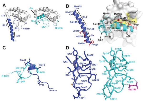
IFS Changes Conformation in Complex with SPN. A. The unbound IFS structure (left panel) shows an extended conformation of the C-terminal region (blue) whereas this region adopts a compact structure (cyan, right panel) in IFS bound to SPN (cf. Figure 1B). B. Hydrophobic residues (red) that are exposed in unbound IFS (left panel) become buried in the fold of bound IFS (right panel). Refolding of the C-terminus breaks helix α7 into two helical segments α7a and α7b. C. The N-terminal region of IFS is flexible and adopts different conformations in the free and bound structures. D. A network of hydrogen bonds stabilizes the structure of the SIL1 loop in free and bound structures of IFS (see text for details).

