

Abstract
Tn10 transposition, like all transposition reactions examined thus far, involves assembly of a stable protein–DNA transpososome, containing a pair of transposon ends, within which all chemical events occur. We report here that stable Tn10 pre-cleavage transpososomes occur in two conformations: a folded form which contains the DNA-bending factor IHF and an unfolded form which lacks IHF. Functional analysis shows that both forms undergo double strand cleavage at the transposon ends but that only the unfolded form is competent for target capture (and thus for strand transfer to target DNA). Additional studies reveal that formation of any type of stable transpososome, folded or unfolded, requires not only IHF but also non-specific transposase–DNA contacts immediately internal to the IHF-binding site, implying the occurrence of a topo– logically closed loop at the transposon end. Overall, transpososome assembly must proceed via a folded intermediate which, however, must be unfolded in order for intermolecular transposition to occur. These and other results support key features of a recently proposed model for transpososome assembly and morphogenesis.
Keywords: IHF/Tn10/transposition
Introduction
Tn10, a composite bacterial transposon, comprises two IS10 elements (R and L) plus internal sequences including a gene for tetracycline resistance. Tn10, or an individual IS10 element, can move into and out of chromosomes or plasmids in a non-replicative fashion (reviewed in Haniford and Chaconas, 1992; Mizuuchi, 1992; Kleckner et al., 1996; Yang and Mizuuchi, 1997; Mahillon and Chandler, 1998; Chalmers and Blot, 1999).
Tn10 transposition is accomplished via a series of four chemical steps which occur coordinately at the two ends of the element. The reaction initiates by hydrolytic nicking of the transferred strand adjacent to the terminal base pair of the transposon end. The resulting 3′ OH terminus then attacks the opposite, non-transferred strand in a transesterification reaction that yields a hairpin at the transposon terminus plus double strand cleaved flanking DNA. The hairpin is then nicked so as to regenerate the 3′ OH transferred strand terminus, which carries out a second transesterification reaction that covalently joins the transposon end to a target DNA strand (e.g. Kennedy et al., 1998; Figure 1A).

Fig. 1. (A) A diagram depicting the chemical steps of IS10/Tn10 transposition and associated protein–DNA complexes. (i) Stable transpososome or PEC formed without a divalent cation. (ii) Nicking of the transferred strand (TS) generating a 3′ OH. (iii) Hairpin formation and release of flanking DNA. (iv) Hydrolytic cleavage of the hairpin intermediate to regenerate 3′ OH and formation of DEB. (v) Target capture and strand transfer. (B) Organization of the outside end of IS10. The schematic diagram shows the terminal 70 bp of IS10 outside end. Transposase protection in PEC complexes is shown by a thin white box (present study). Major groove contacts between transposase and terminal DNA between bp 6 and 13 are indicated by a hatched box (H.Benjamin, J.Bender and N.Kleckner, unpublished). The IHF consensus sequence is located between bp 30 and 42. DNase I protection for IHF on the top and bottom strands of IS10 is indicated schematically by lines, with enhancements indicated by vertical slashes (Huisman et al., 1989). Additional protection observed in low salt PEC around bp 50–60 is indicated.
As in other transposition and site-specific recombination reactions (Mizuuchi, 1992; Wei et al., 1997; Segall, 1998), these chemical steps are carried out in the context of a stable protein–DNA transpososome that includes a pair of Tn10/IS10 ends plus transposase protein. Previous in vivo and in vitro studies of the Tn10 reaction have defined a pre-cleavage transpososome, also called a paired ends complex (PEC), as well as several complexes which correspond to the chemical intermediates that precede strand transfer and the final strand transfer complex (Haniford et al., 1991; Sakai et al., 1995). Target DNA enters the transposition reaction stably only at a late stage, after (and dependent upon) double strand cleavages at both transposon ends. A stable non-covalent co-complex between the corresponding transpososome complex and target DNA has been identified (Junop and Haniford, 1997; Sakai and Kleckner, 1997).
Earlier work has shown that a pre-cleavage transpososome can be assembled on short linear fragments encoding the outside end of IS10 plus some adjacent flanking DNA (e.g. Figure 1B). The IS10 portion of such a substrate generally contains the IS10 terminal inverted repeat sequence (bp 1–23), the immediately subterminal consensus sequence for binding of the accessory architectural factor IHF (bp 30–42) (Nash, 1996; Rice, 1997), plus additional internal DNA, typically ∼20 bp. PEC assembly in such a reaction requires only buffer components, monovalent cations, transposase and IHF (Sakai et al., 1995).
Intermediates in the assembly of stable Tn10 transpososomes have not been described. Analysis of in vitro reactions on circular plasmid substrates has shown, however, that supercoiling and IHF can substitute for one another in promoting transposon excision (Chalmers et al., 1998). Since such behavior is prototypical for formation of an IHF-mediated folded protein–DNA complex (e.g. Richet et al., 1986; Nash, 1990; Segall, 1998), such a complex was proposed as an obligatory step in transpososome assembly (Chalmers et al., 1998). In reactions on short fragment substrates, the absolute dependence of transpososome formation on IHF may be explained by the absence of supercoiling.
IHF and folded structures also play additional roles in Tn10 transposition. At sufficiently high IHF levels, and in the presence of DNA supercoiling, Tn10–target DNA interactions can be channeled entirely into a topologically and geometrically constrained intra-transposon mode which yields a single well-defined type of product (Chalmers et al., 1998).
These and other features of the Tn10 reaction as it occurs on covalently closed substrates have led to a speculative model for Tn10 transpososome assembly and morphogenesis (Chalmers et al., 1998). That model proposes that torsional tension is introduced into a topologically closed loop at one transposon end and that this tension is used to promote assembly of a stable transpososome in which the transposon domain is unfolded and from which IHF has been ejected. This unfolded form would then carry out normal (intermolecular) transposition. Under suitable conditions, however, refolding of the transpososome could occur, resulting in the channeled transposition pathway.
The current study further investigates the nature of, and requirements for, assembly of stable transpososomes using the short linear fragment substrate assay system for direct monitoring of protein–DNA complexes.
Results
Two forms of pre-cleavage transpososomes, t–PEC and b–PEC
We have found previously that incubation of transposase with a short IS10 outside end substrate DNA, along with IHF, yields a single pre-cleavage transpososome species (PEC), (Sakai et al., 1995). The current study began with an assessment of PEC formation as a function of IHF concentration (Figure 2A and B). In confirmation of previous results, no PEC is formed in the absence of IHF and, at higher IHF levels, the originally identified PEC is the only transpososome species. In addition, however, at lower and intermediate IHF concentrations, a second, slower migrating, complex is also observed (Figure 2A). This second complex also contains two transposon end fragments, i.e. is another form of PEC, by the same criterion used to define the original form (Sakai et al., 1995; data not shown). We refer to the two PEC species operationally as t–PEC (top PEC) and b–PEC (bottom PEC), respectively.

Fig. 2. Dependence of PEC formation on IHF concentration. (A) Paired ends complexes (PECs) were assembled under standard reaction conditions (without divalent cations). IHF was added, prior to transposase, at the indicated final concentration. Bands corresponding to the free fragment and the IHF–fragment complex are observed in addition to the two forms of the PEC (b–PEC and t–PEC). (B) A graph showing the relative levels of various complexes formed as a function of IHF concentration as shown in (A).
Reversible interconversion between b–PEC and t–PEC via addition and subtraction of IHF
At higher levels of IHF, the higher mobility form of PEC predominates. This is the opposite of the effect expected from a simple molecular difference due to the presence of IHF molecules, which should confer lower mobility. On the other hand, since IHF creates a sharp bend in DNA at its site of binding (Nash, 1996; Rice et al., 1996; Rice, 1997), the slower mobility t–PEC could represent an unfolded form, presumably lacking IHF, while the b–PEC could represent a more compact, folded form that contains IHF. To explore this possibility, we investigated whether the two forms could be interconverted by appropriate subtraction and addition of IHF.
We find that the b–PEC form can be converted to the t–PEC form by treatments expected to titrate IHF out of the complex. b–PECs were formed at 1 nM IHF, where no t–PECs are seen, and then exposed to a large excess of non-specific DNA (∼1 μg of supercoiled plasmid). This treatment converts all of the IHF-bound unreacted substrate present in the reaction mixture to the unbound (unshifted) form. Furthermore, all b–PECs disappear and nearly all complexes reappear at the t–PEC position; a small amount is seen near the well, perhaps bound to plasmid DNA (Figure 3A, compare lanes 1 and 2). b–PECs cannot have disassembled and reassembled into t–PECs under these conditions because addition of the same amount of non-specific DNA at the start of the PEC assembly reaction precludes formation of any visible complexes (data not shown). The same effect is achieved by addition of a double-stranded 33 bp oligonucleotide containing the high affinity H′ IHF-binding site from λ attP (Yang and Nash, 1995; Murtin et al., 1998) instead of the plasmid DNA. A very small amount of the IHF duplex (<2 pmol) suffices to shift essentially most b–PECs to the t–PEC position. In contrast, a control 33 bp duplex having the reverse complementary sequence has no effect on PEC mobility even at much higher concentration, though some loss of PEC was visible (∼40 pmol; Figure 3A, lanes 3–12).

Fig. 3. Reversibility of b–PEC and t–PEC by addition/subtraction of IHF. (A) PECs were formed under standard reaction conditions (4 nM input IHF) (lane 1). A 1 μg aliquot of non-specific DNA (pNK2704, also used as target DNA in Figures 6 and 7) was added after PEC formation (lane 2). A double-stranded IHF-binding site oligonucleotide or the reverse complement oligonucleotide was added after PEC formation as indicated (lanes 3–12). (B) Additional IHF was added to t–PEC formed as in (A), lane 2, as indicated. (C) A graph showing the IHF concentration-dependent transition from t–PEC to b–PEC and free substrate to IHF complex formation. The IHF concentration needed for 50% complex formation and t–PEC to b–PEC transition is indicated by vertical marks.
Conversely, t–PECs can be converted to b–PECs by addition of IHF. A reaction mixture containing only t–PECs was made by titration of IHF from a b–PEC-containing reaction, analogously to Figure 3A. Several identical aliquots of that reaction mixture were then incubated with increasing amount of IHF and examined for the array of complexes present. As the concentration of added IHF increases, t–PECs disappear and b–PECs (re)appear (Figure 3B and C). Additional findings suggest that IHF binding to/within an already formed transpososome is promoted and stabilized by surrounding features of the structure. (i) When IHF is added back to a t–PEC preparation, the IHF concentration at which b–PEC and t–PEC forms are equally abundant is lower than the level at which the unbound and IHF-bound forms of the substrate fragment are equally abundant, suggesting that the t–PEC transpososome has a higher affinity for IHF than does naked substrate fragment. (ii) Similarly, while HU cannot substitute for IHF in promoting transpososome formation (Sakai et al., 1995; data not shown), t–PECs formed by titration of IHF out of b–PECs can be fully refolded to complexes of b–PEC mobility by HU at concentrations of ∼130 nM or higher (data not shown), again implying that the transpososome is a more favorable substrate for binding of bend-promoting host factors than is naked DNA. (iii) The concentration of IHF-binding site oligonucleotide required to shift half of the b–PECs into t–PECs is higher than that required to shift half of the IHF-bound unreacted substrate fragment to the unbound form, suggesting that IHF may be more tightly bound within the transpososome than to the same sequence on simple duplex DNA.
DNase I footprinting of PECs
To investigate further the differences between b–PECs and t–PECs, the two forms of pre-cleavage transpososomes were subjected to footprinting analysis. Previous genetic and chemical interference studies have shown that transposon sequences throughout most of the terminal inverted repeat, bp 1–23, are relevant for successful transposition. Particularly strong interactions with transposase are inferred for bp 6–13, and the terminal base pairs 1–3 also appear to play special roles (Huisman et al., 1989; Haniford and Kleckner, 1994; Kleckner et al., 1996). For the current study, it was of interest to determine whether the DNase footprints for the two PEC forms cover the entire terminal repeat sequence and also, more specifically, to determine whether the b–PEC form, uniquely, exhibits evidence of protein binding at and/or beyond this sequence, as might be expected from a folded structure.
For this analysis, assembly reactions containing either b–PECs or t–PECs were prepared, treated very briefly with DNase I plus MgCl2 and, following quenching of the reaction with EDTA, loaded immediately onto a native acrylamide gel under tension. After electrophoresis, bands containing the appropriate complexes were excised and their DNA extracted and analyzed for cleavages on a denaturing polyacrylamide gel. Bands containing IHF-bound and protein-free substrate fragment were examined as controls. These experiments utilize the ‘standard substrate’ labeled only on the ‘top strand’ at the flanking donor DNA end (Figure 4; Materials and methods).
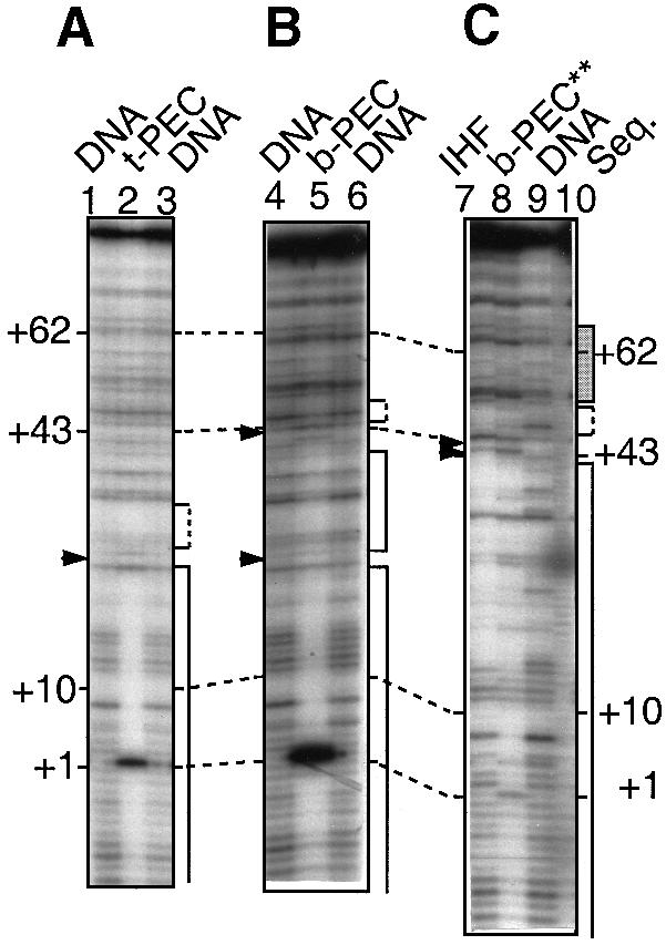
Fig. 4. DNase I footprinting of PEC complexes. t–PEC (lane 2), b–PEC (lane 5) and b–PEC** (lane 8) were formed under standard reaction conditions, except that 1 μg of non-specific plasmid DNA was added to form the t–PEC, and b–PEC** was formed under conditions which reduced the monovalent salt to 10 mM KCl and omitted the divalent salt. DNA was eluted from bands corresponding to the appropriate complex after treatment with DNase I and MgCl2, separated by electrophoresis through a native polyacrylamide gel and analyzed by denaturing polyacrylamide gel electrophoresis. Free DNA and IHF complexes treated similarly were also included as controls (lanes marked DNA and IHF, respectively). An enhancement of the band at +1 of the transposon end is due to the stimulation of cleavage by the presence of Mg2+. Regions of protection are indicated by solid line brackets; regions of uncertain protection by dashed line brackets; and regions of altered banding pattern by a gray box. Hypersensitive sites are indicated by filled triangles. Lane 10 is a ladder of bands generated by the mixture of the four dideoxy sequencing reactions.
The t–PEC footprint reveals a protected region that corresponds essentially to IS10's terminal inverted repeat sequence, with no evidence of any IHF footprint. Protection extends from second base pairs of transposon sequences, +2, to about +24 (a possible hypersensitive site occurs around +24); it is uncertain whether the region between +24 and +30 is protected (Figure 4A). At the terminal base pair, +1, an enhanced band is observed. This enhancement results from transposase-promoted cleavage at the end of the element, which occurs as a consequence of the brief exposure to Mg2+ required for DNase I digestion. No protection is observed in the consensus sequence core of the IHF-binding region, +30 to +42, nor is there any sign of the two diagnostic hypersensitive sites, at +43 and +45 (Yang and Nash, 1989; Kleckner et al., 1996)
The b–PEC footprint, in contrast, exhibits strong protection against DNase I cleavage from the terminus of the element, bp 2, through at least bp 45 and perhaps a few base pairs beyond, as expected from the combined footprints of transposase and IHF. Importantly, also, the hypersensitive sites (at +43 and +45) diagnostic of the IHF binding are now observed.
b–PECs were also analyzed under conditions of reduced salt concentration (10 mM KCl instead of the usual 100 mM, in addition to 25 mM NaCl from transposase dilution buffer). The footprint observed under these conditions closely resembled that for standard b–PECs in the region from bp 1 to 45, including the IHF-specific hypersensitive sites. In addition, however, in the region from ∼+45 to +70, the banding pattern was significantly different from that of b–PECs or t–PECs, suggesting protection from cleavage in this region. These findings pointed to the possibility of protein–DNA contacts in the folded structure which are too weak to be detected under standard conditions but stable enough to give a footprint under low salt conditions (also see below). Low salt b–PECs exhibited another, more subtle, unique feature: a decrease in protection between bp 1 and 5 as compared with standard b–PEC or t–PEC complexes.
b–PECs and t–PECs exhibit similar rates of flanking DNA release
The rates of transposon end cleavage by b–PEC and t–PEC complexes were examined in parallel. t–PECs were prepared by IHF titration of b–PECs and gel purified; half of the preparation was then converted back to b–PECs by addition of IHF. About 50% of complexes survive these procedures while the remainder dissociate, as seen by the presence of free substrate fragment (Figure 5A). Addition of Mg2+ in parallel to t–PEC and b–PEC samples resulted in release of flanking DNA from the transpososome as a result of processing to the hairpin stage or beyond (Figure 1A). Flanking DNA release occurs with very similar kinetics for both types of complexes (Figure 5B).

Fig. 5. Cleavage rates of b–PEC and t–PEC. (A) t–PEC complexes were purified by elution from a gel into standard reaction buffer. To half of the eluate, IHF was added to 4 nM. At t = 0, both reactions were adjusted to 4 mM MgCl2. Aliquots were withdrawn at the indicated time points and loaded directly onto a native polyacrylamide gel under tension. Curvature of the time course reflects the separation which occurs between loading at subsequent time points. (B) The flanking DNA band from (A) was quantitated by phosphoimager for the two reactions and plotted. Values were normalized to the amount of initial complexes. (C) IHF was either added or not added to a reaction such as the 20 min time point from the t–PEC reaction (A, right panel) and allowed to incubate for an additional 20 min before loading.
In the case of b–PECs, flanking DNA is first released at one end and then at the second end, with a corresponding discrete increase in the mobilities of the transpososome complexes (Sakai et al., 1995; Figure 5A, left panel). Most of the truncated transposon ends in the resulting complexes are fully cleaved (Sakai et al., 1995), though a low level of hairpin (Figure 1A) could be present. The two types of transpososomes are thus referred to as ‘single end break’ (SEB) and ‘double end break’ (DEB) complexes, respectively. Interestingly, cleaved complexes in the t–PEC reaction do not exhibit discrete mobilities but instead migrate as a more heterogeneous mixture. Nonetheless, these complexes represent the same two basic forms: if IHF is added to the t–PEC sample exposed to Mg2+ for 20 min, discrete bPEC, bSEB and bDEB complexes emerge (Figure 5C).
IHF releases post-cleavage transpososomes from non-covalent association with target DNA and (thereby) inhibits strand transfer
Tn10 ‘post-cleavage’ transpososome can associate stably and non-covalently with a target molecule, subsequent to, and dependent upon, release of flanking DNA at both transposon ends (Sakai and Kleckner, 1997). Such association requires divalent metal ion, but can be observed in the absence of strand transfer by substituting Ca2+ for Mg2+ or Mn2+. If Mg2+ is then added after target capture, strand transfer ensues. These events can be monitored using radiolabeled transpososomes and unlabeled supercoiled plasmid DNA. Target capture is assayed by electrophoresis through an appropriate two-phase gel, where the top half is composed of agarose and the bottom half of polyacrylamide. DEB–target DNA co-complexes migrate at the same position as free substrate DNA in the upper layer while free DEB complexes migrate as a distinct band within the lower layer. Strand transfer is also monitored in such gels, but separately: following removal of proteins from the DNA, transposon end substrate radiolabel in strand transfer products migrates at the position of linearized plasmid DNA.
In previous analyses of transpososome–target DNA interactions, only t–PEC transpososomes would have been examined, since addition of plasmid DNA as target would have titrated IHF out of the complexes. We therefore investigated whether b–PECs could carry out target capture and strand transfer. Post-cleavage (DEB) transpososomes were assembled in the presence of IHF on ‘pre-cleaved’ substrate fragments containing exposed transposon termini like those generated by transposase-promoted cleavage. Ca2+ was then added to the reaction mixture followed by target plasmid DNA. Then, after further incubation, the mixture was divided into a series of identical aliquots to which IHF was added at various levels. After further incubation, these mixtures were assayed for target capture and strand transfer. If no IHF is added, essentially all DEB complexes are associated with target DNA (Sakai and Kleckner, 1997; not shown). As the level of added IHF increases, a decreasing fraction of DEB transpososome label migrates with the target DNA and an increasing fraction migrates at the position of free DEB complexes (Figure 6A); at the highest IHF level examined, all DEB complexes are released from association with target DNA. Parallel analysis of these reaction mixtures in a standard polyacrylamide gel confirms that the recovered DEB complexes migrate at the same position as the original DEB complexes prior to addition of target DNA (Figure 6B).

Fig. 6. Effect of IHF on strand transfer and DEB–target co-complexes. (A) DEB–target co-complexes were assembled by incubating DEB made from pre-cleaved end fragments with 1 μg of target DNA (pNK2704). Additional IHF was added to the DEB–target co-complex reactions as indicated. Reactions were analyzed on split gels in which the top half was composed of 1% agarose to resolve co-complexes and the bottom half was composed of 5% polyacrylamide to resolve DEB complexes. *indicates the boundary between the two phases. (B) Reactions as in (A) were analyzed on polyacrylamide gels; DEB–target co-complexes migrate close to the wells of the gel. (C) Reactions were as in (A) except that MgCl2 was added to 4 mM 3 h after the addition of IHF. After overnight incubation, proteins were removed by phenol extraction and the strand transfer products analyzed on a polyacrylamide gel.
The effects of IHF on the level of DEB–target DNA association carry over to strand transfer. After withdrawal of aliquots for target interaction analysis, Mg2+ was added to each of the above reactions; after further incubations, strand transfer was assayed. If no additional IHF is added in the second phase of the transpososome preparation protocol, DEB DNA is converted quantitatively to a form in which it is covalently associated with nicked circular target DNA; then, as the level of added IHF increases, the level of strand transfer products decreases commensurately (Figure 6C).
Efficient assembly of PECs requires DNA, but not IS10-specific sequences, beyond the IHF-binding site
To investigate further the possibility that PEC formation involved protein–DNA contacts internal to the IHF-binding site, raised by DNase I protection studies above, we examined PEC formation with a set of substrate fragments isogenic to the standard substrate which retained 49 bp of flanking DNA plus bp 1–40 of the transposon end, but contained progressively less and less ‘internal’ transposon DNA beyond bp 40. Substrates carrying the terminal 65, 56, 50, 46 or 41 bp of transposon end sequences, plus 49 bp of adjacent flanking DNA, were examined in comparison with the standard substrate, which has 87 bp of transposon end DNA plus the 49 bp of flanking sequence. The deletion substrates exhibited progressively decreasing efficiencies of PEC formation under standard conditions: 51, 19, 6.4, 2.8 and ∼0.1% the level of the standard substrate, respectively (Figure 7A). The shortest substrate lacks contacts important for IHF binding (Rice et al., 1996), which probably explains its especially low activity. PECs formed on substrates having 46 bp or more of transposon end sequence still shift to a lower mobility upon addition of non-specific DNA, suggesting that they are all still capable of existing in both folded and unfolded forms. Furthermore, the progressively truncated substrates yield strand transfer products comparable with the relative levels of PEC formation (Figure 7A). There is a tendency for strand transfer levels to be somewhat higher than PEC levels; this might reflect the presence of strand transfer-proficient complexes at non-discrete positions in the gel. These results suggest that PEC assembly requires DNA to be present internal to the IHF-binding site.

Fig. 7. (A) Role of sequences beyond the IHF consensus sequence in the efficiency of PEC formation. Standard reactions were assembled on substrates with shortened transposon end DNA. The IHF consensus sequence is located from +30 to +42 of the Tn10 outside end (Huisman et al., 1989). Substrates with 41 (E41), 46 (E46), 50 (E5), 56 (E56) and 65 bp (E65) transposon end DNA were generated (Materials and methods). Reactions were assembled under standard conditions and 1 μg of plasmid DNA (pNK2704) was added as indicated. Strand transfer capacity was assayed by the addition of 1 μg of plasmid DNA and 4 mM MgCl2; proteins were removed prior to analysis of the products. The amount of radioactivity present in the PEC and strand transfer bands was quantitated, and the percentage of the input fragment which was present in PEC or strand transfer products was calculated and normalized to the values obtained for the standard substrate. Values shown are the average of two experiments. (B) Schematic diagram of two isogenic wild-type and scrambled substrates. (C) A graph showing the dependence of PEC formation on IHF concentration for the substrates in (B). Experimental conditions are as in Figure 2.
To determine whether the identity of the internal transposon DNA is important, i.e. whether IS10 sequence is required specifically or not, PEC formation was examined in parallel on a pair of isogenic substrate fragments differing in sequence in the critical region. Both substrates contained 5 bp of flanking DNA adjacent to 68 bp of transposon end DNA; of those 68 bp, the first 49 comprised wild-type IS10 outside end sequence in both cases, while the remaining segment, bp 50–68, comprised either the wild-type sequence or a random DNA sequence of similar base composition (Figure 7B; Materials and methods). These two substrates form PEC with equal efficiencies and with the mixture of t–PECs and b–PECs, implying that specific IS10 sequences in the subterminal region are not required for either transpososome assembly or for t–PEC–b–PEC differentiation (Figure 7C; compare with Figure 2B).
t–PECs arise by decay of b–PECs
Previous analyses of PEC formation and the results described above examined the array of products in end-point reactions, assayed after overnight incubation. We therefore also investigated the relative kinetic appearance of t–PECs and b–PECs. Transposase was added to reaction mixtures already containing substrate DNA, buffer components and IHF (which rapidly achieves equilibrium binding to substrate DNA, not shown) and PEC formation was then assayed as a function of time. At a relatively high IHF concentration (0.56 nM total), b–PECs are the only species formed and they appear rapidly, with about two-thirds of the final level appearing in <10 min and another one-third arising in what appears to be a second phase thereafter (Figure 8A). When such experiments are carried out at intermediate or low IHF concentrations (0.23 or 0.056 nM, respectively), the same kinetics are observed for b–PECs, with almost no t–PEC formation at early times. Instead, most t–PECs arise at late times, after nearly all b–PEC formation is completed (t ≥60 min; Figure 8B and C).

Fig. 8. Kinetics of PEC formation. (A–C) A detailed time course of PEC formation at three IHF concentrations: (A) 0.56 nM; (B) 0.23 nM; and (C) 0.056 nM. In each graph, the total amount of b–PEC, t–PEC and their sum at each time point from 0.5 min to 30 h were plotted. Some data points were omitted from the graphs to simplify the presentation. (D) A plot of the ratio of b–PEC/total PEC and t–PEC/total PEC computed from (A–C). An arrow at 60 min indicates a plateau of PEC formation, beyond which an increase of t–PEC corresponds with a decrease of b–PEC. Symbols: B = b–PEC, T = t–PEC, BT = b–PEC + t–PEC, L, M and H = low, medium or high IHF concentrations.
The late appearance of t–PECs could mean either (i) that t–PECs arise very slowly as a second species, or (ii) that t–PECs arise by unfolding of already assembled b–PECs. The latter interpretation is confirmed by the fact that, at both lower and medium IHF concentrations, among total PECs, the increase in the fraction of t–PECs is accompanied by a mirror symmetrical decrease in the fraction of b–PECs (Figure 8D). This relationship holds at both early times, when total PEC formation is increasing, and at later times, once PEC formation has ceased. In addition, the fact that the total PEC level remains constant at later time points further implies that the absolute number of t–PECs which appear is the same as the absolute number of b–PECs that disappear.
Additional experiments demonstrate that conversion of b–PECs to t–PECs fails to occur at lower salt concentrations (e.g. those used for b–PEC protection analysis described above). If PEC assembly is carried out at low or moderate IHF concentration but under low salt conditions, no t–PEC appears, even at late times. Furthermore, if non-specific DNA is added to b–PECs under low salt conditions, IHF is titrated off free DNA, but no shift to the t–PEC form occurs (data not shown). These findings suggest that non-specific protein–DNA contacts internal to the IHF-binding site stabilize b–PECs against unfolding.
Presumably the shift from b–PEC to t–PEC reflects the re-equilibration of transpososome-bound IHF amongst all of the DNA (and protein–DNA) species present in the reaction mixture according to their relative abundance, their IHF-binding affinities and the total IHF concentration. Higher IHF levels and lower salt concentrations favor the b–PEC form by, respectively, promoting bending and stabilizing non-specific DNA–protein contacts within the folded structure.
It is notable that the re-equilibration process is extremely slow, ∼50% complete after 240 min (Figure 8). This feature is not surprising and probably reflects primarily the very low concentration of DNA present in these reactions. For IHF's relative, HU protein, the rate of dissociation from DNA increases in proportion to total DNA concentration. This behavior is thought to reflect the fact that HU moves from one molecule to another via an intermediate in which the protein is bound to its starting position by only one of its two ‘arms’ (D.Pettijohn, personal communication). IHF probably exhibits the same behavior, as indicated not only by the strong structural and functional similarities to HU but also by documented behavioral asymmetry of the IHF heterodimer (Werner et al., 1994). The rate of IHF dissociation from transpososomes presumably is reduced even further by the fact that stable transpososomes have a higher affinity for IHF than does uncomplexed fragment DNA (above).
Discussion
Tn10 transpososome formation involves a folded intermediate
Transposon excision on covalently closed substrates requires either IHF or supercoiling. These two factors appear to act at the same step, inferred to be formation of a bend or node at the transposon end (Chalmers et al., 1998). Transpososome assembly on short linear fragment substrates is absolutely dependent upon IHF, implying that folding of the DNA is required (Sakai et al., 1995), presumably due to the absence of supercoiling in this system.
The current study reveals an additional requirement for transpososome assembly: the presence of non-specific DNA immediately beyond the IHF-binding site. This requirement presumably reflects a requirement for non-specific contacts with transposase protein in the relevant region as part of the IHF-mediated node. In fact, protein–DNA contacts are directly observable in this region by DNase I protection in the folded version of stable transpososomes (b–PECs). Thus these results provide additional evidence that a folded structure at the transposon end(s) is required for transpososome assembly.
Stable transpososomes occur in reversibly interconvertible folded and unfolded forms
Two forms of stable pre-cleavage transpososomes can be identified. The t–PEC form exhibits slower gel mobility, shows DNase I protection only within the terminal inverted repeat sequences of the transposon ends and can be generated from the b–PEC form by treatments which titrate IHF off its substrate fragment. The b–PEC form exhibits faster gel mobility, shows a DNase I protection pattern indicative of IHF binding plus transposase binding in the terminal inverted repeat and can be generated from the t–PEC form by addition of IHF. Taken together, these results strongly suggest that the b–PEC is an IHF-containing form in which the DNA components are bent, folded or wrapped, presumably in regions internal to the transposon end, while the t–PEC form lacks IHF in which the DNA components are not so constrained. Post-cleavage transpososomes that have undergone cleavage at one or both transposon ends also appear to exist in both folded and unfolded forms.
The b–PEC conformer appears to bind or cage IHF to some degree, as indicated by the fact that IHF bound within the complex is more resistant to titration by competitor sequences than is IHF bound on uncomplexed fragment. Similarly, the t–PEC form appears to be more disposed to interaction with host factors than is naked DNA, as indicated by the low concentration of IHF required and by the fact that HU will serve for t–PEC refolding but not for initial PEC formation. These effects are probably attributable in part to the availability of non-specific protein–DNA contacts internal to the IHF-binding site within the mature transpososome, indicated by the effects of lower salt concentrations on b–PEC DNase I protection patterns and t–PEC formation. It is not yet clear whether IHF is, or must be, bound to both transposon ends in the b–PEC form (or in any folded precursor form).
Only unfolded transpososomes are capable of non–covalent target capture (and strand transfer)
Non-covalent co-complexes between post-cleavage transpososomes and target DNA are dissociated by the presence of sufficient levels of IHF. Moreover, the released DEB transpososomes are in their folded conformation. We infer that the transpososome form bound to target DNA is unfolded and that refolding causes its release, i.e. the unfolded form of the transpososome is capable of stable co-complex formation with target DNA, while the folded form is not.
This conclusion is supported further by studies of Junop and Haniford (1997). Based on early results from the current study (Sakai, 1996), these workers went on to show that DEB transpososomes can be rendered competent for capture of a target DNA oligonucleotide by incubation with heparin. It was suggested that heparin acts by titrating IHF out of the transpososome. The findings above suggest that, alternatively, or in addition, heparin might act by competitively inhibiting non-specific DNA–transposase interactions in the region beyond the IHF site.
It remains to be determined whether the folded and unfolded transpososome conformers, and their attendant behaviors, differ only because of differences in the disposition of their DNA components (e.g. via steric hindrance effects) or whether there are also accompanying conformational changes within the transposase components of the transpososome.
Support for the molecular spring model of transpososome assembly and morphogenesis
Five features of the current data provide support for the previously proposed model of Chalmers et al. (1998).
(i) The proposed model requires the existence of a closed loop at the transposon terminus in order to permit the imposition of torsional tension. The presence of transposase–DNA contacts in the region just internal to the IHF-binding site implies the existence of simultaneous contacts at the terminal inverted repeat and the internal contact region (e.g. by analogy with a proposal made for λ Int protein; see Rice et al., 1997). This would in turn imply that a topologically closed terminal domain occurs, at least transiently, during transpososome assembly. In the model as originally proposed, the topologically closed domain was provided by interactions involving both ends plus a subterminal DNA region at a supercoiling-promoted plectosome branch point. This latter feature would have certain extra advantages that could act in combination with the local terminal loop identified here: interactions with the third DNA segment should provide extra resistance to the imposition of torsional tension, thus permitting imposition of a higher level of tension; interactions at the plectosome branch point also should serve to keep the two ends coordinated, precluding premature release of tension at either single end alone; finally, the presence of both the terminal loop and the cross-piece might provide for two-stage release of tension when the spring is unloaded.
(ii) The proposed model includes as a central feature the notion that intermolecular transposition is carried out by an unfolded form of the transpososome while constrained intra-transposon transposition would be carried out by a folded form. The differential behaviors of folded and unfolded transpososomes observed in the present study are in full accord with this notion. [In fact, an early form of the current results (Sakai, 1996) contributed to development of the spring model.] It is not known whether the folded transpososomes made on short fragments carry out channeled strand transfer or not. The channeled events observed on supercoiled substrates occur at target sites located ∼130 bp internal to the transposon end, which do not exist in the current fragment substrates.
(iii) Channeled transposition on plasmid substrates requires a higher concentration of IHF than transposon excision, from which it was inferred that refolding of the transpososome requires a higher IHF concentration than did its initial formation. The proposed model accounts for this finding because unloading of the spring introduces writhe of inhibitory handedness (i.e. of handedness opposite to that of negative supercoiling) into the transposon domain of the pre-DSB transpososome. Since such inhibition requires duplex DNA continuity between the two transposon ends, this feature should be absent during refolding of transpososomes formed on short fragment substrates. This in turn predicts that the concentration of IHF required for transpososome refolding in the current assay system would be the same as that required for assembly, or lower if the stable transpososome created the opportunity for additional stabilizing contacts, which is the result observed above.
(iv) The model proposed for plasmid substrates envisages that an unstable folded intermediate (Folded*) gives rise directly to a stable unfolded form (Unfolded-S), from which IHF has been ejected, but which can then be refolded (Refolded-S): Folded*→Unfolded-S→ Refolded–S. Ejection of IHF would be the result of (a) destabilization during imposition of tension into the closed terminal loop and (b) inhibition of rebinding/refolding for the reasons discussed above. In the current work, in contrast, a folded intermediate(s) gives rise to a stable folded transpososome that contains IHF; this folded form then unfolds to give a stable unfolded transpososome; and this unfolded form can then be refolded: Folded*→ Folded-S→Unfolded-S→Refolded-S.
This difference could be more apparent than real. For example, if the IHF ejected from the transpososome during loading of the spring actually remains bound by one arm (see discussion above), that IHF will rebind rapidly and efficiently within transpososomes formed on short fragment substrates but will be disfavored from rebinding within transpososomes formed on plasmid substrates, for reasons described in (iii) above. Also, if a higher level of torsional tension/stress is imposed in the presence of a plectosome branch point, as described in (i) above, the tendency for IHF eviction itself could be stronger on the plasmid substrates.
(v) Significant transposition occurs on plasmid substrates that appear to contain essentially no negative supercoiling even in the absence of IHF. On fragment substrates, in contrast, IHF seems to be absolutely required for formation of a stable transpososome. It is possible that a small fraction of the plasmid substrates retains one or several negative supercoils, thus eliminating this apparent contradiction. Alternatively, since IHF binding per se is not detectably different in the presence or absence of supercoiling, this difference might imply that covalent continuity between the transposon ends (in the absence of negative supercoiling) promotes stable transpososome formation and/or transpososon excision (the event assayed on plasmid substrates). In fact, the proposed model predicts that writhe of the same handedness as that provided by negative supercoiling will be introduced into the ‘flanking donor domain’ of the transpososome and that this effect feeds back into the transpososome assembly process and/or into the subsequent chemical steps.
Materials and methods
Transposition reaction components
DNA components. The standard substrate fragment contains 81 bp of DNA corresponding to the Tn10 outside end and is generated by a SalI–BglII digestion of pNK1935 (Huisman et al., 1989); six additional base pairs are provided by the polylinker sequence. Pre-cleaved end substrates possess 70 bp of the Tn10 outside end plus six additional bases from a BamHI linker. The shortened substrate fragments used in Figure 7 were constructed by site-directed mutagenesis (Kunkel et al., 1987) of pNK1935 to engineer restriction enzyme sites at the desired locations. pJS300 = a BglII site at bp +41, pJS301 = a BglII site at bp +46, pJS302 = a BamHI site at bp +50, pJS303 = an XbaI site at bp +55; a naturally occurring NdeI site at bp 65 was also used. Substrates were generated by digestion with BglII (pJS300 and pJS301), with BamHI (pJS302) and with XbaI + BglII (pJS303). Digestion of pNK1935 with BglII and NdeI was used to produce a substrate with 65 bp transposon end DNA via a naturally occurring NdeI site. The substrate generated by BamHI digestion possesses slightly shorter flanking DNA because there is a BamHI site upstream of the BglII site normally used to generate the standard fragment. Substrates were labeled by filling in with [α–32P]dATP (NEN, 6000 Ci/mmol) and avian myeloblastosis virus reverse transcriptase (Promega). For the DNase I footprinting experiments, the standard substrate was labeled only at the BglII end of the fragment. Wild-type and mutant substrates shown in Figure 7B were constructed from 73 bp oligonucleotides comprising 5 bp of the flanking DNA (5′-GGGCC-3′ on the non-transferred strand) and 68 bp of IS10 end sequence; the mutant substrate is identical to wild-type except that the sequence between bp 50 and 68 has been replaced by a random sequence (5′-TATCCATCTTCGAATATGA-3′). These substrates were labeled by γ-ATP (6000 Ci/mmol; NEN) and T4 polynucleotide kinase (NEB), phenol:chloroform extracted, passed twice through G-25 spin columns (Pharmacia) and resuspended at 100 000 c.p.m./μl.
IHF was titrated in the reactions by plasmid DNA (pNK2704, which was also used when a target DNA was necessary), or by an IHF-binding site oligonucleotide, a double-stranded 33mer corresponding to the H′ site of attP in bacteriophage λ (Yang and Nash, 1989) which was synthesized. The reverse complement site which has a reduced affinity for IHF was also synthesized as a control.
Transposition reaction. Standard reaction conditions are essentially as described in Sakai et al. (1995), except that reactions contained 4 mM CaCl2 (unless otherwise indicated). IHF was kindly provided by P.Errada. In experiments assaying the formation of the PEC, DNA and buffer were added to the reaction tube first; IHF was added next and transposase was added last. Standard reactions contained 4 nM input IHF. To analyze other aspects of the reaction, IHF, HU, IHF-binding site oligonucleotide or plasmid DNA was added at the indicated levels subsequent to formation of complexes. For analysis of cleavage or strand transfer, the reactions were supplemented to 4 mM MgCl2 as indicated. Reactions used to analyze synaptic complex–target DNA co-complexes or strand transfer contained 1 μg of pNK2704 as the target DNA. To analyze strand transfer products, proteins were removed by phenol:chloroform extraction.
Reactions were analyzed by separation through a 5% (29:1) polyacrylamide gel or a vertical split gel (Figure 6A) in which the top half consisted of 1% agarose and the bottom half of polyacrylamide. Complexes of interest were purified away from other reaction components by elution of the specific complex from a gel slice into standard reaction buffer by diffusion at room temperature for at least 24 h. Cleavage and strand transfer reactions were carried out with such complexes as usual except that the final concentration of intact complexes in the eluates was usually about one-fifth the concentration of complexes in the standard complete reaction. Quantification of the relative level of products was by phosphoimager.
DNase I footprinting
DNase I footprinting was carried out on PEC complexes formed under three different conditions. Standard 136 bp BglII–SalI fragments were radiolabeled only at the BglII end, then purified as usual. Complexes were formed under normal salt conditions including 4 mM CaCl2, in both the presence and absence of 1 μg of target DNA, as well as low salt conditions (10 mM KCl). DNase I (BRL) and MgCl2 were added at several concentrations, and allowed to incubate for several different time periods. At these times, EDTA was added to 25 mM to stop the digestion, and the whole reaction was loaded immediately onto a native polyacrylamide gel under tension. Gel slices corresponding to PEC, IHF–fragment complexes and DNA alone were excised and the DNA eluted by diffusion. DNA was concentrated by ethanol precipitation and analyzed on a denaturing polyacrylamide gel (8 or 10%, 19:1).
Kinetic analysis
Cleavage analysis was carried out as described previously (Sakai et al., 1995). For the kinetic analysis of PEC formation, 20× reactions were set up at the indicated IHF concentrations (low = 0.056 nM; medium = 0.23 nM and high = 0.56 nM) and samples were drawn. The earliest sample was taken at 0.5 min and then at 5, 10, 20, 30 and 45 min, 1 h, 1.5 h, and between 2 and 10 and 24 and 30 h at 2 h intervals. The samples up to 2 h were loaded in one 5% native polyacrylamide gel under tension. Samples from 4 to 10 h were loaded in a second gel and the overnight samples were analyzed on a separate gel. For the graphs in Figure 8, some intermediate data points were omitted to simplify the presentation.
Acknowledgments
Acknowledgements
This research was supported by a grant to N.K. from the National Institutes of Health (GM 25326) and to X.Y. from NIH/NIGMH (fellowship 1 F32 GM20119).
References
- Chalmers R. and Blot,M. (1999) Insertion sequences and transposons. In Charlebois,R.L. (ed.), Organization of the Prokaryotic Genome. American Society for Microbiology, Washington, DC, pp. 151–169. [Google Scholar]
- Chalmers R., Guhathakurta, A., Benjamin, H. and Kleckner, N. (1998) IHF modulation of Tn10 transposition: sensory transduction of supercoiling status via a proposed protein–DNA molecular spring. Cell, 93, 897–908. [DOI] [PubMed] [Google Scholar]
- Haniford D.B. and Chaconas, G. (1992) Mechanistic aspects of DNA transposition. Curr. Opin. Genet. Dev., 2, 698–704. [DOI] [PubMed] [Google Scholar]
- Haniford D. and Kleckner, N. (1994) Tn10 transposition in vivo: temporal separation of cleavages at the two transposon ends and roles of terminal base pairs subsequent to interaction of ends. EMBO J., 13, 3401–3411. [DOI] [PMC free article] [PubMed] [Google Scholar]
- Haniford D.B., Benjamin, H.W. and Kleckner, N. (1991) Kinetic and structural analysis of a cleaved donor intermediate and a strand transfer intermediate in Tn10 transposition. Cell, 64, 171–179. [DOI] [PubMed] [Google Scholar]
- Huisman O., Errada, P.R., Signon, L. and Kleckner, N. (1989) Mutational analysis of IS10's outside end. EMBO J., 8, 2101–2109. [DOI] [PMC free article] [PubMed] [Google Scholar]
- Junop M.S. and Haniford, D.B. (1997) Factors responsible for target site selection in Tn10 transposition: a role for the DDE motif in target DNA capture. EMBO J., 16, 2646–2655. [DOI] [PMC free article] [PubMed] [Google Scholar]
- Kennedy A.K., Guhathakurta, A., Kleckner, N. and Haniford, D.B. (1998) Tn10 transposition via a DNA hairpin intermediate. Cell, 95, 125–134. [DOI] [PubMed] [Google Scholar]
- Kleckner N., Chalmers,R.M., Kwon,D., Sakai,J. and Bolland,S. (1996) Tn10 and IS10 transposition and chromosome rearrangements: mechanism and regulation in vivo and in vitro. In Saedler,H. and Gierl,A. (eds), Current Topics in Microbiology and Immunology. Springer-Verlag, Berlin, pp. 49–82. [DOI] [PubMed] [Google Scholar]
- Kunkel T.A., Roberts, J.D. and Zakour, R.A. (1987) Rapid and efficient site-specific mutagenesis without phenotypic selection. Methods Enzymol., 154, 367–382. [DOI] [PubMed] [Google Scholar]
- Mahillon J. and Chandler, M. (1998) Insertion sequences. Microbiol. Mol. Biol. Rev., 62, 725–774. [DOI] [PMC free article] [PubMed] [Google Scholar]
- Mizuuchi K. (1992) Transpositional recombination: mechanistic insights from studies of Mu and other elements. Annu. Rev. Biochem., 61, 1011–1051. [DOI] [PubMed] [Google Scholar]
- Murtin C., Engelhorn, M., Geiselmann, J. and Boccard, F. (1998) A quantitative UV laser footprinting analysis of the interaction of IHF with specific binding sites: re-evaluation of the effective concentration of IHF in the cell. J. Mol. Biol., 284, 949–961. [DOI] [PubMed] [Google Scholar]
- Nash H.A. (1990) Bending and supercoiling of DNA at the attachment site of bacteriophage λ. Trends Biochem. Sci., 15, 222–227. [DOI] [PubMed] [Google Scholar]
- Nash H.A. (1996) The HU and IHF proteins: accessory factors for complex protein–DNA assemblies. In Lin,E.E.C. and Lynch,A.C. (eds), Regulation of Gene Expression in Escherichia coli, R.G.Landes Co., Austin, TX, pp. 149–179. [Google Scholar]
- Rice P.A. (1997) Making DNA do a U-turn: IHF and related proteins. Curr. Opin. Struct. Biol., 7, 86–93. [DOI] [PubMed] [Google Scholar]
- Rice P.A., Yang, S., Mizuuchi, K. and Nash, H.A. (1996) Crystal structure of an IHF–DNA complex: a protein-induced DNA U-turn. Cell, 87, 1295–1306. [DOI] [PubMed] [Google Scholar]
- Richet E., Abcarian, P. and Nash, H.A. (1986) The interaction of recombination proteins with supercoiled DNA: defining the role of supercoiling in λ integrative recombination. Cell, 46, 1011–1021. [DOI] [PubMed] [Google Scholar]
- Sakai J. (1996) Characterization of protein:DNA complexes in Tn10 transposition. PhD thesis, Harvard University, Cambridge, MA.
- Sakai J. and Kleckner, N. (1997) The Tn10 synaptic complex can capture a target DNA only after transposon excision. Cell, 89, 205–214. [DOI] [PubMed] [Google Scholar]
- Sakai J., Chalmers, R.M. and Kleckner, N. (1995) Identification and characterization of a pre-cleavage synaptic complex that is an early intermediate in Tn10 transposition. EMBO J., 14, 4374–4383. [DOI] [PMC free article] [PubMed] [Google Scholar]
- Segall A.M. (1998) Analysis of higher order intermediates and synapsis in the bent-L pathway of bacteriophage λ site-specific recombination. J. Biol. Chem., 273, 24258–24265. [DOI] [PubMed] [Google Scholar]
- Wei S.Q., Mizuuchi, K. and Craigie, R. (1997) A large nucleoprotein assembly at the ends of the viral DNA mediates retroviral DNA integration. EMBO J., 16, 7511–7520. [DOI] [PMC free article] [PubMed] [Google Scholar]
- Werner M.H., Clore, G.M., Gronenborn, A.M. and Nash, H.A. (1994) Symmetry and asymmetry in the function of E.coli integration host factor: implication for target identification by a DNA-binding protein. Curr. Biol., 4, 477–487. [DOI] [PubMed] [Google Scholar]
- Yang W. and Mizuuchi, K. (1997) Site-specific recombination in plane view. Structure, 5, 1401–1406. [DOI] [PubMed] [Google Scholar]
- Yang C.C. and Nash, H.A. (1989) The interaction of E.coli IHF protein with its specific binding sites. Cell, 57, 869–880. [DOI] [PubMed] [Google Scholar]
- Yang S.W. and Nash, H.A. (1995) Comparison of protein binding to DNA in vivo and in vitro: defining an effective intracellular target. EMBO J., 14, 6292–6300. [DOI] [PMC free article] [PubMed] [Google Scholar]