

Abstract
In noninvasive high-intensity focused ultrasound (HIFU) treatment, formation of a large tissue lesion per sonication is desirable for reducing the overall treatment time. The goal of this study is to show the feasibility of enlarging tissue lesion size with a dual-focus therapeutic ultrasound transducer (DFTUT) by increasing the depth-of-focus (DOF). The proposed transducer consists of a disc- and an annular-type element of different radii of curvatures to produce two focal zones. To increase focal depth and to maintain uniform beamwidth of the elongated DOF, each element transmits ultrasound of a different center frequency: the inner element at a higher frequency for near field focusing and the outer element at a lower frequency for far field focusing. By activating two elements at the same time with a single transmitter capable of generating a dual-frequency mixed signal, the overall DOF of the proposed transducer may be extended considerably. A prototype transducer composed of a 4.1 MHz inner element and a 2.7 MHz outer element was fabricated to obtain preliminary experimental results. The feasibility the proposed technique was demonstrated through sound field, temperature and thermal dose simulations. The performance of the prototype transducer was verified by hydrophone measurements and tissue ablation experiments on a beef liver specimen. When several factors affecting the length and the uniformity of elongated DOF of the DFTUT are optimized, the proposed therapeutic ultrasound transducer design may increase the size of ablated tissues in the axial direction and, thus, decreasing the treatment time for a large volume of malignant tissues especially deep-seated targets.
Keywords: Ultrasound, Therapy, Transducer, Depth-of-focus, Dual-curved aperture, Dual-focus, Dual-frequency, DFTUT, Bioheat transfer equation, Thermal dose
INTRODUCTION
In recent years, a number of clinical studies aimed at examining the efficacy of noninvasive ultrasound therapy have shown that this technique is feasible for treatment of malignant tissues in organs such as the prostate, liver, kidney and breast (Daum et al. 1999; Furusawa et al. 2007; Murat et al. 2009). Although high-intensity focused ultrasound (HIFU) therapy is effective in destroying tissues noninvasively with shorter recovery times and lower side-effects than invasive surgical techniques (Vaezy et al. 2001), it still suffers from a relatively long treatment time for ablation of large tissue volumes due to a small focal zone per each ultrasound emission (ter Haar 2000).
Several techniques have been developed to decrease the treatment time of noninvasive ultrasound therapy. One of them is the generation of multi-foci with a phased array transducer capable of electronic focusing and steering (Daum et al. 1999; Ebbini et al. 1989; Wan et al. 1996). In addition, multi-zone transmit focusing, which is usually used for imaging, can increase ablated tissue lesions in the axial direction (Do-Huu and Hartemann 1982). However, the conventional multi-foci technique and multi-zone transmit focusing scheme requires a complex array architecture. In addition, numerous electronic components including high-power amplifiers and time delay components are required to activate and control each element independently. Although several investigators have used specially designed lenses and conical shape transducers to increase depth-of-focus (DOF), most studies were focused on enhancing imaging performance (Burckhardt et al. 1973; Patterson and Foster 1982; Trzaskos and Young 1987). A few researchers have proposed a split-focusing technique to generate multi-foci simultaneously with a geometrically divided transducer, or a transducer with sectional electrode (Patel et al. 2008; Sasaki et al. 2003; Seip et al. 2001) driven by voltages of different phases. Recently, the toric transducer was developed to generate large ablated lesions (Melodelima et al. 2009). The aforementioned studies have focused on producing broad tissue lesions in the lateral and elevational directions.
In this article, we focus on the development of a specially designed therapeutic ultrasound transducer for reducing the treatment time of large tumors in high-intensity ultrasound therapy by increasing DOF in the axial direction. The proposed transducer is composed of a concentric disc- and an annular-type element and each-element has a different radius of curvature to produce two focal zones upon one excitation called dual-focus therapeutic ultrasound transducer (DFTUT). Two different center frequencies are used for simultaneous dual-zone transmit focusing and thus result in an enhanced focal depth. Each element is made of a piezoelectric composite material of a different thickness and subsequently optimized for transmitting ultrasound corresponding to its own resonant frequency. Thus, both elements work like band-pass filters of the excitation signal. These properties enable the proposed transducer to be activated by a single transmitter capable of generating a dual-frequency mixed signal. The center frequency and the dimension of each element can be optimized based on the application considering a target size and distance. In addition, the relative geometric focus offset between two different focal points and the output power of each element may affect the uniformity of the extended DOF and the lateral beam-width. A good alignment between these two elements in the fabrication process is a critical step to achieve a uniform compound beam profile in the axial and lateral direction.
As a preliminary experiment for feasibility of the proposed method, we fabricated a prototype DFTUT and its performance was demonstrated by hydrophone measurements and lesion formation tested on a piece of beef liver. Sound field simulations were conducted to obtain proper design specifications for the DFTUT and predict its performance. In addition, numerical simulations for the thermal effect on a tissue with bioheat transfer/thermal dose equations (Pennes 1948; Saporeto and Dewey 1984) yielded results on the estimated temperature/thermal dose distribution in the extended DOF for the DFTUT.
METHODS
Transducer design
Clinically the efficacy of a focused therapeutic transducer may be estimated from its −6 dB intensity contour of the focal zone (ter Haar 2000). Along the axis of propagation, the effective focal zone is defined by the DOF, which is related to the square of the f-number (focal depth/aperture size) and the wavelength (Shung 2006). Unfortunately, the DOF is sometimes sacrificed for the sake of generating sufficiently high intensity for tissue treatment. Thus, a specially designed DFTUT is proposed as shown in Figure 1 to increase the DOF while maintaining the necessary ultrasound intensity level for therapy. The DFTUT is composed of a disc-type-inner element and an annular-type-outer element with different radii of curvatures. The number of annular elements can be increased depending on the desired DOF. In this article, a single annular element was used for simulation and the preliminary experiment. The inner and outer elements of the DFTUT have 4.1 MHz and 2.7 MHz center frequencies with 19 mm and 24 mm radii of curvatures, respectively. In this case, the relative geometric focus offset between two focal depths was 5.24 mm as shown in Figure 1a. Note that the center frequencies, dimension and radii of curvatures can be chosen based on applications. The relative geometric focus offset was determined considering the overlapped zone of two elements at higher than −6 dB. The electrodes of the elements were connected together allowing ultrasound at two different frequencies to be simultaneously emitted to the two focal zones with a single transmitter that generates a continuous wave (CW) signal at two frequencies. The relative intensity for each element can be controlled by changing the amplitude of the two-frequency components in the input signal. The electrical impedance for inner and outer elements should be matched to that of the system mainly with a power amplifier for balanced output power.
Fig. 1.

Schematic diagram of the dual-focus therapeutic ultrasound transducer (DFTUT) with specification: (a) side view and (b) front view. Note that the relative geometric focus offset between two focal points is 5.24 mm.
The diameters of the inner and outer elements were 12 mm and 21 mm, respectively. Under these conditions, the −6 dB lateral beamwidth of the DFTUTwas similar to those obtained by inner and outer elements excited independently. The overall DOF for the DFTUT can be increased by minimizing the overlapping DOF regions generated by these two elements.
Sound-field simulation
To evaluate the performance and to obtain design specification of the DFTUT, the on-axis transmit beam profile was computed with the Field-II (Jensen and Svendsen 1992) simulation program derived from the Tupholme-Stepanishen method (Stepanishen 1971; Tupholme 1969). The two signals were simultaneously emitted to the target via the inner and outer elements of the dual-curved aperture to model the amplitude and phase interaction between two waves of different frequencies in the transmit-field. The dual-curved aperture was created with Field-II’s automatic meshing aperture generation as shown in Figure 2 and two waveforms of different frequencies were assigned to each element. This method was compared with a post-sum approach, i.e., sum of two transmit-field profiles for each aperture. There are low-level discrepancies in the time and frequency responses of scanlines and final beam profiles implemented by these two schemes given that the simulation is an approximation. In the final beam profiles, the difference between two schemes in −6 dB and −20 dB axial beamwidths were approximately 1 mm and 2 mm, respectively.
Fig. 2.

Schematic diagram of the dual-focus therapeutic ultrasound transducer (DFTUT) aperture used in the Field-II simulation. The radii of curvatures for inner and outer elements are 19 mm and 24 mm, respectively. The diameters of inner and outer elements are 12 mm and 21 mm, respectively.
The transducer aperture was apodized using the Hanning window and segmented by 300 μm rectangular elements. The radii of curvatures for inner and outer elements are 19 mm and 24 mm, respectively. The 4.1 MHz and 2.7 MHz input signals of 30% −6 dB bandwidth were assigned to each aperture based on the expected output from the prototype transducer without a backing layer. The sampling frequency was 40 times of the 4.1 MHz frequency and the amplitude of each frequency component was the same. The lateral and axial grid sizes were 20 μm and 100 μm, respectively. The relative geometric focus offset between two focal points was 5.24 mm. In this distance, the −2 dB contours off the maximal peaks for the two signals in Figure 3 and Figure 4 cross each other. Table 1 shows the specification of the DFTUT. Two kinds of simulations were conducted using the properties of the two different media such as water and liver. The results of these simulations are summarized in Table 2 and are displayed for water only in Figure 3 through Figure 5.
Fig. 3.
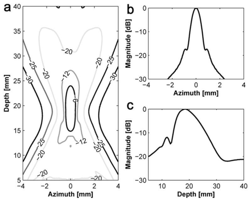
Transmit beam profile of the inner element with 19 mm focal depth: (a) a contour plot in the decibel scale, (b) lateral beam profile and (c) axial beam profile.
Fig. 4.
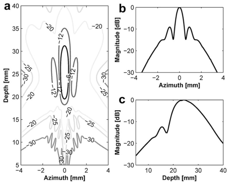
Transmit beam profile of the outer element with 24 mm focal depth: (a) a contour plot in the decibel scale, (b) lateral beam profile and (c) axial beam profile.
Table 1.
Specifications of the dual-focus therapeutic ultrasound transducer (DFTUT) for the sound field simulation
| Inner element | Outer element | |
|---|---|---|
| Center frequency | 4.1 MHz | 2.7 MHz |
| Diameter | 12 mm | 21 mm |
| Geometric focus | 19 mm | 24 mm |
| F-number | 1.6 | 1.1 |
| Relative geometric focus offset | 0 mm | 5.64 mm |
| Water attenuation coefficient† | 0.002 dB/cm MHz2 | |
| Liver attenuation coefficient‡ | 0.43 dB/cm MHz | |
(Shung 2006);
(Parker 1983).
Table 2.
Simulated −6 dB DOF, −6 dB lateral beamwidth and sidelobe for several transducers
| Medium |
|||
|---|---|---|---|
| Water | Liver | ||
| 4.1 MHz inner element | −6 dB DOF [mm] | 9.1 | 9.2 |
| −6 dB lateral beamwidth [mm] | 0.81 | 0.85 | |
| Sidelobe [dB] | −17 | −17.55 | |
| 2.7 MHz outer element | −6 dB DOF [mm] | 11.7 | 11.9 |
| −6 dB lateral beamwidth [mm] | 0.72 | 0.76 | |
| Sidelobe [dB] | −9 | −9.2 | |
| 3.4 MHz single element | −6 dB DOF [mm] | 4.4 | 4.7 |
| −6 dB lateral beamwidth [mm] | 0.64 | 0.68 | |
| Sidelobe [dB] | −18 | −17.3 | |
| DFTUT | −6 dB DOF [mm] | 15.4 | 14.7 |
| −6 dB lateral beamwidth [mm] | 0.75 | 0.73 | |
| Sidelobe [dB] | −9 | −9.4 | |
DFTUT = dual-focus therapeutic ultrasound transducer; DOF = depth-of-focus.
Fig. 5.
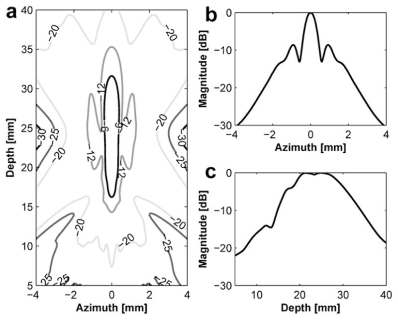
Transmit beam profile of the dual-focus therapeutic ultrasound transducer (DFTUT): (a) a contour plot in the decibel, (b) lateral beam profile and (c) axial beam profile.
Figure 3 and Figure 4 show the transmit beam profiles of the DFTUT’s inner and outer elements excited independently. The contour plots in Figure 3a and Figure 4a display the relative intensity in the decibel scale. Figure 3b and Figure 4b show the lateral beam profile of each element at maximal peak. The −6 dB lateral beamwidths of inner and outer elements were 0.81 mm and 0.72 mm, but the sidelobes were −17 dB and −9 dB. Because outer element has a ring type aperture, the sidelobe is higher and the lateral beamwidth is narrower than a disk type aperture. Figure 3c and Figure 4c show the axial beam profile of each element and −6 dB DOF were 9.1 mm and 11.7 mm, respectively. Figure 5 shows transmit beam profile of the DFTUT at water medium. Its −6 dB DOF was 1.7 and 1.3 times larger than those obtained with inner and outer elements, respectively. The −6 dB lateral beamwidth of the proposed transducer was 0.75 mm, which was close to those of inner and outer elements excited independently. The −9 dB sidelobe level was close to outer element. As a comparison, a single focused transducer with design parameters equal to the mean of the design parameters for the DFTUT (center frequency 3.4 MHz, focal depth = 21.5 mm and diameter = 21 mm) was also simulated (Fig. 6). The DFTUT’s −6 dB DOF was 3.5 times larger, its −6 dB lateral beamwidth was 0.11 mm broader and the sidelobe was 9 dB higher than those obtained with the single focused transducer. In the case of liver, the extended −6 dB DOF for the DFTUT was 3.1 times larger than 3.4 MHz single element transducer. The sidelobe of the DFTUT can be changed by controlling the dimension of outer element. Note that the medium for this simulation was single layer, which was homogeneous with a single value for the attenuation coefficient.
Fig. 6.
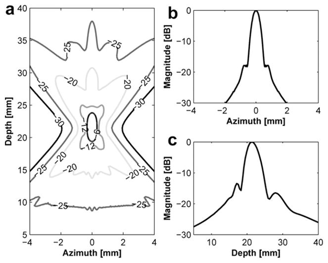
Transmit beam profile of the single focused transducer with 21.5 mm focal depth: (a) a contour plot in the decibel, (b) lateral beam profile and (c) axial beam profile.
Typically, the high sidelobe level may cause undesired tissue damage in adjacent normal tissues. However, sometimes it was used for the broader lesion formation to decrease treatment time of a large tumor (Wu et al. 1999).
Bioheat/thermal dose simulation
A bioheat transfer simulation was performed with the simulated acoustic pressure field. The Pennes bioheat transfer equation (Pennes 1948) was approximated by the equation below and numerically solved with Matlab (The MathWorks Inc., Natick, MA. USA).
| (1) |
Where ρt is the tissue density, ct is the specific heat of tissue, kt is the tissue thermal conductivity, Wb is the blood perfusion rate, cb is the specific heat of blood, Ta is the arterial temperature, T is the tissue temperature and q is the absorbed ultrasound power density defined below (Nyborg 1981). Table 3 shows the parameters used for this simulation (Damianou et al. 1994, 1997; Fjield et al. 1996; Lin et al. 2001) targeting a soft tissue.
Table 3.
Parameters for bioheat transfer simulation
| Density ρt (kg/m3) | 1070 |
| Specific heat of tissue ct (J/kg/°C) | 3770 |
| Specific heat of blood cb (J/kg/°C) | 3770 |
| Blood perfusion Wb (kg/m3/s) | 5 |
| Thermal conductivity kt (W/m/°C) | 0.5 |
| Ultrasound absorption coefficient α (Np/m/MHZ) | 5 |
| (2) |
Where α is the acoustic absorption coefficient and P is the measured pressure at focal point and ρ is the density and c is the velocity. In this work, the acoustic intensity profile for the input for eqn (1) was calculated from the Field-II program using the measured acoustic pressure of 6.1 MPa. A numerical finite-difference method was used for solving the bioheat transfer equation by replacing the derivative equation with difference quotients. The X-axis range was from −6 mm to 6 mm and the Z-axis range was from 1.5 mm to 46.5 mm. The X- and Z- step sizes were 0.02 mm and 0.4 mm, respectively. The time step was 0.05 s and simulation time was 30 s. Figure 7a shows the estimated temperature distribution for DFTUT in two-dimensional (2-D) modeling. The maximum temperature recorded was 83°C at 20 mm, which is near the geometrical focus of the inner element, and the second peak has 60°C at 26 mm, which is near the geometrical focus of the outer element. The temperature profile covers approximately 5 mm × 28 mm with different temperature ranges.
Fig. 7.

(a) Simulated temperature distribution and (b) thermal dose for dual-focus therapeutic ultrasound transducer (DFTUT) by targeting a liver layer. The position of the transducer was on the bottom side. Note that the lateral axis scale of (b) is different from the (a).
It was previously demonstrated that the thermal dose eqn (3) could predict the coagulation necrosis of the tissue based on temperature and duration of heating (Sapareto and Dewey 1984). In this simulation, the time calculated by numerical integration at some reference temperature was equivalent to the thermal dose. Note that the temperature distribution of the bioheat transfer equation was used for the input of the thermal dose eqn (3) (Damianou et al. 1994; Owen et al. 2010).
| (3) |
where t43 is the equivalent time at 43°C and Tt is the average temperature during Δt. The value of R was 0.25 for temperatures lower than 43°C and 0.5 for higher than 43°C. The lesion size was predicted with the threshold thermal dose for necrosis equivalent exposure of 43°C for 240 min (Damianou et al. 1994, 1995). Figure 7b shows the contour plot of the equivalent thermal dose distribution for 60 min and 240 min at reference 43°C. The size difference between 60 min and 240 min was lower than 0.6 mm in the axial direction. In the 240 min contour plot, the maximal lateral width and axial length were approximately 1 mm and 12 mm, respectively.
Transducer fabrication
A prototype DFTUT was built following the specifications summarized in Table 4. This transducer has 1–3 piezoelectric composite elements using PZT4 (840; APC Company, Mackeyville, PA, USA) and epoxy (EPO-TEK 314; Epoxy Technology, Billerica, MA, USA) so that they can be spherically shaped, and to reduce acoustic impedance mismatch between a transducer and a medium. PZT4 has high Curie temperature and high mechanical Q and, thus, is an excellent material for therapeutic transducer designs. In addition, the epoxy used has a high glass transition temperature (100°C), which makes it less susceptible to failure during operation. For the 4.1 MHz inner element, a pre-poled PZT4 plate was diced with a 35 μm wide blade to make the 1–3 composite. The composite pitch was 250 μm and the post-widths were 215 μm. After a cleaning and drying procedure, the kerfs were filled with unloaded EPO-TEK 314. After the composite was cured at 120°C for 3 h, the composite was then lapped to a final thickness of 450 μm and heat pressed to a spherically curved shape at 130°C using a rubber mold and a chrome/steel ball. The same process was used to fabricate the outer ring element. After heat pressing, the two elements were carefully bonded together and a 0.5 μm thick gold/chrome-sputtered layer was used as the electrode for both the signal and ground electrodes. No matching and backing layers were used in the prototype transducer to minimize heat absorption and to maximize transmit intensity. Figure 8 shows a photograph of the finished prototype DFTUT. The measured total acoustic power (TAP) was 11 W, the Ispta (spatial-peak temporal-average intensity) was 1412 W/cm2 and the energy conversion efficiency was 53%. Note that all data were measured by driving two elements simultaneously.
Table 4.
Parameters for fabrication of the prototype dual-focus therapeutic ultrasound transducer (DFTUT)
| Inner element | Outer element | |
|---|---|---|
| Piezoelectric material | PZT4 | PZT4 |
| Epoxy | EPO-TEK 314 | EPO-TEK 314 |
| Center frequency | 4.1 MHz | 2.7 MHz |
| Inner diameter | – | 12 mm |
| Outer diameter | 12 mm | 21 mm |
| Composite pitch | 250 μm | 250 μm |
| Composite kerf | 35 μm | 35 μm |
| Thickness | 450 μm | 600 μm |
| Volume fractional ratio | 74% | 74% |
| Post aspect ratio (width/thickness) | 0.48 | 0.36 |
| Focal depth | 19 mm | 24 mm |
Fig. 8.
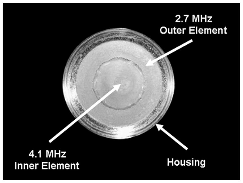
Photograph of the prototype dual-focus therapeutic ultrasound transducer (DFTUT).
RESULTS
Electrical impedance measurement
Figure 9 shows the measured electrical impedance of the water-loaded DFTUT with an impedance analyzer (4294A Impedance Analyzer; Agilent, Santa Clara, CA, USA). Two peaks of the impedance plots are seen in series. One is for the outer element at a lower frequency and the other for the inner element at a higher frequency. The anti-resonance frequencies for each element were 42 Ω at 2.7 MHz and 93 Ω at 4.2 MHz, respectively. The driving frequencies of DFTUT were determined given a maximal peak of the transmit response resulting in a peak pressure value in the hydrophone measurement. The 2.7 MHz and 4.1 MHz frequencies for outer and inner elements yielded the highest pressures and their impedances were 40 Ω and 60 Ω, respectively.
Fig. 9.

Measured electrical impedance of the dual-focus therapeutic ultrasound transducer (DFTUT) with a water load. There are two impedance peaks in series for outer and inner elements, respectively.
Transmit response measurement
A needle hydrophone (HPM04/1; Precision Acoustics Ltd, Dorchester, UK) was used to measure the transmit response of the DFTUTas shown in Figure 10. A function generator (33250A; Agilent, Santa Clara, CA) capable of generating a 2-cycle pulsed wave (PW) signal at frequencies at 4.1 MHz and 2.7 MHz was connected to a 50 dB RF power amplifier (325LA; ENI Co., Santa Clara, CA, USA) resulting in 32 Vpp input voltage and subsequently used to activate the DFTUT. The distance between the DFTUT and the hydrophone was varied from 5 mm to 40 mm via a controller (6000ULN; Burleigh Instruments Inc., Fishers, NY, USA) with a XYZ translation stage driven by a piezoelectric stepper motor (IW-700 Series Inchworm Motor; Burleigh Instruments Inc., Fishers, NY, USA). Signals received by the hydrophone were amplified by 25 dB (Hydrophone Booster Amplifier; Precision Acoustics Ltd., UK), measured with a digital oscilloscope (LC534; LeCroy, Chestnut Ridge, NY, USA) with eight-bit analog to digital converter (ADC) card and recorded by a computer with a data acquisition board.
Fig. 10.

Experimental set-up for measurement of the transmit response, depth-of-focus (DOF) and lateral beam-width of the dual-focus therapeutic ultrasound transducer (DFTUT) by using a hydrophone: (a) a photograph and (b) a schematic diagram.
Figure 11 shows the measured transmit frequency domain response for the DFTUT at various depths along the axial direction. Its magnitude at different depths was observed to be proportional to the amount of energy contributed by the two elements. In the near field as shown in Figure 11a, 4.1 MHz frequency component of the inner element was higher than 2.7 MHz frequency and this ratio was reversed at far field as shown in Figure 11b, c, and d. The distances between a hydrophone and the transducer in Figure 11a through d were 18 mm, 23 mm, 28 mm and 33 mm, respectively.
Fig. 11.

Frequency domain plots of the measured transmit response along the axial direction: (a) 18 mm, (b) 23 mm, (c) 28 mm and (d) 33 mm in depth.
DOF/lateral beamwidth/sidelobe measurement
The identical experimental set-up as described in Figure 10 was used to measure the −6 dB DOF and the −6 dB lateral beamwidth of the DFTUT. The swept range for the hydrophone was from 5 mm to 40 mm in the axial direction and from −5 mm to 5 mm in the lateral direction. Eight sets of lateral beam profiles were recorded at 2 mm intervals within the −6 dBDOF, i.e., 15 mm to 30 mm. The measured −6 dB DOF was approximately 14.5 mm as shown in Figure 12a. Figure 12b shows measured −6 dB lateral beamwidths approximately 15 mm to 30 mm in the −6 dB DOF, however, a dip was observed around 25 mm.
Fig. 12.
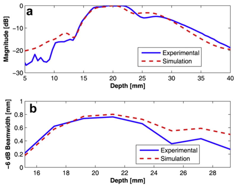
Simulated and measured data for the dual-focus therapeutic ultrasound transducer (DFTUT) using a hydrophone: (a) an axial beam profile with depth-of-focus (DOF) and (b) −6 dB overall lateral beamwidth within the −6 dB DOF.
There are several possibilities that may explain this phenomenon including a difference in the delivered energies between the near field and far field and misalignment between two elements during the fabrication process, error of radius of each curvature and the offset between two elements during pressed focusing. Because the most likely cause may be the result from the difference in delivered energies due to the impedance and dimension of each element, a modified simulation was conducted by reducing the amplitude of the outer element signal to half of the inner element considering the amplitude of the dip in Figure 12a and including geometrical errors of the prototype transducer such as dimension and the depth offset between two elements. However, it appeared that the most significant change came from the amplitude difference between the two frequencies. When the amplitude of low frequency component was decreased to half of the high frequency component in the input signal, the resulted curve was remarkably similar as shown in Figure 12a and b. Although the location of the dip point is lower than measured data, the patterns were very similar. Thus, compared with the same amplitude results in Figure 5, it is clear that the output power of each element may affect the performance of the DFTUT. It seems that this phenomenon might be caused by the electrical impedance mismatch due to dimension and driving frequency for each element. The alignment accuracy may be also critical during the fabrication process. These results showed that the extended −6 dB DOF could be obtained although it was not possible to maintain a constant lateral beamwidth throughout the DOF, which likely was caused by the difference in the delivered energies as illustrated in Figure 12a. This unbalance in emitted power between the two elements may be minimized through more optimized transducer design carefully considering the impedance match, frequency and dimension of each element. Figure 13 shows the measured lateral beam profiles at 20 mm and 22 mm depths with simulation data under the condition that is similar to Figure 12. The measured and the simulated sidelobe level were −11.3 dB and −13.4 dB, respectively. The discrepancies between the two data sets might be attributed to the limited dynamic range of the eight-bit ADC card.
Fig. 13.
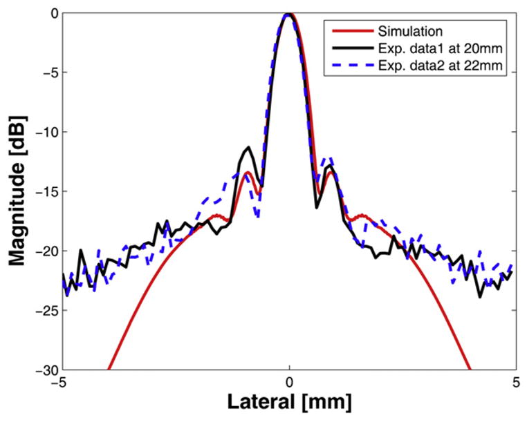
Simulated and measured lateral beam pattern for the dual-focus therapeutic ultrasound transducer (DFTUT): the simulated (red-solid) and the measured data at 20 mm (black-solid) and at 22 mm in depth (blue-dashed).
Lesion formation with in vitro target
A teston soft biologic tissue lesionformation was conducted to verify the performance of the device. The experimental arrangement was nearly identical to what was described for the hydrophone test as shown in Figure 14a. A fresh whole beef liver, obtained from the slaughterhouse within 12 h after excision from the animal, was sliced with 5 cm × 5 cm × 5 cm in size. The specimen was not degassed and placed in a degassed water bath. The target distance from the surface of the transducer was controlled to be approximately 10 mm with a sample holder.
Fig. 14.

Cross-section of a piece of beef liver after high-intensity focused ultrasound (HIFU) sonication with dual-focus therapeutic ultrasound transducer (DFTUT). The arrow indicates the HIFU exposure direction. (a) A schematic diagram to generate (b) the ablated lesion in a beef liver.
The amplitude of the signal used to excite the transducer was increased to 140 Vpp with a 55 dB power amplifier (A300; ENI Co., Santa Clara, CA, USA) resulting in an estimated 6.1 MPa peak positive pressure. Figure 14b shows the ablated tissue lesion of a beef liver with 140 Vpp applied voltage for 30 s. The lesion size was approximately 25 mm in length and tapering width from approximately 8 mm. This tapering was likely due to the difference in the delivered energies between the two elements in the DFTUT. The coagulated region in the axial and lateral direction was wider than the results obtained by hydrophone measurements in Figure 12, which may be related to the thermal conduction due to high ambient temperature based on extended exposure time approximately 30 s (ter Haar et al. 1989).
Note that the coagulated lesion in Figure 14 was formed in front of the geometrical focal depths of DFTUT and moved toward the surface of the tissue. This prefocal heating may be explained by the nonlinear distortion of the ultrasound wave in the tissue. Another reason may be the changed property of the ablated-tissue resulting in unusual attenuation coefficients during high temperature HIFU sonication such as thermal lens effect (Chen et al. 1997; Connor and Hynynen 2002; Hallaj et al. 2001; Melodelima et al. 2004; ter Haar et al. 1989).
DISCUSSION AND CONCLUSION
In this article, we proposed a method to increase the volume of tissue lesion in the axial direction by extending the DOF with DFTUT targeting the treatment of tumors. The basic concept of this method is partially overlapping two DOFs generated by spatially aligned two coaxial elements, which have different center frequencies. To extend the DOF maintaining the uniformity in the axial and the lateral beam profiles, transducer design must be optimized considering the frequency, the dimension of each element and the relative geometric focus offset. In the sound field simulation, the 4.1 MHz and 2.7 MHz center frequencies for the inner and outer elements and 5.24 mm of the relative geometric focus offset between two focal depths could provide extended −6 dB DOF approximately 3.1 to 3.5 times larger than a conventional transducer of the same diameter while maintaining a relatively uniform lateral beamwidth.
The proper relative geometric focus offset can be determined by the cross point of two intensity plots at which the intensity sum of two overlapped zones belonging to inner and outer elements should be higher than −6 dB. However, in reality, because the slope of each curve in the overlapped zone is not symmetric, a higher value may be required. In this study, −2 dB point from the maximal intensity was chosen and, thus, two focal depths were separated by 5.24 mm. These results demonstrate that the length of the extended DOF can be changed by controlling the relative geometric focus offset. The lateral beamwidth was similar to other transducers as shown in Table 2 because this method is mainly focused on the extended DOF in axial direction. The side-lobe level of DFTUT also can be varied by changing the physical dimensions of the two elements.
In this study, an approach in transducer fabrication in which two elements were excited simultaneously with a single electrode by a single transmitter instead of two separated electrodes was introduced to extend the DOF. The prototype transducer based on this design could provide extended DOF resulting in a longer lesion. In this configuration, electrical impedance matching for both elements and the total input impedance may be important for balancing the output power. The length of the extended −6 dB DOF with a hydrophone measurement shows 14.5 mm although there was a dip around 25 mm. One of the possible reasons may be the difference in delivered energies between these two elements due to nonoptimized electrical impedance of the prototype transducer. In sound field simulation, when the amplitude of the low frequency is lower than the high frequency components, the final output DOF shows a trend similar to the measured data with a nonuniform intensity contour. This observation seems to suggest that output power unbalance may the primary culprit of this behavior and it may be solved by better matching electrical impedances or by changing the excitation parameters.
Several fabrication issues such as a depth offset and alignment errors during the assembly of the two elements can be solved with the use of proper fixtures. Additionally, under similar driving conditions, the ultrasound intensity along the elongated DOF produced by the DFTUT may be lower than a single-focused transducer, so higher driving power may be required to obtain the same treatment effect. The bioheat transfer simulation results show that the DFTUT can generate a temperature up to 83°C under the current driving conditions within the extended DOF and the lesion formation test with a piece of beef liver shows a lesion of approximately 25 mm length and 8 mm width with a tapering shape, which may come from the relatively lower intensity of the outer element. Because the temperature distribution is not sufficient to estimate coagulated lesion size, thermal dose simulation was performed and the 240-min region was approximately 1 mm wide and 12 mm long.
The simulated temperature profile shows the lesion of a maximal 5 mm width and 28 mm length with different temperature distribution. In the in vitro experiment, although the whole region changed color due to HIFU sonication was approximately 8 mm wide and 25 mm long, there was a gradual color variation from the center to the outer zone. The more coagulated white colored center lesion was approximately 2 mm in width and 11 mm in length, which corresponded to the thermal dose simulation results that showed a lesion of 1 mm width and 12 mm length at 240 min. This thermal lesion expansion may be explained by the thermal conduction due to high ambient temperature resulted from extended exposure time for approximately 30 s. The changed attenuation/absorption coefficients during HIFU sonication might increase the focal temperature (Meaney et al. 1998). Nonlinear wave distortion and cavitation might also play a role in the nondegassed target and, thus, resulted in an expanded lesion (Connor and Hynynen 2002; He et al. 2005; Liu et al. 2006). Because the classical bioheat/thermal dose simulation and hydrophone measurement do not include these factors, significant discrepancy between the simulation and experiment may result (Connor and Hynynen 2002; Hallaj et al 2001).
Increasing the amplitude of the outer element excitation was necessary to obtain a more regular lesion shape to compensate the increased attenuation compensation for deep targets. Currently, 20 W electrical power input to the prototype transducer was almost close to its maximal capability to achieve lesion ablation. In the frequency mixed input signal, the amplitude of low frequency signal for the outer element should be approximately doubled to achieve proper intensity compensation based on simulation results. This compensation may be over the power limit of the current prototype transducer.
In the in vitro experiment, the target was mounted in the water and there was approximately a 10 mm water standoff. Among them, 6 mm was the distance from the center of the transducer to the front of the transducer’s housing and 4 mm was the distance from the front of the housing to the target. In this set-up, the −6 dB pressure level measured by a hydrophone was considered expecting the proximal point of the lesion might be start few millimeters beneath from the surface of the target. However, the lesion was expanded to larger than that predicted by the −6 dB intensity contour and was formed close to the surface of the target, i.e., the proximal point of the lesion was approximately 1 mm below of the surface. One of the potential reasons causing this prefocal heating was the thermal conduction related to an extended sonication time. The changed attenuation/absorption coefficient and nonlinear distortion of the ultrasound wave in the ablated lesion during HIFU sonication may cause formation of the lesion in front of the geometrical focus, which may be similar to thermal lens effect (Connor and Hynynen 2002; Garnier et al. 2008; ter Haar et al. 1989). We believe that if the two geometric focal depths of the proposed transducer are long enough, the lesion may be formed deeper in the target despite the above reasons.
These results demonstrate the feasibility of the DFTUT to extend DOF resulting in a broad tissue lesion in the axial direction. This technique may be useful for treatment of the large tumors especially deep-seated tumors. The fabrication process for the DFTUT may be further improved to optimize the performance of such a device.
Acknowledgments
The authors would like to thank Dr. Hyung Ham Kim for help with the hydrophone measurements. The authors are grateful to Mr. Jay Williams for his expert advice and valuable discussions. The work has been partially supported by NIH grant # P41-EB2182.
References
- Burckhardt CB, Hoffmann H, Grandchamp PA. Ultrasound axicon: A device for focusing over a large depth. J Acoust Soc Am. 1973;54:1628–1630. [Google Scholar]
- Chen L, ter Haar GR, Hill CR. Influence of ablated tissue on the formation of high-intensity focused ultrasound lesions. Ultrasound Med Biol. 1997;23:921–931. doi: 10.1016/s0301-5629(97)00016-1. [DOI] [PubMed] [Google Scholar]
- Connor CW, Hynynen K. Bio-acoustic thermal lensing and nonlinear propagation in focused ultrasound surgery using large focal spots: a parametric study. Phys Med Biol. 2002;47:1911–1928. doi: 10.1088/0031-9155/47/11/306. [DOI] [PubMed] [Google Scholar]
- Damianou C, Hynynen K. The effect of various physical parameters on the size and shape of necrosed tissue volume during ultrasound surgery. J Acoust Soc Am. 1994;95:1641–1649. doi: 10.1121/1.408550. [DOI] [PubMed] [Google Scholar]
- Damianou CA, Sanghvi NT, Fry FJ, Maass-Moreno R. Dependence of ultrasonic attenuation and absorption in dog soft tissues on temperature and thermal dose. J Acoust Soc Am. 1997;102:628–634. doi: 10.1121/1.419737. [DOI] [PubMed] [Google Scholar]
- Damianou CA, Hynynen K, Fan X, Wan H. Evaluation of Accuracy of a theoretical model for predicting the necrosed tissue volume during focused ultrasound surgery. IEEE Trans Ultrason Ferroelectr Freq Control. 1995;42:182–187. [Google Scholar]
- Daum DR, Hynynen K. A 256-element ultrasonic phased array system for the treatment of large volumes of deep-seated tissue. IEEE Trans Ultrason Ferroelectr Freq Control. 1999;46:1254–1268. doi: 10.1109/58.796130. [DOI] [PubMed] [Google Scholar]
- Daum DR, Smith NB, King R, Hynynen K. In vivo demonstration of noninvasive thermal surgery of the liver and kidney using ultrasound phased array. Ultrasound Med Biol. 1999;25:1087–1098. doi: 10.1016/s0301-5629(99)00053-8. [DOI] [PubMed] [Google Scholar]
- Do-Huu JP, Hartemann P. Deep and local heating induced by an ultrasound phased array transducer. IEEE Ultrason Symp. 1982:735–738. [Google Scholar]
- Ebbini ES, Cain CA. Multiple-focus ultrasound phased-array pattern synthesis: Optimal driving-signal distributions for hyperthermia. IEEE Trans Ultrason Ferroelectr Freq Control. 1989;36:540–548. doi: 10.1109/58.31798. [DOI] [PubMed] [Google Scholar]
- Fjield T, Fan X, Hynynen K. A parametric study of the concentric-ring transducer design for MRI guided ultrasound surgery. J Acoust Soc Am. 1996;100:1220–1230. doi: 10.1121/1.416217. [DOI] [PubMed] [Google Scholar]
- Furusawa H, Namba K, Nakahara H, Tanaka C, Yasuda Y, Hirabara E, Imahariyama M, Komaki K. The evolving non-surgical ablation of breast cancer: MR guided focused ultrasound (MRgFUS) Breast Cancer. 2007;14:55–58. doi: 10.2325/jbcs.14.55. [DOI] [PubMed] [Google Scholar]
- Garnier C, Lafon C, Dillenseger JL. 3-D modeling of the thermal coagulation necrosis induced by an interstitial ultrasonic transducer. IEEE Trans Biomed Eng. 2008;55:833–837. doi: 10.1109/TBME.2007.914543. [DOI] [PMC free article] [PubMed] [Google Scholar]
- Hallaj IM, Cleveland RO, Hynynen K. Simulations of the thermo-acoustic lens effect during focused ultrasound surgery. J Acoust Soc Am. 2001;109:2245–2253. doi: 10.1121/1.1360239. [DOI] [PubMed] [Google Scholar]
- He PZ, Shou WD, Duan SM, Xia RM. Dual-frequency high-intensity focused ultrasound (HIFU) accelerating therapy. Proc IEEE Eng Med Biol. 2005:213–216. doi: 10.1109/IEMBS.2005.1616381. [DOI] [PubMed] [Google Scholar]
- Jensen JA, Svendsen NB. Calculation of pressure fields from arbitrarily shaped, apodized and excited ultrasound transducers. IEEE Trans Ultrason Ferroelectr Freq Control. 1992;39:262–267. doi: 10.1109/58.139123. [DOI] [PubMed] [Google Scholar]
- Lin WL, Liang TC, Yen JY, Liu HL, Chen YY. Optimization of power deposition and a heating strategy for external ultrasound thermal therapy. Med Phys. 2001;28:2172–2181. doi: 10.1118/1.1406516. [DOI] [PubMed] [Google Scholar]
- Liu HL, Chen WS, Chen JS, Shih TC, Chen YY, Lin WL. Cavitation-enhanced ultrasound thermal therapy by combined low- and high-frequency ultrasound exposure. Ultrasound Med Biol. 2006;32:759–767. doi: 10.1016/j.ultrasmedbio.2006.01.010. [DOI] [PubMed] [Google Scholar]
- Meaney PM, Clarke RL, ter Haar GR, Rivens IH. A 3-D finite-element model for computation of temperature profiles and regions of thermal damage during focused ultrasound surgery exposures. Ultrasound Med Biol. 1998;24:1489–1499. doi: 10.1016/s0301-5629(98)00102-1. [DOI] [PubMed] [Google Scholar]
- Melodelima D, N’Djin WA, Parmentier H, Chesnais S, Rivoire M, Chapelon JY. Thermal ablation by high-intensity-focused ultrasound using a toroid transducer increases the coagulated volume. Results of animal experiments. Ultrasound in Med Biol. 2009;35:425–435. doi: 10.1016/j.ultrasmedbio.2008.09.020. [DOI] [PubMed] [Google Scholar]
- Melodelima D, Chapelon JY, Theillère Y, Cathignol D. Combination of thermal and cavitation effects to generate deep lesions with an endocavitary applicator using a plane transducer: Ex vivo studies. Ultrasound in Med Biol. 2004;30:103–111. doi: 10.1016/j.ultrasmedbio.2003.09.005. [DOI] [PubMed] [Google Scholar]
- Murat FJ, Poissonnier L, Rabilloud M, Belot A, Bouvier R, Rouviere O, Chapelon JY, Gelet A. Mid-term results demonstrate salvage high-intensity focused ultrasound (HIFU) as an effective and acceptably morbid salvage treatment option for locally radio recurrent prostate cancer. Eur Urol. 2009;55:640–649. doi: 10.1016/j.eururo.2008.04.091. [DOI] [PubMed] [Google Scholar]
- Nyborg WL. Heat generation by ultrasound in a relaxing medium. J Acoust Soc Am. 1981;70:310–312. [Google Scholar]
- Owen NR, Bouchoux G, Seket B, Murillo-Rincon A, Merouche S, Birer A, Paquet C, Delabrousse E, Chapelon JY, Berriet R, Fleury G, Lafon C. In vivo evaluation of a mechanically oscillating dual-mode applicator for ultrasound imaging and thermal ablation. IEEE Trans Biomed Eng. 2010;57:80–92. doi: 10.1109/TBME.2009.2023994. [DOI] [PubMed] [Google Scholar]
- Parker KJ. Ultrasonic attenuation and absorption in liver tissue. Ultrasound Med Biol. 1983;9:363–369. doi: 10.1016/0301-5629(83)90089-3. [DOI] [PubMed] [Google Scholar]
- Patel PR, Luk A, Durrani A, Dromi S, Cuesta J, Angstadt M, Dreher MR, Wood BJ, Frenkel V. In vitro and in vivo evaluations of increased effective beam width for heat deposition using a split focus high-intensity ultrasound (HIFU) transducer. Int J Hyperthermia. 2008;24:537–549. doi: 10.1080/02656730802064621. [DOI] [PMC free article] [PubMed] [Google Scholar]
- Patterson MS, Foster FS. Acoustic fields of conical radiators. IEEE Trans Ultrason Ferroelectr Freq Control. 1982;SU-29:83–92. [Google Scholar]
- Pennes HH. Analysis of tissue and arterial blood temperatures in the resting human forearm. J Appl Physiol. 1948;1:93–122. doi: 10.1152/jappl.1948.1.2.93. [DOI] [PubMed] [Google Scholar]
- Sapareto SA, Dewey WC. Thermal dose determination in cancer therapy. Int J Radiat Oncol Biol Phys. 1984;10:787–800. doi: 10.1016/0360-3016(84)90379-1. [DOI] [PubMed] [Google Scholar]
- Sasaki K, Azuma T, Kwabata KI, Shimoda M, Kokue EI, Umemura SI. Effect of split-focus approach on producing larger coagulation in swine liver. Ultrasound Med Biol. 2003;29:591–599. doi: 10.1016/s0301-5629(02)00792-5. [DOI] [PubMed] [Google Scholar]
- Seip R, Sanghvi NT, Umemura SI. Comparison of split-beam transducer geometries and excitation configurations for transrectal prostate HIFU treatments. IEEE Ultrason Symp. 2001:1343–1346. [Google Scholar]
- Shung KK. Diagnostic ultrasound: Imaging and blood flow measurements. Boca Raton FL: CRC Press; 2006. [Google Scholar]
- Stepanishen PR. The time-dependent force and radiation impedance on a piston in a rigid infinite planar baffle. J Acoust Soc Am. 1971;49:841–849. [Google Scholar]
- ter Haar GR. Intervention and therapy. Ultrasound Med Biol. 2000;26:S51–S54. doi: 10.1016/s0301-5629(00)00164-2. [DOI] [PubMed] [Google Scholar]
- ter Haar GR, Sinnett D, Rivens I. High-intensity focused ultrasound-A surgical technique for the treatment of discrete liver tumours. Phys Med Biol. 1989;34:1743–1750. doi: 10.1088/0031-9155/34/11/021. [DOI] [PubMed] [Google Scholar]
- Trzaskos CR, Young JD. Compound focus ultrasonic transducer. 4,659,956. US Patent. 1987
- Tupholme GE. Generation of acoustic pulses by baffled plane pistons. Mathematika. 1969;16:209–224. [Google Scholar]
- Vaezy S, Andrew M, Kaczkowski P, Crum L. Image-guided acoustic therapy. Annu Rev Biomed Eng. 2001;3:375–390. doi: 10.1146/annurev.bioeng.3.1.375. [DOI] [PubMed] [Google Scholar]
- Wan H, VanBaren P, Ebbini ES, Cain CA. Ultrasound surgery: Comparison of strategies using Phased array systems. IEEE Trans Ultrason Ferroelectr Freq Control. 1996;43:1085–1098. [Google Scholar]
- Wu JSJ, Sanghvi NT, Phillips MH, Kumetsov M, Foster RS, Bihrle R, Gardner TA, Umemura SI. Experimental studies of using of split beam transducer for prostate cancer therapy in comparison to single beam transducer. IEEE Ultrason Symp. 1999:1443–1446. [Google Scholar]