Abstract
We have previously described miniature 2D array transducers integrated into a Cook Medical, Inc. vena cava fi ter deployment device. While functional, the fabrication technique was very labor intensive and did not lend itself well to efficient fabrication of large numbers of devices. We developed two new fabrication methods that we believe can be used to efficiently manufacture these types of devices in greater than prototype numbers. One transducer consisted of 55 elements operating near 5 MHz. The interelement spacing is 0.20 mm. It was constructed on a flat piece of copper-clad polyimide and then wrapped around an 11 French catheter of a Cook Medical, Inc. inferior vena cava (IVC) filter deployment device. We used a braided wiring technology from Tyco Electronics Corp. to connect the elements to our real-time 3D ultrasound scanner. Typical measured transducer element band width was 20% centered at 4.7 MHz and the 50 Ω round trip insertion loss was -–82 dB. The mean of the nearest neighbor cross talk was –37.0 dB.
The second method consisted of a 46-cm long single layer flex circuit from MicroConnex that terminates in an interconnect that plugs directly into our system cable. This transducer had 70 elements at 0.157 mm interelement spacing operating at 4.8 MHz. Typical measured transducer element bandwidth was 29% and the 50 Ω round trip insertion loss was –83 dB. The mean of the nearest neighbor cross talk was –33.0 dB.
Keywords: 2D array transducer, real-time 3D imaging, vena cava filter
I. INTRODUCTION
Fluoroscopy is the imaging modality of choice for the guidance of interventional medical devices, such as inferior vena cava (IVC) filters and abdominal aortic aneurysm (AAA) stent grafts. While fluoroscopy has excellent visualization of these devices in the body, the 3D information is lost. Also, soft tissue structures are not so easily visualized. The use of potentially toxic x-ray contrast agents provides only a momentary glimpse of vascular structures. Commercial 2D ultrasound catheters may also be applied for device guidance. One group has reported the use of an AcuNav (Siemens, Mountain View, CA) ultrasound probe for the planning and guiding of an endovascular aneurysm repair (EVAR).1 This was combined with fluoroscopy. However, the authors noted that it was sometimes difficult to detect endoleaks due to the an unfavorable Doppler angle.1 This is an inherent prob lem with a side-scanning transducer.
Real-time 3D ultrasound enables continuous monitoring of these same structures before, during and after deployment. The development of real-time 3D intravascular ultrasound catheters has become an important research topic in several laboratories.2-6 However, integration of 3D ultrasound imaging arrays into the catheter deployment kits of interventional devices presents major challenges due to the requirement for potentially hundreds of active transducer channels to improve 3-D image quality and the severe fabrication difficulties in electrical connection to the submillimeter 2-D array elements. Figure 1 shows a schematic of an integrated 3D ultrasound transducer and the vena cava filter deployment catheter. The schematic shows the real–time 3D ultrasound pyramidal scan coming from the end of the device with the vena cava filter exiting the lumen.
FIG. 1.
Schematic of the integrated transducer and vena cava filter deployment device. Real-time 3D ultrasound pyramidal scan is directed out from the end of the catheter and is coaxial with the deployment of the vena cava filter.
Our previous fabrication methods for 3D intravascular ultrasound catheters relied onusing multiple MicroMiniature Ribbon Cables from W.L. Gore & Associates (Newark, DE).7 We have a great deal of experience and expertise in our laboratories using these cables making the electrical interconnections for our transducers.8-11 It was difficult to attach multiple (we used six) of these cables around the 12 French catheter lumen of the Cook device. We were limited in our interelement spacing (pitch) by the set spacing of the conductors to factors of 0.10 mm. There is also no integrated shielding and the individually-shielded cables are very stiff and even more difficult to attach to the catheter lumen than the cables without shielding.
In this paper, we describe two new fabrication processes based on different electrical interconnection schemes. The first uses a braided cabling technology from Tyco Electronics Corp. (Wilsonville, OR) to electrically connect the elements to our system cable. The second technique uses a 46 cm long flexible circuit from MicroConnex (Snoqualmie, WA) that terminates in an interconnect that plugs directly into our system cable. For each process, we fabricated the transducer and connected it to our ultrasound imaging system (Volumetrics Medical Imaging, Durham, NC) and made real-time 3D images.
II. METHODS
A. Real-time 3D ultrasound imaging
We used standard three dimensional (3D) phased-array beam-forming techniques to generate our real-time 3D images. Real-time 3D ultrasound was developed in our laboratories at Duke University by von Ramm and Smith12, 13 and first commercialized for cardiovascular applications by Volumetrics Medical Imaging, Inc. (VMI, Durham, NC). The Duke/VMI 3D system scans a 65°-120° pyramid with matrix array transducers of up to 500 active channels to produce 3D scans at rates up to 30 volumes/s using 16:1 receive mode parallel processing. Real-time display options include up to five image planes oriented at any desired angle, depth and thickness within the pyramidal scan as well as real-time 3D volume rendering, 3D pulse-wave Doppler and 3D color-flow Doppler. The VMI system uses an 8 bit analog-to-digital (A/D) converter on the detected data for a possible 48 dB of display dynamic range.
We used a VMI Model 1 scanner for this work. In our laboratories at Duke during the last few years, we have significantly modified the Volumetrics scanner to use our prototype 2-D arrays for applications such as real time 3D transesophageal imaging,10 laparoscopic imaging,9 intracardiac and intravascular imaging with catheter transducers8 at 5, 7, 10 and 15 MHz.2, 9 No new modifications were needed for the transducers described in this paper to run on the VMI Model 1 scanner.
B.Transducer design and fabrication
We modified a Cook Medical Inc. (Bloomington, IN) Günther Tulip™ vena cava filter deployment kit for our ring transducers. This commercial product uses an 8.5 Fr sheath (I.D) resulting in an approximately 11 French (O.D.) catheter to deploy the vena cava filter. This O.D. determined the transducer size. The vena cava filter is 50 mm long. With the need to image at least 60 mm in depth, we need to use frequencies below those typically used for intravascular ultrasound (IVUS). A further limitation is that the analog-receive filters in the VMI system have a top limiting frequency of 5 MHz. We designed our transducers to meet these constraints.
For the first fabrication process, the Tyco braided wiring cable included 64 signal wires along with individual ground wires for each signal wire and an overall metal braid to use as a shield against electronic pickup noise. For the first prototypes, we used the same flexible circuit we previously designed for the Gore MicroMiniature Ribbon Ca bles.7 This limited the transducer to 55 elements with an interelement spacing of 0.20 mm.
For the second process, we developed a totally new flexible circuit that is 46 cm long with traces on one side. Since we were not limited by the set spacing of the Micro Miniature Cables, we changed the interelement spacing to 0.157 mm, resulting in a 70 element transducer. The polyimide is 0.025 mm thick. The traces are 0.107 mm wide, 0.004 mm thick with 0.050 mm spaces. The backside of the polyimide is metallized to provide a ground return for the face of our transducer elements. Since the proximal end of our flexible circuit terminates in a connector layout that fits our system cable, no soldering is necessary.
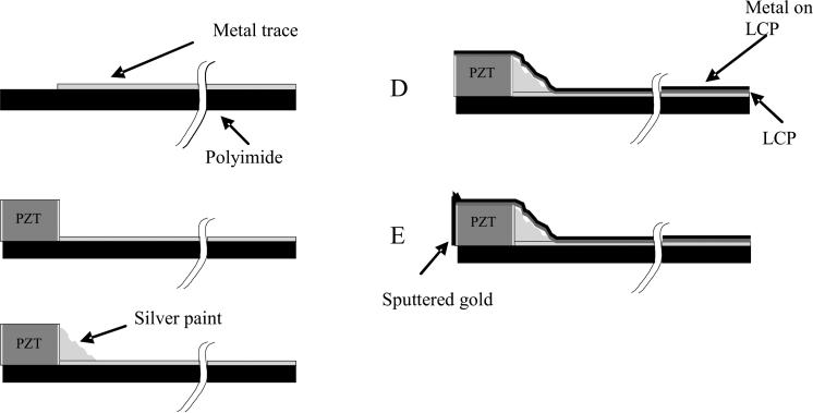
The construction of the transducer array itself is the same for each fabrication method. Figure 2 shows a schematic of the construction steps used to build the ring array transducers. It starts with a 0.025 mm thick metal clad polyimide flexible circuit. This substrate has a shelf area where there is no metal (Fig. 2A). A beam of PZT ceramic (TRS Technologies, Inc., State College, PA) was prepared that was 0.30 mm tall (thick), 0.18 mm wide and 11 mm long. This beam was attached to the polyimide with a low viscosity epoxy (Epo-Tek 301, Epoxy Technology, Billerica, MA) such that the beam was on its side (Fig. 2B). With the beam on its side, the electroded portion of the PZT is pointed in the forward direction. After attaching the PZT, silver paint (SPI Supplies®, West Chester, PA) was applied such that it contacted the bottom electrode of the PZT and the traces (Fig. 2C) on the polyimide. The transducer beam was then diced at the appropriate spacing and the whole device wrapped around a lumen with the same O.D. as the Cook lumen. A 0.012 mm thick layer of metallized liquid crystal polymer (LCP) supplied by MicroConnex was wrapped around the outer circumference of the PZT and polyimide substrate (Fig. 2D) and attached with epoxy (Hysol E-60NC epoxy potting compound). The LCP keeps the transducer in a cylindrical shape. The Hysol epoxy fills the kerfs so that there is an even surface on the front end of the transducer. We then sputter gold onto the face of the transducer and LCP. This sputtering also makes contact to the metallized layer on the underside of the flexible circuit for the long flex method. After fabricating the transducer and attaching it to the catheter lumen, we sent it to Tyco for cabling. They attached the braided cable and soldered the electrical signal wires to the transducer flex circuit at the distal end and to another circuit board at the proximal end. The device was returned to us, the LCP attached and we attached the ground wires to the metallized LCP layer. A short piece of heat shrink (Advanced Polymers, Inc. Salem, NH) was attached to seal the LCP and cover the wiring.
FIG. 2.
Schematic of the steps in building the ring array transducers. We start with a metallized polyimide substrate (A) with an area without the metal to attach the PZT. We next attach the PZT beam (B) with nonconductive epoxy. After the epoxy cures, silver paint is used to connect the back electrode of the PZT with the metal trace (2C). The PZT is then diced and wrapped around a lumen. An 0.012 mm thick layer of liquid crystal polymer (LCP) is wrapped around the outer circumference of the PZT and polyimide substrate (2D). This LCP layer is metallized with gold (shown in black) on one side only, the outer side, so that it does not risk shorting the traces together. A layer of gold is sputtered on the face of the elements and connected to the gold on the outside of the LCP (2E).
For the long flex circuit method, no cabling was required. The whole flex was wrapped around another lumen from Cook Medical, attached with the same Hysol epoxy and a long piece of heat shrink that covered the whole flex except the connector ends. For both transducers, the face of the elements was sealed with a layer of ultraviolet (UV) curing adhesive (Loctite 366, Loctite Corp.,Hatford, CT). Figure 3 shows a photograph of the long flex circuit.
FIG. 3.
Photograph of 46 cm long flex circuit.
III. RESULTS
A. 55-element array, Tyco-cabling assembly
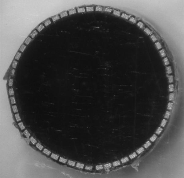
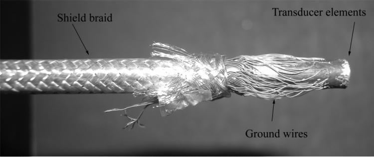
Figure 4 shows a photograph of the 55-element ring-array transducer after bonding to the LCP but before wiring and adding the electrical grounding. Figure 5 shows the com pleted device after wiring before the heat shrink was added.
FIG, 4.
Close-up of ring array after dicing and bonding to the LCP.
FIG. 5.
Close -up of wiring for 55-element transducer featuring Tyco-cable assembly. The overall shield braid increases the lumen O.D. to 13 French. After wiring, the extra shield braid is cut back and the exposed wires are sealed with 0.013 mm thick heat shrink (Advanced Polymers, Inc. Salem, NH).
We did pitch-catch measurements with adjacent elements in a water tank using a flat aluminum reflector 10 mm from the transducer face. We used a monopolar excitation pulse. Figure 6 shows a typical pulse (Fig. 6A) and spectrum (Fig. 6B) of this transducer. The center frequency is 4.7 MHz and the –6 dB band width is 20 %. Each figure has been averaged 10 times to reduce the noise. There is essentially no acoustic backing behind the PZT elements and no matching layer in this transducer. To measure the round-trip 50 Ω insertion loss, we loaded a single transmit element and a separate receive element with a 50 Ω load. We applied a 3 cycle, 4.8 MHz burst to the transmit element and measured the receive echo off an aluminum block in a water tank. The block was 2 mm away from the face of the transducer. We chose this distance to match what we could do with the long flex transducer. The result was –82 dB. The mean of the nearest neighbor cross talk is –37 dB.
FIG. 6.
Typical pulse and spectrum from the transducer featuring Tyco Electronics Corp. wiring assembly. Center frequency is 4.7 MHz and –6 dB bandwidth is 20%.
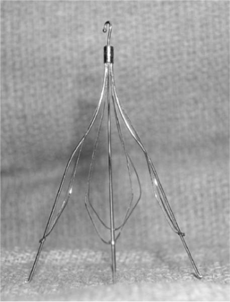
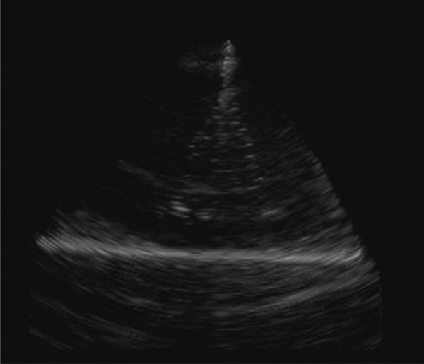
Figure 7 shows a photograph of the Cook Medical, Inc. Günther Tulip™ vena cava filter. The filter is made up of four main struts, each with finer ‘petals’ that give it the characteristic tulip shape. Figure 8 shows a real-time rendered view of the filter in a water tank made with the 55-element integrated transducer/deployment kit and the 3D scanner. The depth of scan is 8 cm and the full dynamic range has been logarithmically compressed to make the target brighter. We clearly see the main struts of the filter in the rendered image but the thinner wires that give this filter its tulip shape are not readily apparent.
FIG. 7.
Photograph of Cook Medical, Inc. vena cava filter.
FIG. 8.
Real-time, 3D-rendered view of Cook Medical, Inc. vena-cava filter made with 55-element ring-array transducer and Tyco Electronics Corp. wiring assembly. Depth of scan is 8 cm and the full dynamic range has been logarithmically compressed to make the target brighter.
B. 70-element array, flex-circuit assembly
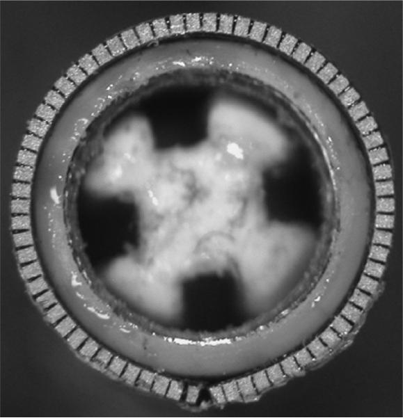
Figure 9 shows a close up of the front of the 5 MHz, 70-element ring array transducer constructed on the 46 cm long flex circuit. The elements have been diced and the transducer bonded to the catheter lumen with the LCP.
FIG. 9.
Close-up photograph of face of 70-element transducer built on a 46-cm long flexible circuit.
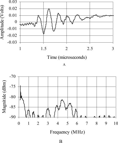
Figure 10 shows a typical pulse (Fig. 10A) and spectrum (Fig. 10B) of this transducer. We used the same pitch-catch set up for collecting these figures as described in figure 6. Each figure has been averaged 10 times to reduce the noise. The center frequency is 4.8 MHz and the –6 dB bandwidth is 29 %. This transducer also has no acoustic backing behind the PZT elements and no matching layer. We used the same technique as described for the Tyco wiring to measure the 50 Ω insertion loss and the result was –83 dB. Due to the long signal ring down, we could not get the aluminum block closer than 2.0 mm from the transducer. The mean of the nearest neighbor cross talk is – 33 dB.
FIG. 10.
Typical pulse and spectrum from transducer featuring 46-cm flexible circuit assembly. Center frequency is 4.8 MHz and –6 dB band width is 29%.
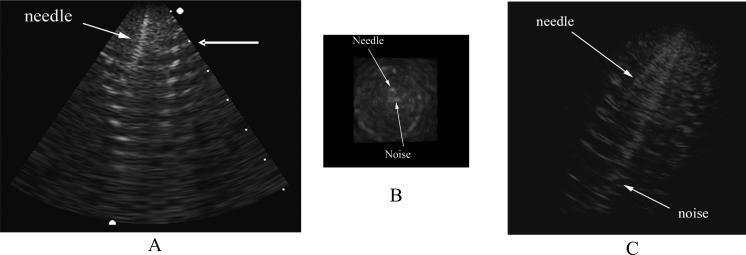
The 70-element array was inserted into the lumen of a Dacron vascular graft. Figure 11 shows a 7 cm deep long axis B-scan (Fig. 11A), a simultaneous C-scan (Fig. 11B) and a simultaneous real-time 3D rendered image (Fig. 11C) of the graft made with the-70 element transducer. The C-scan is taken at the depth indicated by the arrow in the right of figure 11 A. Also in the image, you can see a needle that was inserted through the catheter lumen and into the graft. While figures 11A and 11B are on a linear scale, figure 11C was logarithmically compressed to increase the brightness of the targets in the rendered view.
FIG. 11.
7-cm deep B-scan (A) with simultaneous C-scan (B) and rendered image (C) of an aortic aneurysm graft with a needle inserted out the lumen of the catheter and into the graft. The C-scan is made at the depth indicated by the arrow in the right of A. The rendered image (C) has been logarithmically compressed to increase the brightness of the targets. A and B are displayed on a linear scale.
V. DISCUSSION
We have developed two new fabrication techniques for building 2D ring arrary transducers. At this point, we have more experience with the Tyco Electronics Corp. wiring assembly method than with the 46 cm long flex circuits from MicroConnex. The transducers wired with the Tyco assemblies were slightly more sensitive but took longer to fabricate than the long flex transducers. The 50 Ω insertion loss data is high for both transducers. However, due to the long ring down of the transmit pulse using the long flex, we could not get the reflector closer than 2.0 mm. At this distance, we expect to see significant diffractive losses with such small elements. It is encouraging that both cables show a similar number, showing that the long flex circuit is a competitive technology with the Tyco wiring for construction. While we were only dealing with prototypes, it should also be noted that the transducer cost for developing the long flex transducers was more than a factor of 10 less than the Tyco cable assembly. This does not include the work done by our lab, but it should be noted that the Tyco assembly required further soldering of the ground wires onto the LCP so there was more labor in our lab for creating these transducers than for the longer flex circuits.
Figures 6 and 10 show a typical pulse for each transdcuer described. These appear similar to our previously-reported results.7 In each case, we can see a slight ramping in the time-based signal. For the Tyco assembly (Fig. 6A), the ramp has a negative slope. For the long flex assembly, the slope is positive. In each case, the cause is a low-frequency sinusoidal signal that we cannot isolate from our desired signal in this set up. It shows up clearly in the spectrum as a sharp peak around 300 KHz.
We can see in figure 11 that there is more electronic pick-up noise in the image made with the 46 cm long flex circuit. We believe this is due to the grounding scheme and can be fixed by adding more metal to the sputtered ground electrode and doing a better job of connecting the ground plane on the back of the flex to the ground traces that connect to our system cable. We were able to improve the noise in the images by improving this ground conncection but, unfortunately, tore the flex circuit while handling the transducer before we could record any images this way. We will improve strain relief in future devices to prevent this kind of tearing.
The small number of 2D elements used in these transducers limits the overall signal strength of the final device. While adding acoustic matching layers to the front of the the piezoelectric elements will improve this, other approaches need to be considered. Active receive circuitry to drive the cabling integrated into the device would improve the signal-to-noise ratio by about 20 dB.14 This approach is described by several groups.3-6 The use of multilayer piezoelectric elements also can help with transmit efficiency and driving the cable in receive.15 While active components can be integrated into either flex circuit easily, they provide an increase in cost. Custom circuits would have to be designed and fabricated to not increase the over all size of the device. This a very good solution to the problem and should be considered for any final clinical device but it is beyond the means of this group at this time. Multilayer piezoelectrics would also increase the cost but would not change the size of the device. We do have expertise in this area and will consider pursuing this as future work.
We did not take full advantage of the Tyco wiring assembly's 64 signal wires. We need a new flex circuit with 64 traces with an interelement spacing of 0.171 mm. However, for these first prototypes, we decided that keeping the spacing at 0.20 mm would make soldering easier. Not having to solder or design around soldering processes is an advantage of a customized long flex circuit. Future work will also include adding backing and matching layers to these transducers to improve sensitivity and bandwidth.
ACKNOWLEDGMENT
This research was supported by NIH grant HL089507. The authors would like to thank Cook Medical, Inc. for in kind support.
REFERENCES
- 1.Eriksson M-O, Wanhainen A, Nyman R. Intravascular ultrasound with a vector phased-array probe (AcuNav) is feasible in endovascular abdominal aortic aneurysm repair. Acta Radiologica. 2009;50:870–875. doi: 10.1080/02841850902912010. [DOI] [PubMed] [Google Scholar]
- 2.Light ED, Smith SW. Two dimensional arrays for real time 3D intravascular ultrasound. Ultrasonic Imaging. 2004;26:115–128. doi: 10.1177/016173460402600204. [DOI] [PubMed] [Google Scholar]
- 3.Degertekin FL, Guldiken RO, Karaman M. Annular-ring CMUT arrays for forward-looking IVUS: transducer characterization and imaging. IEEE Trans Ultrason Ferroelec Freq Contr. 2006;53:474–482. doi: 10.1109/tuffc.2006.1593387. [DOI] [PubMed] [Google Scholar]
- 4.Yeh DT, Oralkan O, Wygant IO, O'Donnell M, Khuri-Yakub BT. 3-D ultrasound imaging using a forward-looking CMUT ring array for intravascular/intracardiac applications. IEEE Trans Ultrason Ferroelec Freq Contr. 2006;53:1202–1211. doi: 10.1109/tuffc.2006.1642519. [DOI] [PubMed] [Google Scholar]
- 5.Wang Y, Stephens DN, O'Donnell M. Optimizing the beam pattern of a forward-viewing ring-annular ultrasound array for intravascular imaging. IEEE Trans Ultrason Ferroelec Freq Contr. 2002;49:1652–1664. doi: 10.1109/tuffc.2002.1159845. [DOI] [PubMed] [Google Scholar]
- 6.Wang Y, Stephens DN, O'Donnell M. Initial results from a forward-viewing ring-annular ultrasound array for intravascular imaging. Proc 2003 IEEE Ultrasonics Symp. 2003:212–215. doi: 10.1109/tuffc.2002.1159845. Cat. no.03CH37476C. [DOI] [PubMed] [Google Scholar]
- 7.Light ED, Smith SW. Real-time 3D ultrasound guidance of interventional devices. IEEE Trans Ultrason Ferro Freq Contr. 2008;55:2066–2078. doi: 10.1109/TUFFC.898. [DOI] [PMC free article] [PubMed] [Google Scholar]
- 8.Lee W, Smith SW. Miniaturized catheter 2D for real-time 3D intracardiac echocardiography. IEEE Trans Ultrason Ferroelec Freq Contr. 2004;51:1334–1346. doi: 10.1109/tuffc.2004.1350962. [DOI] [PubMed] [Google Scholar]
- 9.Light ED, Idriss SF, Sullivan KF, Wolf PD, Smith SW. Real-time 3D ultrasonic lapa roscopy. Ultrasonic Imaging. 2005;27:89–100. doi: 10.1177/016173460502700301. [DOI] [PubMed] [Google Scholar]
- 10.Pua EC, Idriss SF, Wolf PD, Smith SW. Real-time 3D transesophageal echocardiography. Ultrasonic Imaging. 2004;26:217–232. doi: 10.1177/016173460402600402. [DOI] [PubMed] [Google Scholar]
- 11.Light ED, Mukundan S, Wolf PD, Smith SW. Real-time 3D intracranial ultrasound. Ultrasound MedBiol. 2007;33:1277–1284. doi: 10.1016/j.ultrasmedbio.2007.02.004. [DOI] [PMC free article] [PubMed] [Google Scholar]
- 12.Smith SW, Pavy HE, von Ramm OT. High speed ultrasound volumetric imaging system part I: transducer design and beam steering. IEEE Trans Ultrason Ferroelec Freq Contr. 1991;32:100–108. doi: 10.1109/58.68466. [DOI] [PubMed] [Google Scholar]
- 13.von Ramm OT, Smith SW, Pavy HE. High speed ultrasound volumetric imaging system part II: parallel processing and display. IEEE Trans Ultrason Ferroelec Freq Contr. 1991;8:109–115. doi: 10.1109/58.68467. [DOI] [PubMed] [Google Scholar]
- 14.Emery CD, Smith SW. Improved signal-to-noise in hybrid 2-D arrays: experimental confirmation. Ultrasonic Imaging. 1997;19:93–111. doi: 10.1177/016173469701900201. [DOI] [PubMed] [Google Scholar]
- 15.Goldberg RL, Smith SW. Multilayer piezoelectric ceramics for two-dimensional array transducers. IEEE Trans Ultrason Ferroelec Freq Contr. 1994;41:761–771. doi: 10.1109/58.308512. [DOI] [PubMed] [Google Scholar]


