Abstract
Over the last decade microfluidics has created a versatile platform that has significantly advanced the ways in which micro-scale organisms and objects are controlled, processed and investigated, by improving the cost, compactness and throughput aspects of analysis. Microfluidics has also expanded into optics to create reconfigurable and flexible optical devices such as reconfigurable lenses, lasers, waveguides, switches, and on-chip microscopes. Here we present a new opto-fluidic microscopy modality, i.e., Holographic Opto-fluidic Microscopy (HOM), based on lensless holographic imaging. This imaging modality complements the miniaturization provided by microfluidics and would allow the integration of microscopy into existing on-chip microfluidic devices with various functionalities. Our imaging modality utilizes partially coherent in-line holography and pixel super-resolution to create high-resolution amplitude and phase images of the objects flowing within micro-fluidic channels, which we demonstrate by imaging C. elegans, Giardia lamblia, and Mulberry pollen. HOM does not involve complicated fabrication processes or precise alignment, nor does it require a highly uniform flow of objects within microfluidic channels.
OCIS codes. (090.1995) Digital holography, (180.0180) Microscopy
1. Introduction
Opto-fluidics is an emerging field that aims to merge the available toolset of optics and microfluidics to create more flexible and reconfigurable optical devices with novel functionalities that can be incorporated into lab-on-a-chip platforms [1–3]. The cost-effectiveness and compactness of lab-on-a-chip devices when combined with throughput and sensitivity have already enabled powerful solutions to a wide range of biomedical problems [4–13]. Opto-fluidic technologies would further enhance the performance and functionality of existing lab-on-a-chip platforms, and toward this end various opto-fluidic devices have been demonstrated including tunable lasers, lenses, waveguides and sensors [1–3,14,15]. Opto-Fluidic Microscopy (OFM) is another concept that came out of this emerging field, which aims to image objects flowing within a micro-fluidic channel without the use of any lenses [16–18]. In general, microfluidics enabled on-chip digital microscopy could especially be important for global health problems to assist diagnosis of disease (e.g., malaria or tuberculosis) in remote locations, and holds significant promise not only for point-of-care operation but also for telemedicine applications if a sufficiently high spatial resolution and throughput can be achieved on the same platform.
For this purpose, here we demonstrate a new method to conduct lensfree opto-fluidic microscopy, which relies on partially coherent digital in-line holography and multi-frame Pixel Super-Resolution [19] to create high-resolution on-chip images of the objects that are flowing within a micro-fluidic channel. In this approach, termed Holographic Opto-fluidic Microscopy (HOM), a spatially incoherent or partially coherent visible light source (quasi-monochromatic with a spectral bandwidth of 5-10 nm) illuminates the objects within a micro-fluidic channel as depicted in Fig. 1 . Within a few centimeters of free-space propagation, the illumination light picks up partial spatial coherence, the extent of which is sufficient to record lensfree in-line holograms of the objects flowing within the micro-fluidic channel. Each lensfree hologram is created by the interference of the scattered waves from the moving object with the background light, which acts a reference wave. When compared to standard lensfree in-line holograph approaches [20–22], the hologram recording geometry of Fig. 1, together with the use of partially coherent light (both spatially and temporally) emanating from an unusually large aperture (50-100µm) has several unique advantages such as simplicity to align and operate, significantly larger field-of-view, as well as reduced speckle and multiple-interference noise terms [19,23,24].
Fig. 1.
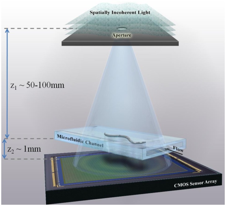
A schematic of the experimental set-up of Holographic Opto-fluidic Microscopy (HOM). The sample to be imaged flows within a micro-fluidic channel, due to either electro-kinetic or pressure driven motion, and is illuminated by partially coherent light emanating from a large aperture (~0.05-0.1mm) placed ~50-100 mm from the sample. The micro-channel is placed directly on a digital sensor array with no additional manipulation of the sensor-chip. (Not to scale.) The propagation distance between the aperture and the sample allows for spatial coherence to develop at the sample plane, and light scattered by the sample interferes with the background light to form a hologram on the sensor array plane.
Other opto-fluidic microscopy modalities have been previously reported. These earlier modalities require the objects of interest to be placed directly on the image sensor (i.e. within less than a few micrometers), and utilize either carefully fabricated sub-micron apertures [16,17], or multi-frame processing [18] to improve resolution beyond the sensor pixel size limitation. Direct contact imaging used in these existing opto-fluidic modalities unfortunately suffers from strong sensitivity to the exact distance of the object from the imaging sensor, which introduces uncontrolled image aberrations. The HOM technique, however, is not sensitive to the exact position of the object to be imaged, and in fact objects at different distances from the sensor can be simultaneously imaged since HOM permits digital recovery of the complex optical fields with sub-pixel resolution, enabling backward wave-propagation and depth focusing to be performed digitally. This feature generates both amplitude and phase images, which is of importance for biological samples in general. Furthermore, the insensitivity to the exact position of the objects in our approach allows the use of microfluidic channels with large cross-sections, enabling simultaneous imaging of objects of different sizes and alleviating the known problem of clogging in small channels, both of which offer important advantages for the design, fabrication and operation of our opto-fluidic microscope compared to existing approaches .
2. Operation principles of the holographic opto-fluidic microscope
A schematic of the HOM concept is shown in Fig. 1. A microfluidic channel (cross section ~80 µm X 1 mm) is placed directly on the top of a CMOS image sensor (Aptina MT9P031STC) with a 2.2 µm pixel pitch. The distance between the object and the sensor is 0.8-1.0 mm. The illumination is provided by a quasi-monochromatic incoherent light source (λ = 500nm, bandwidth ~5 nm) and a large pinhole of size 50-100 µm, which is placed approximately 5 cm away from the sensor. Despite the large pinhole size, the distance between the pinhole and the microfluidic channel allows spatial coherence of the illumination to develop at the object plane, such that the light scattered and diffracted by the object can interfere with unperturbed reference wave to produce a hologram at the sensor plane.
A single recorded in-line hologram can be processed using object-support constrained phase-retrieval algorithms [23,24] to produce amplitude and phase images with a resolution of ~1.5 µm. A limiting factor of the achievable resolution using a single hologram is undersampling due to the pixel pitch and the fact that our holographic setup operates with a unit fringe magnification. To circumvent this limitation, we use the flow inherent to microfluidic devices to capture multiple holograms of a given object as it flows in the microfluidic channel, due to either applied pressure or electro-kinetic flow. In general, these holograms will be shifted by a non-integer number of pixels compared to a reference hologram. Multiple frames which are sub-pixel shifted with respect to each other are then utilized through an iterative pixel super-resolution algorithm [19,25–28] to generate a higher resolution hologram which is compatible with all the measured shifted low-resolution holograms. The high-resolution hologram which has a smaller effective pixel size (e.g., a pixel size of 2.2 µm / 4 = 0.55 µm) is processed using the same iterative phase-retrieval algorithms, but now results in high-resolution microscope images, both in amplitude and in phase. It is important to note that the aim of our pixel super-resolution algorithm is to achieve finer sampling of the lensfree holograms, although the lower bound on the achievable resolution is still the diffraction limit, since the sensor-array can only capture the spatial frequencies which propagate to the sensor plane. To get closer to the diffraction limit, a key achievement could be further improvement of our detection signal to noise ratio, which can potentially be achieved by operating between 0.1 and 0.3 mm away from the active region of sensor chip. Optical super-resolution [29] in general aims to increase the available resolution of the imaging system, but over the last few years, we have seen several approaches where this term was specifically used to refer to advanced microscopy techniques that aim to break the diffraction limit of light, for example by using structured illumination [30], non-linear fluorescence response [31], or switching of fluorescent molecules [32,33].
As is apparent from the above description, HOM requires neither special nano-fabrication steps nor sensitive alignment of sub-micron pinholes or object position. Also, the results shown below make it evident that a precisely controlled flow of the object within the microfluidic channel is not needed to generate reliable high-resolution images. In the results section we demonstrate HOM by imaging C. elegans, Giardia lamblia and Mulberry pollen under pressure and electrokinetic driven flows.
3. Results
To demonstrate our HOM scheme, we have imaged C. elegans samples flowing within the microfluidic channel. The channel was positioned at an angle of ~15 degrees with respect to the sides of the CMOS sensor chip. The exact value of this tilt angle is not critical and need not be known a priori; it simply ensures that the flow of the object along the micro-channel would generate a shift component along both axes directions, x and y. HOM requires object rigidity during image acquisition such that the hologram is only shifted and possibly rotated during the flow, but no other change occurs. To this end, we have paralyzed the C. elegans samples using Levamilsole. The samples within the micro-channel (see Fig. 1) were then imaged while flowing at a distance of ~0.8 mm away from the active region of the CMOS chip, and holograms were continuously captured at a modest frame rate of 5-6 fps (over 24 mm2 field of view). For this imaging geometry, the numerical aperture (NA) of each raw lensfree in-line hologram (before pixel super-resolution) is determined by the pixel size and the temporal coherence length of the source, and under similar imaging conditions (with 2.2 µm pixel size) we have demonstrated an NA of ~0.15-0.20 together with a sub-pixel spatial resolution of ~1.5 µm after digital reconstruction of raw lensfree holograms [23,24].
We have used two techniques to drive the flow of the samples along the channel: electro-kinetic flow and pressure driven flow. For electro-kinetic flow, a DC voltage of ~2 V was applied across the length of the channel (~5 cm), which created a flow speed of about 1 µm/sec for the C. elegans. Under these conditions, we continuously captured lensfree in-line holograms of the flowing samples, each with an integration time of <50 ms (illumination power: <10 µW). As will be demonstrated next, ~15 consecutive frames, corresponding to ~2-3 seconds of image acquisition, are sufficient to synthesize high-resolution images of the samples that are flowing within the micro-channel. However, to better illustrate different features of the presented opto-fluidic microscopy technique and to provide image comparisons, we continued to acquire frames for ~45 seconds, capturing a total of 230 unique lensfree holograms.
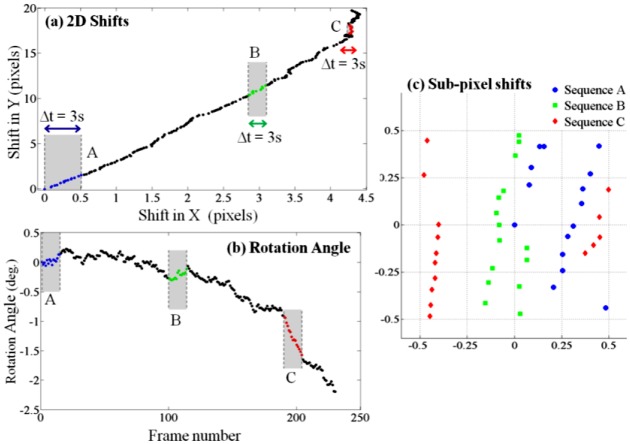
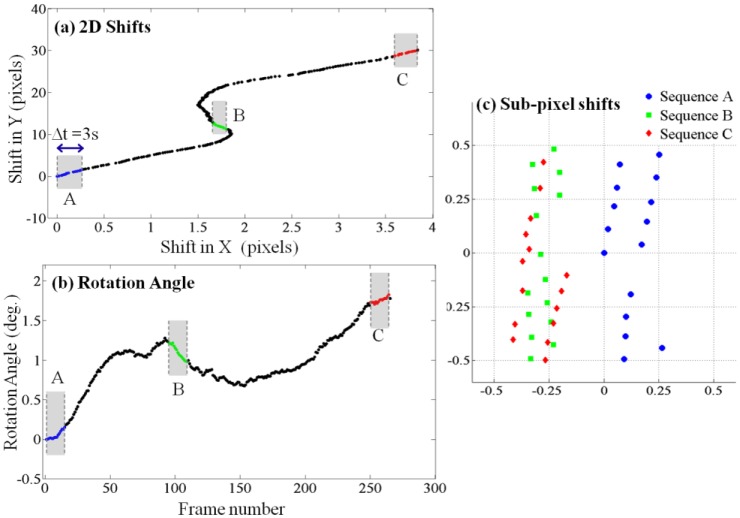
The first step towards generating a high-resolution hologram from multiple frames is the estimation of the shifts and rotations of object in different frames. As the shifts and rotations between two consecutive frames are small, we chose to use an iterative gradient method [28] for simultaneous estimation of the in-plane shift and in-plane rotation between all pairs of consecutive frames. Figure 2 shows the estimated in-plane shifts and in-plane rotation angle of all frames with respect to the first frame, and the sub-pixel shifts of different sets of 15 consecutive frames. Integer pixel shifts are not useful for the pixel super-resolution algorithm and are discarded. The microfluidic channel used has a relatively large cross section (80 µm X 1 mm), and it did not undergo surface treatment of any sort. We believe that the non-uniformity of the C. elegans flow along the channel is due to these reasons. Nonetheless, we show next that pixel super-resolution can still generate higher resolution holograms from multiple frames.
Fig. 2.
Electro-kinetic motion: As the object flows through the micro-channel due to electro-kinetic motion, lensfree in-line holograms are continuously captured by the CMOS sensor at a rate of ~5-6 frames/sec. Acquisition of ~15 consecutive frames is sufficient to generate a high-resolution HOM image, but for image comparison purposes, 230 frames were captured during ~45 seconds. (a) The two-dimensional lateral shifts of consecutive frames with respect to the first one. (b) In-plane rotation angles of consecutive frames with respect to the first one. (c) Sub-pixel shifts of 3 sequences (A, B and C), each composed of 15 consecutive frames are shown. These 3 sequences of lensfree raw holograms are used independently to generate 3 different HOM images. Integer pixel shifts are not useful for the super-resolution algorithm and are therefore digitally subtracted out.
To recover a high-resolution image of the object, not all of these shifted holograms are required, and in fact starting from an arbitrary initial point in time, only ~15 consecutive frames would be sufficient. To illustrate this, we have focused on 3 random sub-sequences of frames (Sequence A, B and C as highlighted in Figs. 2(a)-2(b), each of which contains 15 consecutive lensfree holograms of the moving sample acquired over ~3 seconds. To test a more challenging imaging condition, Sequence C was specifically chosen in a region where there is considerable rotation of the sample between the consecutive frames as quantified in Fig. 2(b).
The super-resolved hologram is computed from a sequence of lensfree raw holograms, such that given this high-resolution hologram, blurring it by the pixel sensitivity map and then downsampling it with different shifts recovers all the low-resolution measured raw holograms. We carried out this process by iteratively minimizing a cost function that is defined by the mean square error between the downsampled versions of the high-resolution hologram and their corresponding measured frames [28]. To regularize this optimization step and reduce artifacts, we also added a penalty to the cost function for high-frequency components of the super-resolved hologram. The cost function was minimized using a conjugate gradient method implemented in Matlab, which took ~2.5 seconds to converge on a 3.2 GHz PC, and 0.25 seconds using Graphics Processing Units (GPUs).
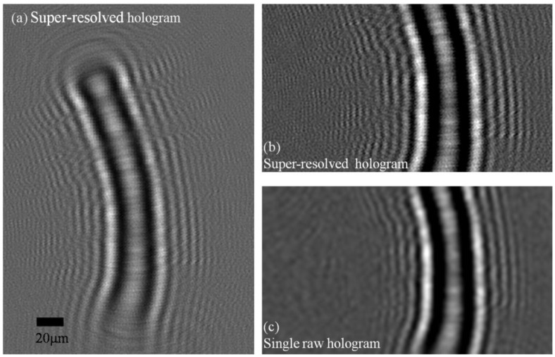
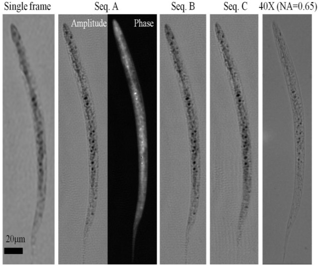
For each sub-sequences of 15 frames shown in Fig. 2 we have created a super-resolved hologram of the worm within the micro-fluidic channel. The super-resolved hologram from Sequence A is shown in Fig. 3 . Also shown is a single lensfree raw hologram of the same worm to better present the increased fringe visibility of the synthesized hologram. This super-resolved hologram is then processed using a custom-developed iterative twin-image elimination algorithm [23,24], to reconstruct a higher resolution image of the worm (both amplitude and phase) as shown in Fig. 4 . This reconstruction took 15 iterations, and was computed in 0.2 sec using a GPU. For comparison purposes, the reconstruction results of a lensfree raw hologram (corresponding to a single frame) is also shown in Fig. 4 together with a conventional transmission microscope image of the same sample acquired using a 40X objective lens (NA = 0.65). To further illustrate the performance of HOM, the same figure also shows the reconstruction results of the other 2 selected sub-sequences (Sequences B and C of Fig. 2), both of which mirror the reconstruction results of Sequence A. It is evident from these figures that a super-resolved hologram generated from holograms of a flowing object produces a finer resolution image compared to using a single frame from a stationary object. It is also worth noting that the results appear to be robust to the small in-plane rotation between frames in a given sequence of frames, and to the variation in shifts between different sequences.
Fig. 3.
(a) A super-resolved hologram of a C. elegans sample is shown. This high-resolution hologram is digitally computed using sequence A of Fig. 2 (15 consecutive lensfree raw holograms). (b) An enlarged section of (a), where sub-pixel holographic oscillation are observed. (c) An enlarged section of one of the raw holograms is shown. Contrast is digitally enhanced in (b) and (c) for better visualization of the differences between the raw and super-resolved holograms.
Fig. 4.
HOM images of a C. elegans sample. A single raw lensfree hologram gives a lower resolution image of the object after twin image elimination as shown in the far left image. When using 15 consecutive holographic frames of sequence A (Fig. 2) a super-resolved hologram is synthesized to create higher-resolution amplitude and phase images of the same worm. To demonstrate the robustness of this method, two additional sequences (B and C - see Fig. 2) were independently used to generate similar reconstructed images. The rightmost image of the worm is acquired using a conventional bright field microscope with a 40X objective lens (NA = 0.65), and is provided for comparison.
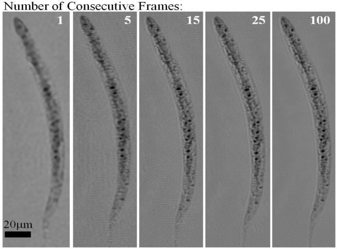
To further investigate the imaging behavior of HOM, in Fig. 5 we compare our reconstruction results for varying number of consecutive holographic frames. The super-resolution results presented in Fig. 4 were for 15 consecutive frames corresponding to an image acquisition time of ~3 sec. In Fig. 5, we compared the reconstruction results of 5, 15, 25 and 100 consecutive holographic frames, which indicate that after a sequence length of 15 consecutive frames, the image improvement becomes unnoticeable. The optimal number of frames and the optimal imaging duration in HOM depend on the speed of flow in the channel, the angle of flow as well as the frame rate of the sensor-chip. A faster frame rate along with an appropriately faster flow would further reduce the imaging time of each object within the micro-channel.
Fig. 5.
Electro-kinetic HOM images with different number of consecutive frames used as input to the pixel super-resolution algorithm. The images show progressive enhancement with increasing number of frames, however additional frames beyond 15 do not appear to offer further enhancement. ~3 seconds were required to capture 15 frames at 5fps, and a faster frame rate would allow significant reduction in image acquisition time.
These proof-of-concept experiments validated that regardless of the starting point, ~15 consecutive frames could synthesize a high-resolution HOM image. Furthermore, they also highlight another interesting property of HOM, i.e., the acquired sequence of lensfree raw holograms provides not only high-resolution images of the samples within a micro-fluidic channel but also can quantify the flow properties of the same objects, including dynamic speed, lateral shift as well as in-plane rotation, without affecting the image quality.
Next, we tested HOM with pressure driven flow, which is expected to be less uniform than electro-kinetic flow. The flow was driven by a slight imbalance of pressure between the two ends of the microfluidic channel, creating an object speed of ~2 µm/sec. As with the electro-kinetic flow case, we loaded the C. elegans samples into the channel and captured ~260 consecutive frames during the flow through the channel. We observed that indeed pressure flow caused more rotation of the worm and the flow was less uniform. We attribute that to the pressure flow and the absence of any surface treatment of the microfluidic channel, which leads to accumulation of small debris along the channel surface and in turn leads to surface roughness. The shifts and rotation of the different frames calculated with respect to the first frame are shown in Fig. 6 .
Fig. 6.
Pressure flow: By creating a pressure imbalance between the two ends of the micro-fluidic channel, the sample was forced to flow along the channel and frames were continuously captured. Again, only 15 consecutive frames were used to generate the HOM images, but image acquisition continued for ~45 seconds to provide image comparisons. (a) The two-dimensional lateral shifts of consecutive frames with respect to the first one. (b) In-plane rotation angles of consecutive frames with respect to the first one. (c) Sub-pixel shifts of 3 sequences (A, B and C), each composed of 15 consecutive frames are shown.
Similar to the electro-kinetic flow case, 15 consecutive frames were sufficient for synthesis of super-resolved holograms of the flowing objects. Once more, we chose 3 different random sub-sequences (A, B and C) from the pressure driven flow frames, composed of 15 frames (see Figs. 6(a)-6(b)) and processed these consecutive lensfree holograms to recover higher resolution images (both amplitude and phase) of the worm as shown in Fig. 7 . The images from the different sequences match each other and the conventional bright-field microscope image of the same sample. Despite the less uniform nature of the pressure driven flow compared to the electro-kinetic flow, HOM performs equally well in both cases and provides microscope images of comparable quality to conventional bright field microscope images.
Fig. 7.
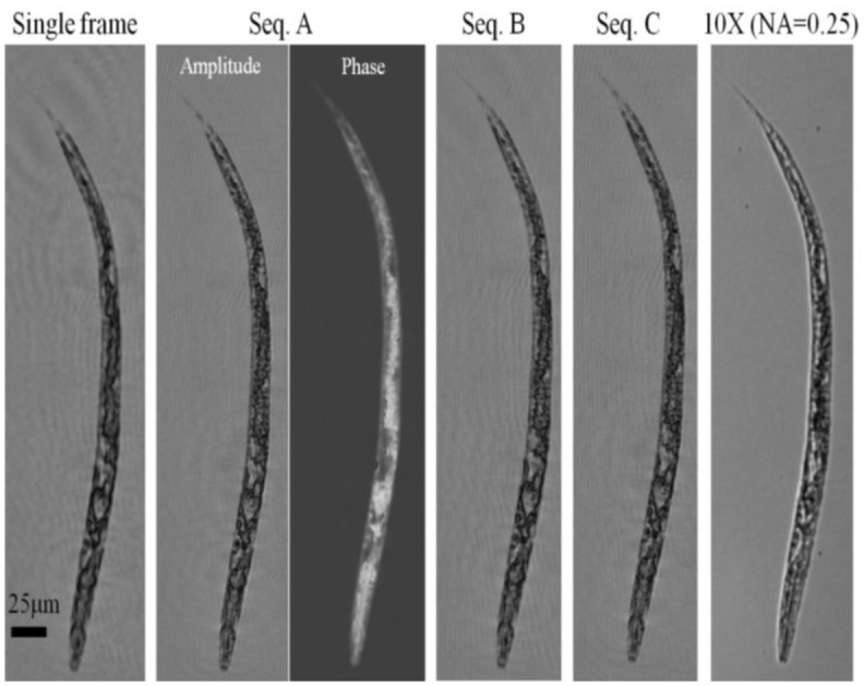
Pressure driven HOM images of a C. elegans sample. As with the electro-kinetic flow case (Fig. 4), we have used 3 different sequences (A, B and C) of 15 consecutive frames to generate 3 independent HOM images. The HOM images from all sequences are comparable. A 10X microscope objective lens image (NA = 0.25) is shown for comparison.
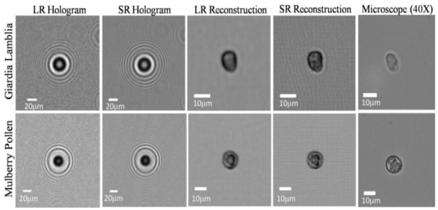
We have also successfully applied the HOM platform to image smaller sized micro-objects such as Giardia lamblia cysts and Mulberry pollen samples using the same micro-fluidic channels. In Fig. 8 we show holograms and HOM images of Giardia lambia cysts and of Mulberry pollen. The raw holograms of both objects exhibit visible aliasing as is apparent from the curvature of the outer fringes. Once 15 frames are incorporated into a single super-resolved hologram, aliasing is resolved, resulting in higher resolution images.
Fig. 8.
HOM imaging results are summarized for a Giardia lamblia cyst and a Mulberry pollen. The low-resolution (LR) hologram exhibit aliasing which is resolved in the super-resolved (SR) hologram. Note that because of the smaller dimensions of these flowing objects, it is not practically feasible to provide the exact microscope comparison images of the same samples, and therefore representative microscope images of the same species are provided. The flow velocity in both cases was 2-3 μm/s, and the flow was electro-kinetic.
4. Discussion
As far as spatial resolution is concerned, the presented HOM approach is fundamentally limited by the detection signal to noise ratio, as all other digital microscopy modalities are. If the signal to noise ratio of each pixel is further improved, a smaller effective pixel size can be achieved (e.g. < 400nm) and higher frequency fringes would be detectable. In our experiments, the CMOS chip was kept at room temperature and the main source of noise was the relative intensity noise as well as fixed-pattern noise of the sensor. With the next generation sensor-arrays, we expect further improvements in our imaging performance. To estimate the lateral spatial resolution of HOM we compare the images obtained from a single raw hologram to those obtained from a super-resolved hologram using 15 raw holograms. This is done by comparing the radial spectral power of both low- and high- resolution images after interpolation to a common grid with pixel size 2.2 µm/8 = 0.275 µm, plotted in Fig. 9 . An image obtained from processing a single raw hologram has been shown to have an effective NA of ~0.15-0.2 [23,24]. By inspecting the radial spectral power of the images reported in Fig. 4 and Fig. 7, we estimate that pixel super-resolution in HOM approximately doubles the bandwidth of the images; hence we estimate HOM images to have an effective NA of ~0.3-0.4.
Fig. 9.

The radial spectral power of HOM images and images reconstructed from single raw holograms. (a) The radial spectral power of images with electro-kinetic flow (Fig. 4). (b) The radial spectral power of images with pressure flow (Fig. 7). In both cases the image radial frequency bandwidth is approximately doubled, leading to a doubling of the effective numerical aperture of the image. We therefore conclude that HOM has an effective NA of ~0.3-0.4.
As for throughput, the presented experimental demonstrations of HOM were limited by the frame rate of the CMOS sensor (~5-6 fps for a full-frame) yielding ~2-3 sec imaging time for a field of view of ~24 mm2. This is by no means a fundamental limitation as one can increase the flow speed as well as the frame rate of the sensor (e.g., to >100 fps) by choosing a sub-region of the sensor active area (~24 mm2). For each lensfree raw hologram, the integration time at the sensor chip was < 50 ms (at a modest illumination power of < 10µW). A smaller field of view of the sensor-chip combined with a brighter source can therefore lead to an imaging time of < 0.5 sec for each sample. Furthermore, multiple objects can be imaged simultaneously in the time window required for the desired number of frames, since a wide and long channel may be used, and then can be quickly flushed to allow a new set of objects into the channel to be imaged.
To summarize, we have presented a holographic opto-fluidic microscopy platform which offers a simple and robust implementation of lensfree on-chip microscopy along with the possibility of integration within lab-on-a-chip devices. In this opto-fluidic imaging technique, we acquire a series of lensfree digital holograms of objects as they flow within a micro-fluidic channel. These lensfree in-line holograms are then digitally processed to synthesize a super-resolved hologram of the same object with an effective pixel size that is much smaller than the physical pixel size of the sensor-chip. An iterative phase-retrieval algorithm is used for the holographic twin-image elimination of this super-resolved hologram to create a high-resolution microscope image of the flowing object, in both amplitude and phase. This approach requires neither special fabrication steps nor careful alignment. It has also been demonstrated that this approach is tolerant to non-uniform in-plane object movement and in-plane rotation, and therefore does not require ideal uniform flow of the samples and may be used under different flow conditions.
Acknowledgments
A. Ozcan gratefully acknowledges the support of NSF CAREER Award, the Office of Naval Research (through Young Investigator Award 2009) and the NIH Director's New Innovator Award ( DP2OD006427 from the Office of the Director, NIH). The authors also acknowledge support of the Bill & Melinda Gates Foundation, Vodafone Americas Foundation, the National Science Foundation BISH Program (awards 0754880 and 0930501), the National Institutes of Health (NIH, under grant 1R21EB009222-01) and AFOSR (under project 08NE255). We also acknowledge Serhan Isikman of UCLA for his helpful discussions. Finally, we also acknowledge Askin Kocabas of Harvard University for his kind assistance with the samples.
References and Links
- 1.Y. Fainman, Optofluidics: Fundamentals, Devices, and Applications (McGraw-Hill, 2010). [Google Scholar]
- 2.Psaltis D., Quake S. R., Yang C., “Developing optofluidic technology through the fusion of microfluidics and optics,” Nature 442(7101), 381–386 (2006). 10.1038/nature05060 [DOI] [PubMed] [Google Scholar]
- 3.Monat C., Domachuk P., Eggleton B. J., “Integrated optofluidics: A new river of light,” Nat. Photonics 1(2), 106–114 (2007). 10.1038/nphoton.2006.96 [DOI] [Google Scholar]
- 4.Squires T., Quake S., “Microfluidics: Fluid physics at the nanoliter scale,” Rev. Mod. Phys. 77(3), 977–1026 (2005). 10.1103/RevModPhys.77.977 [DOI] [Google Scholar]
- 5.Whitesides G. M., “The origins and the future of microfluidics,” Nature 442(7101), 368–373 (2006). 10.1038/nature05058 [DOI] [PubMed] [Google Scholar]
- 6.R. Oosterbroek, Lab-on-a-Chip: Miniaturized Systems for (bio)chemical Analysis and Synthesis, 1st ed. (Elsevier, 2003). [Google Scholar]
- 7.Yager P., Edwards T., Fu E., Helton K., Nelson K., Tam M. R., Weigl B. H., “Microfluidic diagnostic technologies for global public health,” Nature 442(7101), 412–418 (2006). 10.1038/nature05064 [DOI] [PubMed] [Google Scholar]
- 8.Chin C. D., Linder V., Sia S. K., “Lab-on-a-chip devices for global health: past studies and future opportunities,” Lab Chip 7(1), 41–57 (2006). 10.1039/b611455e [DOI] [PubMed] [Google Scholar]
- 9.Dittrich P. S., Manz A., “Lab-on-a-chip: microfluidics in drug discovery,” Nat. Rev. Drug Discov. 5(3), 210–218 (2006). 10.1038/nrd1985 [DOI] [PubMed] [Google Scholar]
- 10.Haeberle S., Zengerle R., “Microfluidic platforms for lab-on-a-chip applications,” Lab Chip 7(9), 1094–1110 (2007). 10.1039/b706364b [DOI] [PubMed] [Google Scholar]
- 11.Craighead H., “Future lab-on-a-chip technologies for interrogating individual molecules,” Nature 442(7101), 387–393 (2006). 10.1038/nature05061 [DOI] [PubMed] [Google Scholar]
- 12.Weigl B. H., Bardell R. L., Cabrera C. R., “Lab-on-a-chip for drug development,” Adv. Drug Deliv. Rev. 55(3), 349–377 (2003). 10.1016/S0169-409X(02)00223-5 [DOI] [PubMed] [Google Scholar]
- 13.El-Ali J., Sorger P. K., Jensen K. F., “Cells on chips,” Nature 442(7101), 403–411 (2006). 10.1038/nature05063 [DOI] [PubMed] [Google Scholar]
- 14.Li Z., Zhang Z., Emery T., Scherer A., Psaltis D., “Single mode optofluidic distributed feedback dye laser,” Opt. Express 14(2), 696–701 (2006). 10.1364/OPEX.14.000696 [DOI] [PubMed] [Google Scholar]
- 15.Dong L., Agarwal A. K., Beebe D. J., Jiang H., “Adaptive liquid microlenses activated by stimuli-responsive hydrogels,” Nature 442(7102), 551–554 (2006). 10.1038/nature05024 [DOI] [PubMed] [Google Scholar]
- 16.Heng X., Erickson D., Baugh L. R., Yaqoob Z., Sternberg P. W., Psaltis D., Yang C., “Optofluidic microscopy--a method for implementing a high resolution optical microscope on a chip,” Lab Chip 6(10), 1274–1276 (2006). 10.1039/b604676b [DOI] [PubMed] [Google Scholar]
- 17.L. M. Lee, X. Cui, and C. Yang, “The application of on-chip optofluidic microscopy for imaging Giardia lamblia trophozoites and cysts,” Biomed Microdevices (2009). [DOI] [PMC free article] [PubMed] [Google Scholar]
- 18.Zheng G., Lee S. A., Yang S., Yang C., “Sub-pixel resolving optofluidic microscope for on-chip cell imaging,” Lab Chip 10(22), 3125–3129 (2010). 10.1039/c0lc00213e [DOI] [PubMed] [Google Scholar]
- 19.Bishara W., Su T. W., Coskun A. F., Ozcan A., “Lensfree on-chip microscopy over a wide field-of-view using pixel super-resolution,” Opt. Express 18(11), 11181–11191 (2010). 10.1364/OE.18.011181 [DOI] [PMC free article] [PubMed] [Google Scholar]
- 20.Haddad W. S., Cullen D., Solem J. C., Longworth J. W., McPherson A., Boyer K., Rhodes C. K., “Fourier-transform holographic microscope,” Appl. Opt. 31(24), 4973–4978 (1992). 10.1364/AO.31.004973 [DOI] [PubMed] [Google Scholar]
- 21.Xu W., Jericho M. H., Meinertzhagen I. A., Kreuzer H. J., “Digital in-line holography for biological applications,” Proc. Natl. Acad. Sci. U.S.A. 98(20), 11301–11305 (2001). 10.1073/pnas.191361398 [DOI] [PMC free article] [PubMed] [Google Scholar]
- 22.Garcia-Sucerquia J., Xu W., Jericho M. H., Kreuzer H. J., “Immersion digital in-line holographic microscopy,” Opt. Lett. 31(9), 1211–1213 (2006). 10.1364/OL.31.001211 [DOI] [PubMed] [Google Scholar]
- 23.Oh C., Isikman S. O., Khademhosseinieh B., Ozcan A., “On-chip differential interference contrast microscopy using lensless digital holography,” Opt. Express 18(5), 4717–4726 (2010). 10.1364/OE.18.004717 [DOI] [PMC free article] [PubMed] [Google Scholar]
- 24.Mudanyali O., Tseng D., Oh C., Isikman S. O., Sencan I., Bishara W., Oztoprak C., Seo S., Khademhosseini B., Ozcan A., “Compact, light-weight and cost-effective microscope based on lensless incoherent holography for telemedicine applications,” Lab Chip 10(11), 1417–1428 (2010). 10.1039/c000453g [DOI] [PMC free article] [PubMed] [Google Scholar]
- 25.Park S. C., Park M. K., Kang M. G., “Super-resolution image reconstruction: a technical overview,” IEEE Signal Process. Mag. 20(3), 21–36 (2003). 10.1109/MSP.2003.1203207 [DOI] [Google Scholar]
- 26.Hardie R. C., Barnard K. J., Armstrong E. E., “Joint MAP registration and high-resolution image estimation using a sequence of undersampled images,” IEEE Trans. Image Process. 6(12), 1621–1633 (1997). 10.1109/83.650116 [DOI] [PubMed] [Google Scholar]
- 27.Woods N. A., Galatsanos N. P., Katsaggelos A. K., “Stochastic methods for joint registration, restoration, and interpolation of multiple undersampled images,” IEEE Trans. Image Process. 15(1), 201–213 (2006). 10.1109/TIP.2005.860355 [DOI] [PubMed] [Google Scholar]
- 28.Hardie R. C., Bognar J. G, Armstrong E. E, Watson E. A, “High-resolution image reconstruction from a sequence of rotated and translated frames and its application to an infrared imaging system,” Opt. Eng. 37, 247 (1998). 10.1117/1.601623 [DOI] [Google Scholar]
- 29.Z. Zalevsky, and D. Mendlovic, Optical Superresolution (Springer Verlag, 2004). [Google Scholar]
- 30.Gustafsson M. G. L., “Nonlinear structured-illumination microscopy: wide-field fluorescence imaging with theoretically unlimited resolution,” Proc. Natl. Acad. Sci. U.S.A. 102(37), 13081–13086 (2005). 10.1073/pnas.0406877102 [DOI] [PMC free article] [PubMed] [Google Scholar]
- 31.Willig K. I., Rizzoli S. O., Westphal V., Jahn R., Hell S. W., “STED microscopy reveals that synaptotagmin remains clustered after synaptic vesicle exocytosis,” Nature 440(7086), 935–939 (2006). 10.1038/nature04592 [DOI] [PubMed] [Google Scholar]
- 32.Betzig E., Patterson G. H., Sougrat R., Lindwasser O. W., Olenych S., Bonifacino J. S., Davidson M. W., Lippincott-Schwartz J., Hess H. F., “Imaging intracellular fluorescent proteins at nanometer resolution,” Science 313(5793), 1642–1645 (2006). 10.1126/science.1127344 [DOI] [PubMed] [Google Scholar]
- 33.Rust M. J., Bates M., Zhuang X., “Sub-diffraction-limit imaging by stochastic optical reconstruction microscopy (STORM),” Nat. Methods 3(10), 793–796 (2006). 10.1038/nmeth929 [DOI] [PMC free article] [PubMed] [Google Scholar]


