Abstract
We have developed a dual-modality biomedical imaging probe utilizing intravascular ultrasound (IVUS) and optical coherence tomography (OCT). It consists of an OCT probe, a miniature ultrasonic transducer and a fixed mirror. The mirror was mounted at the head of the hybrid probe 45° relative to the light and the ultrasound beams to change their propagation directions. The probe was designed to be able to cover a larger area in blood vessel by IVUS and then visualize a specific point at a much finer image resolution using OCT. To demonstrate both its feasibility and potential clinical applications, we used this ultrasound-guide OCT probe to image a rabbit aorta in vitro. The results offer convincing evidence that the complementary natures of these two modalities may yield beneficial results that could not have otherwise been obtained.
I. Introduction
A therosclerosis, one of the major causes of mortality in developed countries, is basically the hardening of the arterial vessel wall caused by athermanous plaques [1]. To assess the morphology and severity of atherosclerotic lesions, biomedical imaging techniques such as angiography, CT angiography (CTA), and contrast-enhanced magnetic resonance angiography (CE-MRA) have been developed [2], [3]. However, angiography and CTA are X-ray-based invasive techniques and require the injection of a contrast agent into the blood vessel. These contrast agents may lead to serious allergic reactions and can be harmful to the patients with kidney disease [4]. CE-MRA, in contrast, is safer because it has no ionizing radiation and its contrast agents tend to be less toxic. However, the major drawbacks of CE-MRA are its relatively high cost and long processing time [5].
Intravascular ultrasound (IVUS), a catheter-based technique, has been increasingly used for the clinical detection and diagnosis of atherosclerosis to overcome the drawbacks of these imaging modalities [6]. IVUS has several advantages, such as its low cost and lack of radiation and contrast agent. IVUS allows doctors to obtain detailed, accurate images of diseased vessels from inside the artery and simultaneously evaluate their size [7]. However, one of the drawbacks of IVUS is its limited image resolution, which depends on the wavelength of the sound beam. This is a major weakness when diagnosing the plaques, compared with the other imaging modalities [8]. Higher resolution IVUS images can be achieved using a high-frequency ultrasound transducer, but this comes at the cost of a limited penetration depth [9].
Unlike IVUS, optical coherence tomography (OCT) is a newly developed optical technology providing real-time, noninvasive, and high-resolution 3-D-images with micrometer resolution, which can be 1 to 2 orders of magnitude smaller than that of IVUS [10]. Characterized by excellent surface image resolution, intravascular OCT has been used recently to visualize the arteries to detect vulnerable lipid-rich plaques [11], [12]. However there are two limitations of OCT when used for intravascular imaging applications. First, OCT is restricted to imaging 1 to 2 mm below the surface in turbid biological tissue, which makes it difficult to give entire cross-sectional information regarding artery anatomy and provide quantitative arterial thickness measurements. Second, OCT requires displacing arterial blood to minimize scattering by infusing a saline solution. To alleviate the effects of the saline solution on blood circulation, only a minimum amount of saline flushing will be used for OCT once the area of interest has been found by IVUS.
Therefore, a complementary integrated IVUS-OCT probe may be suitable for cutting-edge intravascular imaging applications. The superior resolution of OCT enables accurate characterization of athermanous plaques, and IVUS can provide an overall image of the vessel wall [11]. In fact, research has demonstrated a high agreement between the two complementary techniques on the detection of fibrous, fibrocalcific, and neurotic core regions [8], [13]. The feasibility of the combined use of IVUS and OCT data (images acquired separately) for detecting thin-cap fibroatheroma (TCFA) with 56 patients has been studied by Sawada et al. [8]. The results clearly show that neither modality alone is sufficient for detecting TCFA. Therefore, the combined use of OCT and IVUS provides an excellent approach for evaluating TCFA.
To respond to these needs, we have reported a preliminary result using an integrated IVUS-OCT probe [14]. This probe was developed with the hope that by utilizing both modalities, the shortcomings of both may be minimized. also several researchers have very recently presented the concept of an OCT/IVUS dual-modality catheter [15], [16]. However our work is the first to report of implementation of a dual-modality probe. In this paper, we present an in vitro image study of the ultrasound-guided OCT dual-modality probe to show its tremendous potential for use in intravascular imaging applications.
II. Materials And Methods
For an IVUS ultrasound transducer, a piezoelectric material with a high kt (the thickness mode electromechanical coupling coefficient) is always preferable, such as Pb(Mg1/3Nb2/3)O3-PbTio3 (PMN-PT). Therefore, in this study, a 67%PMN-33%PT (kt = 0.58, HC Materials Corp., Urbana, IL) single crystal was selected and then lapped down to 55 μm and electroplated with 1000/500 Å of gold/chrome. A matching layer (Z = 7.3 Mrayl) made of Insulcast 501 and Insulcure 9 (American Safety Technologies, Roseland, NJ) and 2- to 3-μm silver particles (Sigma-Aldrich Inc., St. Louis, MO) was centrifuged, cured, and then lapped down to approximately λ/4 thickness over the surface of the PMN-PT plate. Conductive epoxy (E-SOLDER 3022, Von Roll Isola Inc., New Haven, CT) was applied as the backing material, using the same centrifugal casting and curing procedure as the matching layer. more detail about the design and fabrication of a high-frequency ultrasound transducer has been reported in our previous work [17]. This transducer’s center frequency was designed to be 35 MHz, which was a compromise between the resolution and penetration depth required for our application. The square aperture of the PMN-PT was 0.4 × 0.4 mm to match the 50 Ω electrical impedance of commercial systems. The outside diameter of this transducer was restricted to 1.5 mm to fit within the size limitation of the blood vessels of interest.
The OCT probe was assembled next to the aforementioned ultrasound transducer. This endoscopic OCT probe incorporated a 1310-nm single mode fiber was cut to 8 degrees and glued to a gradient-index (GRIN) lens. The axial and lateral resolutions of the OCT probe are 8 and 20 μm, respectively [16]. The OCT and IVUS probes were mounted inside a 2.8-mm-diameter stainless steel tube and then filled with epoxy (EPO-TEK 301, Epoxy Technology Billerica, MA). After combination, a 2-mm-diameter aluminum coated prism with a 45° angle (Edmund optics, Barrington, NJ) was mounted at the end of probe to allow for the required simultaneous radial scanning. The distance from this mirror to transducer surface is equal to one-half of the natural focus length of the transducer. The stainless steel tube was then enclosed by an optically transparent polystyrene tube (2.82 mm diameter) to prevent contamination from the environment, such as blood. A cross-sectional drawing of the finished probe is shown in Fig. 1.
Fig. 1.
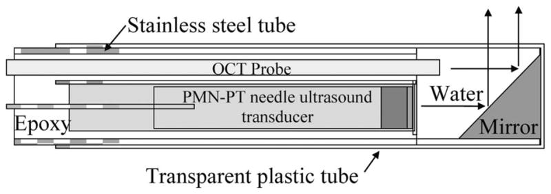
Schematic diagram of the hybrid probe.
III. Probe Evaluation
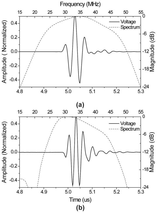
A commercial transducer modeling software Piezo-CAD (Sonic Concepts, Woodinville, WA) was used to simulate the performance of the ultrasound transducer and a pulse-echo test was performed using the Panametrics 5900PR pulser/receiver (Olympus NDT Inc., Waltham, MA) to evaluate this transducer. Fig. 2 shows the modeled and measured pulse-echo signals and spectra. In Fig. 2(a), the designed center frequency was 35 MHz, and the −6-dB fractional bandwidth was 65%. The measured center frequency of the fabricated transducer was 34 MHz, and −6-dB fractional bandwidth was 53% [Fig. 2(b)].
Fig. 2.
(a) Modeled and (b) measured pulse-echo waveform (solid line) and FFT spectrum (dashed line) for the PMN-PT ultrasound transducer.
A phantom consisting of five 20-μm-diameter tungsten wires (California Fine Wire Co., Grover Beach, CA) was then imaged to assess the axial and lateral resolutions of the IVUS transducer. The generated image was displayed using a logarithmic representation of pixel intensity with a 50 dB dynamic range (Fig. 3). It can be seen that all five wires could be resolved, but the image generated using the mirror shows a significant drop in SNR. The −6-dB axial and lateral resolutions for the PMN-PT transducer were calculated by looking at the line located at a depth of 4 mm (axial direction). The measured −6-dB resolutions at this depth were approximately 65 μm in the axial direction and 435 μm in the lateral. For a square unfocused transducer, the axial and the lateral resolutions can be estimated using the Field II simulation program [18]. Assuming the working distance of this transducer was 4 mm, then the modeled axial and lateral resolutions were 55 μm and 440 μm, respectively.
Fig. 3.
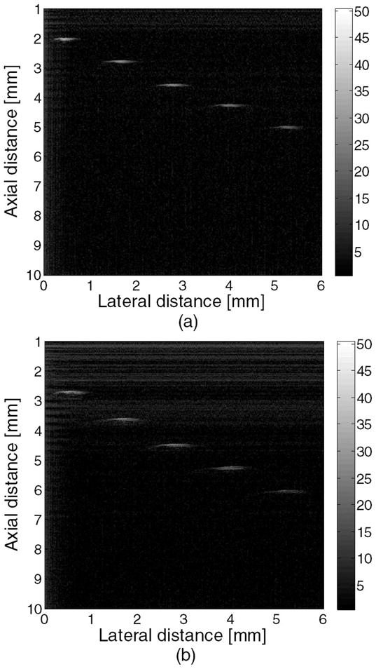
Wire phantom images acquired with this PMN-PT ultrasound transducer: (a) without a mirror and (b) with a mirror.
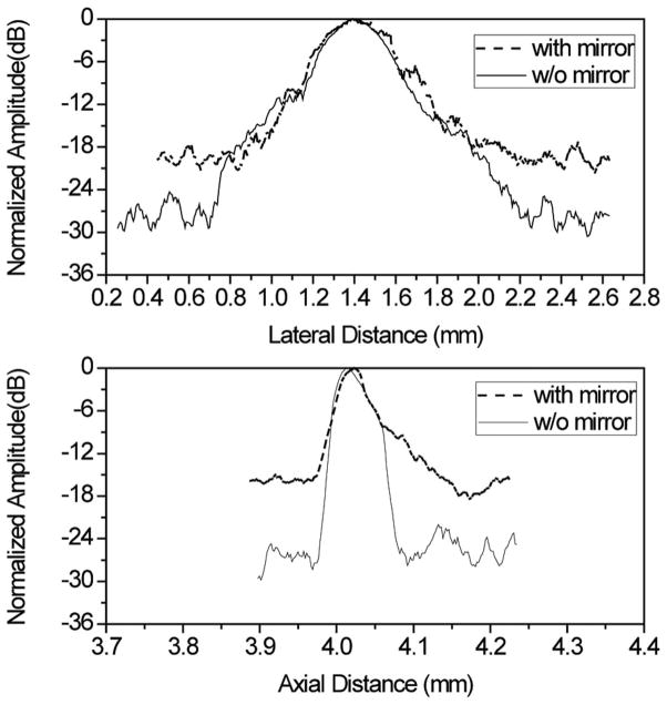
Fig. 4 provides the axial and lateral line spread function to show the effect of the mirror on the ultrasonic transducer’s image resolution and SNR. It has been observed that there is no major difference in the axial and lateral line spread functions at equal or less than −6 dB with reference to the peak. However, the SNR of the image acquired using a transducer with a mirror was roughly 10 dB lower than the ultrasound transducer without a mirror. This signal loss was caused by te absorption and/or imperfect mirror refection and may be compensated for in the future using several methods, such as increasing excitation energy to the transducer, or using low-noise amplifiers or filters.
Fig. 4.
Lateral and axial line spread functions generated with the PMN-PT ultrasound transducer (and with or without a mirror).
Next, the resulting hybrid probe was rotated mechanically to obtain in vitro intravascular images. again the Panametrics 5900PR pulser/receiver was used to excite the ultrasound transducer and receive the echoes. The echoes were then digitized by Gage A/D card (CS12400, Gage Applied Technologies Inc., Montreal, Quebec, Canada). Each A-mode echo signal was recorded with 14 dB gain for every two degrees in one rotation (180 lines in total). A MATLAB (The MathWorks, Natick, MA) program was then used to convert the radial A-mode data to a rectangular B-mode ultrasound image.
For the OCT system, the output light from a swept light source (Santec Corporation, Komaki, Aichi, Japan) at 1310 nm with a FWHM bandwidth of 100 nm and output power of 5 mW was split into reference and sample arms using a 1 × 2 coupler. The light source was operated at a sweeping rate of 20 kHz. Eighty percent of the incident power was coupled into the sample arm; the rest was fed into the reference arm. A data acquisition board (PXI5122, National Instruments, Austin, TX) was used to digitize the return signals. The sampling rate was set to be 33 MHz for the OCT system. a schematic diagram of this hybrid imaging system is given in Fig. 5.
Fig. 5.
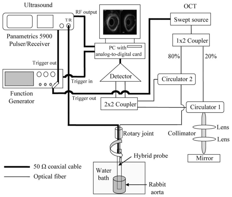
schematic diagram of the in vitro rabbit aorta imaging system.
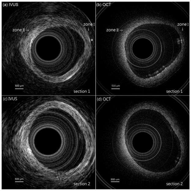
Fig. 6(a) shows the IVUS image of a rabbit aorta acquired using the hybrid probe. It can be seen that the ultrasound has penetrated the blood vessel, forming a clear cross-sectional image. The average thickness of this aorta is approximately 1.0 mm. An OCT image of the same aorta is shown in Fig. 6(b). The concentric circular structures seen in the middle are the inner and outer surfaces of the plastic protective tube. These artifacts were caused by the difference of refraction coefficients of the plastic and the water. In addition, the overlapping of the vessel and the tube was caused by the probe touching the vessel’s surface when it was rotated. Obviously, Fig. 6(b) reveals more details of the surface structure of the vessel and the inner profile of the vessel was more precisely obtained than in Fig. 6(a). Nevertheless, Fig. 6(b) does not show a cross-sectional structure of this aorta, but Fig. 6(a) does (see Zone I). The area marked with an asterisk in Fig. 6(a) shows that IVUS can even image the blood capillary, located on the other side of this aorta. It can be seen that OCT is not able to visualize a deeper target, such as early-stage atherosclerosis, hiding under the vessel surface because of OCT’s limited penetration depth. For example, in Fig. 6(a) (see Zone II), a deeper vessel structure was visible with IVUS, but not by OCT in the corresponding position in Fig. 6(b). However, OCT can better delineate subtle changes in the vessel surface, which will be helpful for characterizing plaques.
Fig. 6.
Images of two sections of a rabbit aorta: (a) shows the IVUS image of section 1, (b) shows the OCT image of section 1, (c) shows the IVUS image of section 2, and (d) shows the OCT image of section 2.
To demonstrate the system’s repeatability, the IVUS and OCT images of another section of the same rabbit aorta are shown in Figs. 6(c) and 6(d), respectively. Clearly, IVUS is good at covering a large area without losing its ability to pinpoint a specific target, whereas OCT is useful for imaging structures closer to the surface of that target at a much finer resolution. Thus, these results demonstrate that images gathered via IVUS and OCT can be complementary.
IV. Discussion And Conclusions
A dual-modality biomedical imaging probe using IVUS and OCT technologies has been developed and in vitro images of a rabbit aorta were acquired. These images have successfully demonstrated the feasibility and potential of this dual-modality probe. We believe that the ultrasound-guided OCT is a promising approach for detecting plaques. However, there are some drawbacks to this probe configuration. First, the small difference in the positioning of the IVUS and the OCT probes creates slightly different imaging areas. This issue can be solved using a ring ultrasound transducer and placing the OCT optic fiber inside it. another problem is that a significant portion of the ultrasound signal is lost because of absorption or imperfect refection when using a mirror. To minimize this loss, a polished reflector made of high acoustic impedance materials, such as stainless steel or tungsten could be used. Finally, the size of the probe can be an issue. Although a 2.82-mm diameter probe is suitable for an in vitro experiment, a smaller probe is required to do an in vivo intravascular imaging experiment in the future. Our research on how to minimize the probe size is ongoing.
Acknowledgments
This work is based on research supported by NIH (P41-EB2182, CA-91717, EB-1090) and the U.S. Air Force Office of Scientific Research, Medical Free-Electron Laser Program FA9550-08-1-0384.
We thank Mr. J. Williams and Dr. D. Wu for their aid in fabricating the PMT-PT transducer. We also thank HC Materials Corp., Urbana, IL, for providing the PMN-PT single crystal.
Contributor Information
Hao-Chung Yang, Email: yangh@usc.edu, NIH Transducer Resource Center and Department of Biomedical Engineering, University of Southern California, Los Angeles, CA.
Jiechen Yin, Beckman Laser Institute and Department of Biomedical Engineering, University of California, Irvine, Irvine, CA.
Changhong Hu, NIH Transducer Resource Center and Department of Biomedical Engineering, University of Southern California, Los Angeles, CA.
Jonathan Cannata, NIH Transducer Resource Center and Department of Biomedical Engineering, University of Southern California, Los Angeles, CA.
Qifa Zhou, NIH Transducer Resource Center and Department of Biomedical Engineering, University of Southern California, Los Angeles, CA.
Jun Zhang, Beckman Laser Institute and Department of Biomedical Engineering, University of California, Irvine, Irvine, CA.
Zhongping Chen, Beckman Laser Institute and Department of Biomedical Engineering, University of California, Irvine, Irvine, CA.
K. Kirk Shung, NIH Transducer Resource Center and Department of Biomedical Engineering, University of Southern California, Los Angeles, CA.
References
- 1.Libby P. Inflammation in atherosclerosis. Nature. 2002;420(6917):868–874. doi: 10.1038/nature01323. [DOI] [PubMed] [Google Scholar]
- 2.Schwartz RB, Jones KM, Chernoff DM, Mukherji SK, Khorasani R, Tice HM, Kikinis R, Hooton SM, Stieg PE, Polak JF. Common carotid artery bifurcation: Evaluation with spiral CT. Radiology. 1992;185(2):513–519. doi: 10.1148/radiology.185.2.1410365. [DOI] [PubMed] [Google Scholar]
- 3.Alvarez-Linera J, Benito-Leon J, Escribano J, Campollo J, Gesto R. Prospective evaluation of carotid artery stenosis: Elliptic centric contrast-enhanced MR angiography and spiral CT angiography compared with digital subtraction angiography. AJNR Am J Neuroradiol. 2003;24(9):1012–1019. [PMC free article] [PubMed] [Google Scholar]
- 4.Mettler FA, Jr, Wiest PW, Locken JA, Kelsey CA. CT scanning: Patterns of use and dose. J Radiol Prot. 2000;20(4):353–359. doi: 10.1088/0952-4746/20/4/301. [DOI] [PubMed] [Google Scholar]
- 5.Scarabino T, Carriero A, Magarelli N, Florio F, Giannatempo GM, Bonomo L, Salvolini U. MR angiography in carotid stenosis: A comparison of three techniques. Eur J Radiol. 1998;28(2):117–125. doi: 10.1016/s0720-048x(97)00121-6. [DOI] [PubMed] [Google Scholar]
- 6.Potkin BN, Bartorelli AL, Gessert JM, Neville RF, Almagor Y, Roberts WC, Leon MB. Coronary artery imaging with intravascular high-frequency ultrasound. Circulation. 1990;81(5):1575–1585. doi: 10.1161/01.cir.81.5.1575. [DOI] [PubMed] [Google Scholar]
- 7.van deb Poll SWE, de Korte CL, van der Steen AFW, Puppels GJ, van der Laarse A. Coronary atherosclerotic plaque characterization using IVUS elastography and Raman spectroscopy. Proc 2000 IEEE Int Ultrasonics Symp. 2000:1775–1778. [Google Scholar]
- 8.Sawada T, Shite J, Garcia-Garcia HM, Shinke T, Watanabe S, Otake H, Matsumoto D, Tanino Y, Ogasawara D, Kawamori H, Kato H, Miyoshi N, Yokoyama M, Serruys PW, Hirata KI. Feasibility of combined use of intravascular ultrasound radiofrequency data analysis and optical coherence tomography for detecting thin-cap fibroatheroma. Eur Heart J. 2008;29(9):1136–1146. doi: 10.1093/eurheartj/ehn132. [DOI] [PubMed] [Google Scholar]
- 9.Lockwood GR, Ryan LK, Foster FS. A 45 to 55 MHz needle-based ultrasound system for invasive imaging. Ultrason Imaging. 1993;15(1):1–13. doi: 10.1177/016173469301500101. [DOI] [PubMed] [Google Scholar]
- 10.Huang D, Swanson EA, Lin CP, Schuman JS, Stinson WG, Chang W, Hee MR, Flotte T, Gregory K, Puliafto CA. Optical coherence tomography. Science. 1991;254(5035):1178–1181. doi: 10.1126/science.1957169. [DOI] [PMC free article] [PubMed] [Google Scholar]
- 11.Tearney GJ, Jang IK, Bouma BE. Optical coherence tomography for imaging the vulnerable plaque. J Biomed Opt. 2006;11(2):art. no. 021002. doi: 10.1117/1.2192697. [DOI] [PMC free article] [PubMed] [Google Scholar]
- 12.Fujimoto JG, Drexler W. Optical Coherence Tomography, Technology and Applications. 1. New York, NY: Springer; 2008. [Google Scholar]
- 13.Kawasaki M, Bouma BE, Bressner J, Houser SL, Nadkarni SK, Macneill BD, Jang IK, Fujiwara H, Tearney GJ. Diagnostic accuracy of optical coherence tomography and integrated backscatter intravascular ultrasound images for tissue characterization of human coronary plaques. J Am Coll Cardiol. 2006;48(1):81–88. doi: 10.1016/j.jacc.2006.02.062. [DOI] [PubMed] [Google Scholar]
- 14.Yang HC, Yin JC, Hu CH, Zhou QF, Cannata JM, Chen ZP, Shung KK. Novel biomedical imaging that combines intravascular ultrasound (IVUS) and optical coherence tomography (OCT) Proc 2008 IEEE Int Ultrasonics Symp. 2008:1769–1772. [Google Scholar]
- 15.Li BH, Leung AS, Munding CE, Thind AS, Munce NR, Lee H, Strauss BH, Foster S, Courtney BK. Hybrid ultrasound and optical imaging catheter for vascular disease characterization. Circulation. 2009;120(18):s948. [Google Scholar]
- 16.Yin J, Yang HC, Li X, Zhang J, Zhou Q, Hu C, Shung KK, Chen Z. Integrated intravascular-optical coherence tomography ultrasound imaging system. J Biomed Opt. 2010;15(1):art. no. 010512. doi: 10.1117/1.3308642. [DOI] [PMC free article] [PubMed] [Google Scholar]
- 17.Cannata JM, Ritter TA, Chen WH, Silverman RH, Shung KK. Design of efficient, broadband single-element (20–80 MHz) ultrasonic transducers for medical imaging applications. IEEE Trans Ultrason Ferroelectr Freq Control. 2003;50(11):1548–1557. doi: 10.1109/tuffc.2003.1251138. [DOI] [PubMed] [Google Scholar]
- 18.Jensen JA. Field: A program for simulating ultrasound systems. Med Biol Eng Comput. 1996;34:351–353. [Google Scholar]


