

Abstract
Due to their ability to serve as fluorophores and drug delivery vehicles, quantum dots are a powerful tool for theranostics-based clinical applications. In this study, microneedle devices for transdermal drug delivery were fabricated by means of two-photon polymerization of an acrylate-based polymer. We examined proliferation of cells on this polymer using neonatal human epidermal keratinocytes and human dermal fibroblasts. The microneedle device was used to inject quantum dots into porcine skin; imaging of the quantum dots was performed using multiphoton microscopy.
Keywords: microneedle, quantum dot, transdermal drug delivery, theranostics
Introduction
Theranostics, the combination of therapeutic and diagnostic technologies into a single platform, is a rapidly developing technology for treating a variety of medical conditions. For example, theranostics technologies may provide disease imaging and chemotherapy delivery for treatment of cancer, a group of conditions in which cells exhibit uncontrolled growth and invasion.1-5 Other applications of theranostics that are being investigated include use in diabetes, ocular disease, obesity, cardiovascular diseases, and infectious diseases.1,3,6
Quantum dots (QD) are 2-10 nm diameter fluorescent semiconductor nanostructured materials that are being considered for use in several theranostics applications. Due to the fact that the exciton Bohr radius (average electron-hole distance) is larger than the nanoparticle radius, these materials undergo quantum confinement. As a result, quantum dots demonstrate characteristic excitation states as well as larger bandgap values than bulk material. In addition, emission wavelength in these materials is size dependent; bandgap values for quantum dots increase as the nanoparticle radius decreases.7-10 Core-shell quantum dots are composed of a core material with a smaller bandgap than the surrounding shell material; zinc sulfide shells surrounding cadmium telluride cores, zinc sulfide shells surrounding cadmium selenide cores, and cadmium sulfide shells surrounding cadmium selenide cores are some examples of this type of quantum dots.7,11-13
Quantum dots exhibit unique photoluminescence behavior; some advantages of quantum dots over conventional fluorophores include greater resistance to light-dependent oxidation (photobleaching) and higher brightness, which is attributed to high quantum yield values and large molar extinction coefficient values.14 Passive mechanisms (e.g., preferential retention of quantum dots within tumor cells) may be utilized. Quantum dots may also be conjugated with peptides, antibodies, aptamers, pharmacologic agents, and other tumor-specific molecules that allow for specific tumor-cell interactions.15-20 For example, Derfus et al. conjugated tumor-homing peptides and small interfering RNA molecules to PEGlyated quantum dots. They demonstrated that the F3 tumor-homing peptide enabled tumor cell internalization.16 When F3 tumor-homing peptide/small interfering RNA-quantum dots were delivered to enhanced green fluorescent protein-transfected HeLa cells, knockdown of the enhanced green fluorescent protein signal was observed. Bagalkot et al. demonstrated processing of conjugates containing A10 aptamer (an RNA molecule that recognizes the extracellular domain of prostate-specific membrane antigen), doxorubicin (an anthracycline antineoplastic agent), and fluorescent quantum dots; in vitro studies demonstrated that these mutifunctional nanoparticles may be used for simultaneous targeted imaging, therapy, and sensing of prostate cancer cells.19 Tada et al. conjugated trastuzumab to quantum dots coated with polyethylene glycol amine; these structures were subsequently labeled with monoclonal anti HER2 antibody. The antibody-conjugated therapeutic nanoparticles were successfully demonstrated using a dorsal skinfold chamber in a murine model.15 Cai et al. conjugated a thiolated arginine-glycine-aspartic acid (RGD) peptide with polyethylene glycol-coated quantum dots; these structures were successfully utilized for in vivo tumor imaging in a murine model.20
It should be noted that quantum dots and other nanoscale pharmacologic agents cannot be administered in enteral form since they may be sequestered within the intestine, kidneys, liver, or lungs prior to entering systemic circulation.21-22 Intravenous delivery is the most common mechanism for quantum dot administration at this time because it enables instantaneous delivery of the quantum dots into the bloodstream. However, use of hypodermic needles is associated with several shortcomings, including injection site trauma, patient pain, and difficulty in providing sustained administration over an extended period of time. One option for quantum dot delivery involves the use of microneedles, which are needle-, lancet-, or thorn-shaped structures in which one dimension is less than 500 μm. These devices penetrate the stratum corneum layer of the epidermis; this 15 μm layer contains keratinized dead cells and serves as a barrier against transdermal movement of pharmacologic agents through the skin. Quantum dots may subsequently enter dermal blood vessels by passing through the lower part of the epidermis. Hollow microneedles enable pressure-driven or diffusion-driven delivery of quantum dots through the skin to be modulated over an extended period of time. In addition, microneedles may be used both for delivery of quantum dots as well as for withdrawal of blood and/or interstitial fluid. Microneedle devices commonly contain several microneedles; use of microneedle arrays is associated with injection at higher rates as well as injection over wider areas than use of solitary microneedles.23 Furthermore, redundant microneedles within the microneedle arrays may be utilized if some of the microneedles within the array are obstructed or damaged during use. Use of microneedles is associated with minimal tissue compression, nerve ending interaction, pain sensation, injection site trauma, and injection site inflammation.24-27
Recent studies have demonstrated delivery of nanomaterials by means of microneedles. For example, Coulman et al. used microneedles prepared by means of wet-etch techniques for delivery of fluorescent nanospheres across human epidermal membranes.28 McAllister et al. demonstrated that pores in the stratum corneum layer of human cadaver abdomen or back skin created by a solid microneedle array enabled transport of polystyrene latex nanoparticles29 Bal et al. recently utilized laser scanning microscopy to visualize movement of sodium fluorescein dye thorugh conduits in human skin, which were created by 300 μm long DermaStamp® microneedles.30 They proposed that laser scanning microscopy may be used to observe the dimensions of microneedle-fabricated conduits in viable human skin over time.
Microneedles with various geometries as well as microneedle arrays may be fabricated using a laser-based rapid prototyping process known as two photon polymerization.31-37 Two-photon polymerization involves temporal and spatial overlap of photons, which enables highly localized polymerization of a photosensitive resin. Nearly simultaneous absorption of two photons creates a so-called virtual state; this electronic excitation is analogous to excitation by a single photon with a higher energy. A diagram of the two-photon polymerization process is provided in Figure 1a. The minimum feature size obtained using two-photon polymerization is can be altered by changing the optics (e.g., the objective used to focus the laser beam). Two photon polymerization provides several advantages over conventional microelectronics-based techniques for fabrication of microneedles and other small-scale medical devices. The photosensitive materials used in two photon polymerization are widely available and are obtained at low cost. In contrast with cleanroom-based microfabrication techniques, photon polymerization can be performed in conventional environments. As opposed to conventional multiple-step microfabrication methods, two photon polymerization can create microneedles and other complex small-scale structures in a single-step process. Two photon polymerization has been used to fabricate a variety of small-scale medical devices, including scaffolds for regenerative medicine, ossicular replacement prostheses, and microneedles.31-38 For example, Doraiswamy et al. showed that organically-modified ceramic (Ormocer®) microneedles did not exhibit fracture during compression load testing with porcine skin.31 Ovsianikov et al. fabricated off-center microneedles using two photon polymerization; these off-center microneedles were created by altering the position of the bore relative to the central axis.32 The off-center microneedle arrays successfully penetrated porcine adipose tissue; no fracture was observed. Doraiswamy et al. recently demonstrated delivery of a quantum dot solution using microneedles fabricated using two photon polymerization in a porcine skin model.25 In this study, Ormocer® microneedles were produced on perforated glass substrates by two photon polymerization. Quantum dot dispersion was observed by sectioning, differential interference contrast (Nomarski) microscopy, and widefield fluorescence microscopy over a period of one hour. The two photon polymerization-fabricated organically-modified ceramic microneedles enabled more rapid distribution of polyethylene glycol-amine quantum dot solution to the deep epidermis and the dermis of porcine skin than topical administration.
Figure 1.

a) Schematic of the two photon polymerization system. Femtosecond laser pulses pass through a beam expander and a filter wheel before being focused on the objective. Scanning mirrors control the location of the laser spot in the focal plane. Polymerization of the resin occurs at the focal point. A charge-coupled device camera behind a dichroic mirror is used for visualizing the two photon polymerization process. b) Schematic of multiphoton microscopy system. Femtosecond laser pulses pass through the objective before being focused on the specimen, where excitation occurs at the focal point. Scanning mirrors control the location of the laser spot in the focal plane. Dichroic mirrors are used to separate excitation and emission light and to separate emitted light into two channels.
Multi-photon fluorescence microscopy is a microscopy technique that may be used for imaging quantum dots as well as other fluorophores.39 Multi-photon fluorescence microscopy involves nearly simultaneous absorption of two long-wavelength photons from a femtosecond laser by a fluorophore; unlike traditional fluorescence microscopy, the excitation wavelength is longer than the emission wavelength. A diagram of the multi-photon microscopy technique is provided in Figure 1b. This technique enables imaging with depth resolutions of 800 μm, three-dimensional data acquisition from differentially labelled fluorescent structures, as well as imaging of living structures for extended periods of time at high spatial resolutions. For example, Wang et al. used multi-photon confocal microscopy to observe microscopic holes created by a microneedles in skin biopsy samples.40 Kim et al. used multiphoton microscopy to observe surfactant (N-lauroyl sarcosine)-mediated enhancement of fluorescein penetration into human cadaver skin.41 Choi et al. observed delivery of calcein into DU145 human prostate cancer cells by means of a microneedle array with electroporation functionality.42 The non-invasive nature, absence of significant phototoxicity, and tissue penetration depth provided by multi-photon microscopy make it an appealing tool for theranostics applications. For example, Maffia et al. have used multiphoton microscopy to examine immune cell behavior in an artery disease model.43 In their study, multiphoton microscopy was used to image fluorescently tagged lymphocyte migration within the adventitia of intact carotid arteries in apolipoprotein-E–deficient mice. Stroh et al. used quantum dots to label bone marrow-derived precursor cells; multiphoton intravital microscopy was used to observe movement of bone marrow-derived precursor cells to tumor vessels.44
Quantum dots are appealing fluorophores for use in conjunction with multi-photon microscopy in theranostic applications. According to Larson et al., quantum dots exhibit multi-photon excitation cross-sections of up to 47,000 Goeppert-Mayer units.45 They examined cadmium selenide–zinc sulfide quantum dots, which were located inside capillaries hundreds of micrometers deep within the skin of living mice; no fluorescence intermittency (“blinking”) over nanosecond-millisecond time scales was observed. Lee et al. examined infusion of COOH-coated QD and QD-PEG in isolated perfused skin by means of inductively coupled plasma emission spectrometry as well as fluorescence spectroscopy.46 Unlike arterial extraction of conventional pharmacologic agents (e.g., carboplatin, cisplatin, lidocaine, and testosterone), arterial extraction of quantum dots showed unique periodic behavior.
In this study, hollow microneedle devices for transdermal delivery of quantum dots and other nanoscale pharmacologic agents were fabricated out of a commercial acrylic polymer by means of two-photon polymerization. Cell viability of the acrylate-based polymer was evaluated using neonatal human epidermal keratinocytes and human dermal fibroblasts. Nanoindentation was performed to obtain the hardness and Young's modulus of the acrylate-based polymer. The ability to perform two-photon polymerization of this material was demonstrated; appropriate structuring parameters for producing microneedle devices were determined. Hollow microneedle arrays with several geometries were prepared using two-photon polymerization. Finally, hollow microneedles devices were used to inject quantum dots into porcine skin; imaging of quantum dot delivery was performed using multiphoton microscopy. This study suggests that two photon polymerization may provide a unique approach for fabricating polymeric microneedle arrays, which may be used for transdermal delivery of quantum dots for theranostics and other medical applications.
Methods
An ultraviolet light-sensitive acrylate-based polymer, e-shell 300 (EnvisionTEC, Gladbeck, Germany), was examined in this study. This rigid, tough, perspiration-resistant material is processed using single-photon polymerization for use in a variety of medical applications, including hearing aid shells and other Class IIa medical devices. Class IIa medical devices include non-invasive active medical devices for channeling and/or storing liquids for administration to the human body.47 Information provided by the supplier indicates that e-shell is comprised of 10-25 % wt urethane dimethacrylate (CAS 72869-86-4) and 10-20% tetrahydrofurfuryl-2-methacrylate (CAS 2455-24-5).
The two photon polymerization process was used to produce several types of microneedle structures from the acrylate-based polymer. Femtosecond pulses (60 fs, λ=780 nm) from a Chameleon titanium:sapphire laser (Coherent, Santa Clara, CA) were used to polymerize the liquid acrylate-based polymer resin. The resin was polymerized along the trace of the laser focus, which was moved in three dimensions. A hurrySCAN® galvano scan head (Scanlabs, Puchheim, Germany) was used to control laser writing in lateral (X- and Y-) dimensions. Movement in the height (Z-) dimension and movement from one structure to another structure were achieved using three C-843 linear translation stages (Physik Instrumente, Karlsruhe, Germany). Fabrication of the microneedle structures was guided by input stererolithography (STL) files, which were prepared using Solidworks Education Edition 2009 commercial software (Dassault Systemes SA, Velizy, France). The unpolymerized acrylate-based polymer resin was placed in between two glass cover slips; the resin was enclosed using a 1 mm thick polydimethylsiloxane ring. The structures were washed using isopropanol in order to remove the unirradiated resin. The structures were subsequently exposed to an ELC-410 ultraviolet curing lamp (Electro-Lite, Bethel, CT).
Solid microneedles were initially fabricated using several processing parameters in order to obtain appropriate conditions for subsequent fabrication of hollow microneedles. Above an upper threshold of laser intensity, burning of the resin will occur. Below a lower threshold of laser intensity, polymerization of the resin will not occur. Processing parameters also alter voxel height and voxel width; these parameters affect shape and integrity of two photon polymerization-fabricated structures. An array of solid microneedles was initially fabricated using two photon polymerization; structures were fabricated with an input file height of 750 μm and base diameter of 125 μm. The objective, laser energy, laser wavelength, layer spacing, raster spacing, and mark speed were maintained at 10×, 320 mW, 780 nm, 10 μm, 1.5 μm, and 50-250 (arbitrary units) respectively. Hollow microneedles were subsequently fabricated on glass cover slips by means of two photon polymerization. One set of microneedles was produced using an input file height of 375 μm, base diameter of 250 μm, and channel diameter of 30 μm. Another set of microneedles was produced using an input file height of 500 μm, base diameter of 250 μm, and channel diameter of 30 μm. The objective, laser energy, laser wavelength, layer spacing, raster spacing, and mark speed were maintained at 10×, 320 mW, 780 nm, 10 μm, 1.5 μm, and 100 respectively. Freestanding microneedle arrays, containing both the substrate and the microneedles, were then fabricated using two photon polymerization. The 5× objective was used instead of the 10× objective due to limitations associated with radial laser intensity degradation in the focal plane. Changing the objective resulted in a reduction in two photon processing resolution; however, changing the objective was necessary in order to fabricate the large freestanding microneedle array structure. Freestanding microneedle arrays were fabricated in three steps due to radial laser intensity degradation. The border was initially fabricated; this structure enables handling of the freestanding microneedle array without damage to the microneedles. The objective, laser energy, laser wavelength, layer spacing, raster spacing, and mark speed were maintained at 5×, 570 mW, 780 nm, 25 μm, 2 μm, and 40 respectively. The substrate was then fabricated; it exhibited a three-by-three array structure with 500 μm spacing. The objective, laser energy, laser wavelength, layer spacing, raster spacing, and mark speed were maintained at 5×, 370 mW, 780 nm, 25 μm, 1.4 μm, and 60 respectively. A 100 μm overlap between the border and the substrate was used to ensure good bonding between structures. An array of microneedles was subsequently fabricated on the substrate. A computer-aided design drawing of the microneedle structure is shown in Figure 2a. Microneedles was produced with a conical opening at the base; structures were fabricated with an input file cylindrical base height of 250 μm, cylindrical base diameter of 400 μm, needle height of 608 μm, needle base diameter of 200 μm, and channel diameter of 110 μm. The objective, laser energy, laser wavelength, layer spacing, raster spacing, and mark speed were maintained at 5×, 370 mW, 780 nm, 25 μm, 1.4 μm, and 60 respectively. A 60 μm overlap between the substrate and the microneedles was used to ensure a strong bonding between structures. The structures were subsequently exposed to an ultraviolet curing lamp. The structures were subsequently removed from the glass cover slips. The structures were washed using isopropanol in order to remove the unirradiated resin. Details on fabrication of freestanding microneedle arrays are provided in Figure 2b. To confirm the unobstructed nature of the channels, 200 mbar vacuum suction was applied; isopropanol was placed on the array and pulled through the microneedles.
Figure 2.

a) Input computer-aided design drawing of hollow microneedles processed via two photon polymerization. b) Diagram of hollow microneedle device fabrication by means of two photon polymerization.
Scanning electron microscopy imaging of the microneedle arrays was performed using an S-3200 variable pressure instrument (Hitachi, Tokyo, Japan) with a Robinson™ backscattered electron detector. Energy dispersive x-ray spectroscopy was used to obtain the elemental composition of the acrylate-based polymer microneedle arrays. Fourier transform infrared spectroscopy (FTIR) was performed using a Nexus 470 system with a continuum microscope and an OMNI sampler (Thermo Fisher, Waltham, MA); spectral analysis was performed with OMNIC™ software (Thermo Fisher, Waltham, MA). Material for Fourier transform infrared spectroscopy was prepared by sandwiching resin between two glass cover slips with a polydimethylsiloxane spacer (thickness=1 mm, diameter= 5 mm);the resin was polymerized using an ELC-410 ultraviolet curing lamp.
Elastic modulus (relative stiffness of a material against elastic deformation) and hardness (resistance of a material to penetration and/or plastic deformation) are critical parameters for materials used in fabrication of microneedle devices. Material for nanoindentation testing was prepared by sandwiching resin between two glass cover slips with a polydimethylsiloxane spacer (thickness=1 mm, diameter= 5 mm);the resin was polymerized using an ELC-410 ultraviolet curing lamp. An Ultra Nano Hardness Tester (CSM Instruments, Needham, MA) containing an indenter tip with Berkovitch geometry was used to obtain elastic modulus and hardness data for the acrylate-based polymer. Ten indentations were performed; the indenter tip was driven into the surface of the material with up to 2 mN normal load, 4 mN/min loading rate, and 4 mN/min unloading rate. Partial or complete relaxation was achieved by reducing the load after the maximum load had been achieved. Indentation hardness and elastic modulus were obtained from the load-displacement data using the Oliver and Pharr method.48
Proliferation of cells on the acrylate-based polymer was assessed by the MTT (3-(4,5-dimethylthiazol-2-yl)2,5-diphenyl tetrazolium bromide) assay; this assay is based on reduction of a yellow tetrazolium salt (MTT) to a purple formazan dye by the succinic dehydrogenase enzyme within mitochondria.49 Glass cover slips (diameter=12.5 mm) (n=4), empty wells within γ-irradiated sterile polystyrene plates (n=4) (Sigma-Aldrich, St. Louis, MO), and e-shell 300 acrylate-based polymer wafers (n=4) were evaluated. Cylindrical wafers (thickness=1.5 mm, diameter=14.0 mm) of the acrylate-based polymer were prepared using a Perfactory® Standard SXGA+ UV (EnvisionTEC, Gladbeck, Germany) stereolithography system. This system uses stereolithography (STL) files to guide an ultraviolet light beam over the acrylate-based polymer resin. Illumination in the X- and Y- dimensions was regulated by directed light projection (DLP) optics (Texas Instruments, Dallas, TX); the chip used for wafer fabrication exhibits 1280 × 1024-pixel resolution. Acrylate-based polymer samples were subsequently washed in isopropanol and post-cured using the ELC-410 UV curing lamp. The acrylate-based polymer wafers and glass cover slips were rinsed twice in 70% ethanol for thirty minutes and then exposed to ultraviolet B light for two hours. The acrylate-based polymer wafers and glass cover slips were subsequently rinsed twice in Hanks' Balanced Salt Solution (HBSS) and once in culture medium. The acrylate-based polymer wafers and glass cover slips were then placed in 2 mL of medium and stored in an incubator until seeding. Cryopreserved neonatal human epidermal keratinocytes (HEK) and human dermal fibroblasts (HDF) were purchased from a commercial source (Lonza, Walkersville, MD). Cells were propagated in 75cm2 flasks, grown to 75% confluency, harvested, and seeded (40,000 cells per well) on acrylate-based polymer wafers, on glass cover slips, and in polystyrene well plates. Culturing was performed with keratinocyte growth media (KGM-2) (Lonza, Walkersville, MD) and fibroblast growth media (FGM-2) (Lonza, Walkersville, MD). The acrylate-based polymer wafers were compared to both empty polystyrene well plates and glass cover slips. Since aspiration of solutions was associated with detachment of cells from the test materials, all media changes and material rinsing were accomplished by moving the test materials from one solution to the other with forceps. Aspiration was performed for evaluation of cell proliferation within the empty wells. Test materials were placed in fresh medium after forty-eight hours, which correlated with 80% confluency of both neonatal human epidermal keratinocytes and human dermal fibroblasts; cell proliferation on test materials was assessed twenty-four hours later. The test materials were rinsed with Hanks' Balanced Salt Solution, desorbed with isopropyl alcohol, and agitated. 100μl of isopropyl alcohol was transferred to a new twenty-four well plate; absorbance was spectrophotometrically evaluated (λ=550 nm) using a Multiskan RC plate reader (Labsystems Inc, Franklin, MA).
Since human skin is similar to porcine skin, an ex vivo porcine skin model was used to evaluate quantum dot delivery.50 Full thickness skin was obtained from euthanized female weanling Yorkshire pigs. The back area of the pig was clipped; two days later, full thickness skin was surgically removed. The skin was refrigerated until the quantum dot injection, which occurred one day after surgical removal. Animal care and experimental use were performed according to approved guidelines by the local Animal Care and Use Committee (North Carolina State University, Raleigh, NC).
A LSM-710 multiphoton microscope (Carl Zeiss AG, Oberkochen, Germany) was used for imaging delivery of quantum dots into porcine skin. Qdot® 565 ITK™ carboxyl quantum dots (amount=250 μL, concentration=8 μM, pH=9.0) were obtained from a commercial source (Invitrogen, Carlsbad, CA). Information provided by the supplier indicates that the quantum dots contained a CdSe core and a crystalline ZnS shell; an amphophilic carboxyl coating enables dispersion of quantum dots in aqueous solutions and may serve to minimize generation of free cadmium.
The freestanding microneedle array was initially pressed into the skin. A piece of polydimethylsiloxane containing a hole that was larger than the microneedle array but smaller than the substrate was placed on the backside of the microneedle array in order to obtain a seal. A syringe was filled with the quantum dot solution. A piece of polydimethylsiloxane with a Luer-lock fitting was attached in order to completely seal the connection between the array and the syringe. 250 μL of 8 μM quantum dot solution was diluted in deionized water to a total volume of 1 mL prior to injection; 250 μl of this diluted solution was injected via the microneedle array prior to imaging. The microneedle array was kept in the skin during imaging. Quantum dot solution was topically applied to the surface of a separate porcine skin for comparison purposes.
The microneedles and the quantum dots were simultaneously imaged since multiphoton excitation occurs for both the e-shell 300 acrylate based polymer and the Qdot® 565 ITK™ carboxyl quantum dots at λ=800 nm. Multiphoton microscopy was performed with a femtosecond laser (λ=800 nm) (Chameleon, Coherent, Santa Clara, CA); a pixel dwell time of 1.58 μs were used for imaging. A 20× plan-apochromat water immersion objective was utilized in this study; a droplet of water was placed on the backside of the microneedle array. Water was the only medium between the objective and the sample. Z-stack images were obtained of (a) a porcine skin section containing topically applied quantum dot solution, (b) a porcine skin section containing a freestanding microneedle array without injection of quantum dots, and (c) a porcine skin section containing a freestanding microneedle array immediately after quantum dot injection; image acquisition was completed less than fifteen minutes after quantum dot injection. Imaris 7.0 image analysis software (Bitplane AG, Zurich, Switzerland) was used to produce surface rendering images of the microneedles and maximum projection images of the quantum dots from the z-stack data; these images provide enhanced visualization of quantum dot delivery.
Results and Discussion
The Fourier transform infrared spectrum of e-shell 300 acrylate based polymer is shown in Figure 3b. Sharp peaks located at 2960.8 cm-1, 1721.5 cm-1, 1509.9 cm-1, 1454.6 cm-1, 1296.6 cm-1, 1248.8 cm-1, 1160.8 cm-1, 1135.8 cm-1, 1065.3 cm-1, and 831.7 cm-1 were observed. The peak at 2961 cm-1 was attributed to aliphatic hydrocarbon bond asymmetric stretching. The peak at ∼1721 cm-1 was attributed to C=O bond stretching. The broad peak at ∼3373 cm-1 was attributed to N-H bond stretching.51 The energy dispersive x-ray spectrum of the e-shell 300 acrylate based polymer indicates that it contains carbon and oxygen; other elements, including those with known toxicity, were not observed. Nanoindentation testing of e-shell 300 acrylate based polymer provided hardness and Young's modulus values of 162.9 +/- 2.3 MPa and 2.8 GPa +/- 0.0, respectively. Park et al. indicated that microneedles produced from materials with a Young's modulus values greater than ∼1 GPa possess fracture forces that surpass skin insertion forces.52 Park et al. recently demonstrated fabrication of microneedles out of poly-lactic-co-glycolic acid, which exhibits a Young's modulus of 3 GPa; they described the relationship between Young's modulus, aspect ratio, and failure force.53
Figure 3.

Fourier transform infrared spectrum of e-shell 300 acrylate-based polymer.
The twenty-four hour MTT assay for proliferation of neonatal epidermal keratinocytes and human dermal fibroblasts on e-shell 300 acrylate based polymer are shown in Figure 4. Statistical analysis of the cell proliferation data was performed using the Student's t-test (p<0.05). The test materials remained stable and intact in the cell culture media. MTT viability of neonatal human keratinocytes was significantly higher for e-shell 300 acrylate-based polymer than for glass. MTT viability of neonatal human keratinocytes was significantly lower for e-shell 300 acrylate-based polymer than for polystyrene well plates. MTT viability of human dermal fibroblasts on e-shell 300 was significantly lower than on glass or on polystyrene well plates. Information provided by the supplier indicates that the surfaces of the polystyrene wells were modified with corona discharge in order to incorporate oxygen-containing chemical groups within surface polystyrene chains; increase surface hydrophilicity; and enhance cell spreading and attachment. The glass cover slips were not modified to enhance cell spreading and attachment. The acrylate-based polymer did not exhibit cytotoxicity in a manner that would raise concerns regarding potential in vivo use in a microneedle device.
Figure 4.

MTT viability of neonatal human epidermal keratinocytes and human dermal fibroblasts on e-shell 300 acrylate-based polymer, polystyrene well plate, and glass is shown. Error bars indicate standard error of the mean.
A limitation on the writing speed of the two photon polymerization process for e-shell 300 acrylate-based polymer microneedle fabrication was obtained from scanning electron microscopy images of solid microneedles, which were prepared using an input file height of 750 μm and base diameter of 125 μm. As shown in Figure 5, microneedles processed using write speeds above 150 exhibited tips with insufficient structural integrity; bending of the microneedle tips was observed.
Figure 5.

Scanning electron microscopy image obtained at 45° tilt of solid e-shell 300 microneedles, which were created by means of two photon polymerization. Mark speeds (from front to back) of 250, 50, 100, 150, and 200 are shown.
A scanning electron microscopy image of a hollow microneedle array on a glass cover slip is shown in Figure 6. The measurements of the microneedles are slightly larger than those of the input stereolithography (STL) files. For example, one set of microneedles was produced using an input file height of 375 μm, base diameter of 250 μm, and channel diameter of 30 μm; these microneedles exhibited a measured height of 614 +/- 12 μm (Figure 6a). Another set of microneedles was produced using an input file height 500 μm, base diameter of 250 μm, and channel diameter of 30 μm; these microneedles exhibited a measured height of 710 +/- 10 μm (Figure 6b and Figure 6c). Unlike some of the microneedles processed using more rapid write speeds (Figure 5), the microneedles processed using a write speed of 100 (Figure 6d) exhibited tips that remained upright.
Figure 6.
Scanning electron microscopy images obtained at 45° tilt of e-shell 300 hollow microneedles on glass substrates, which were produced using two photon polymerization. a) Image of 614 +/- 12 μm long microneedle array. b) Image of 710 +/- 10 μm long microneedle array. c) Image of 710+/- 10 μm long individual microneedle. d) Image of 710+/- 10 μm long individual microneedle. The base diameter of these microneedles is 226 +/- 5 μm. Dimensions are shown as average +/- standard deviation.
It should be noted that the 10× objective is not well suited for making large structures (e.g., a freestanding microneedle array, containing both the substrate and the microneedles) due to radial laser energy degradation. Due to refraction and aberration, the intensity at the focal point in the resin decreases as distance from the focal plane center increases. The radial laser energy degradation between the edge and the center of a large structure (e.g., a freestanding microneedle array) was so great that the structure could not be fabricated using a 10× objective. In moving from the 10× objective to the 5× objective, the radial laser energy degradation was reduced by approximately half.
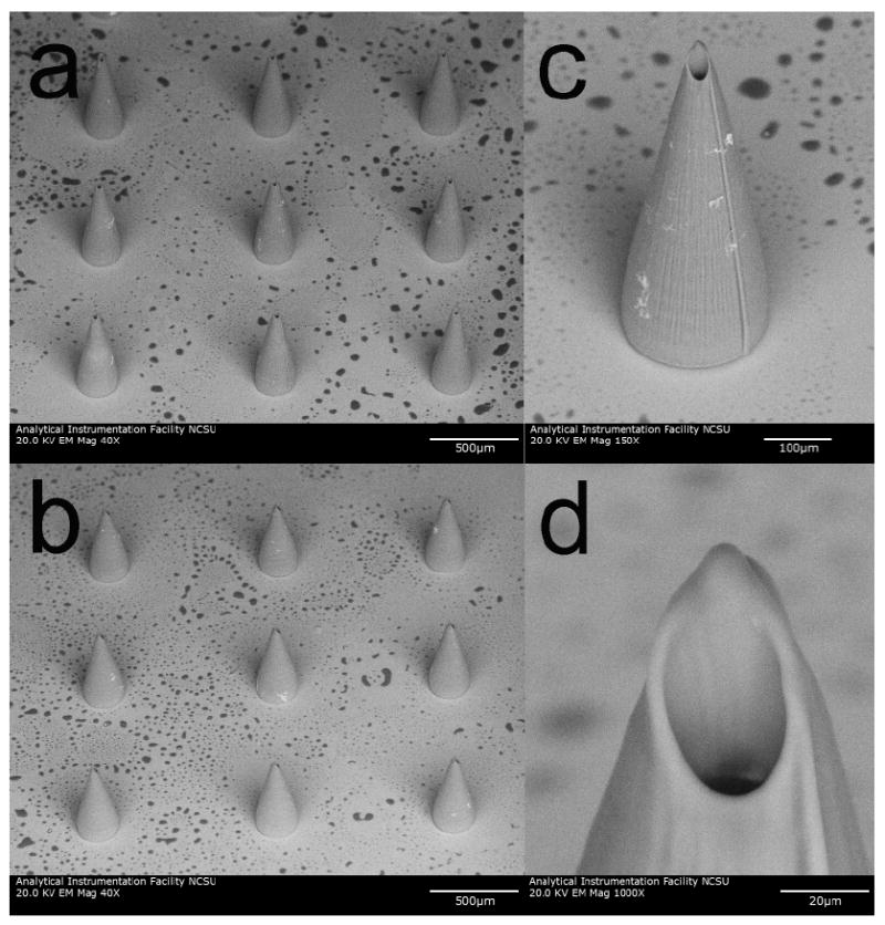
Figure 7 contains scanning electron microscopy images of a freestanding microneedle array, containing both the substrate and the microneedles. These microneedles exhibited a measured height of 508 +/- 33 μm and a measured diameter of 212 +/- 3 μm (Figure 7a and Figure 7b). No discontinuities were observed at the interfaces between the microneedles and the substrate (Figure 7c). It should be noted that the microneedle structure shown in Figure 7a, which was produced with a 5× objective, exhibits less precise small-scale features than the microneedle structure shown in Figure 6a, which was produced with a 10× objective. It is interesting to note that the measured base diameter obtained using the 10× objective was smaller than the input file base diameter; this finding was attributed to shrinkage of the material during polymerization. On the other hand, the measured base diameter obtained using the 5× objective was larger than the input file base diameter; this finding was attributed to the fact that the voxel size exceeds the material shrinkage. The nonuniform “pillow top”-like morphology of the substrate was attributed to radial laser energy degradation. Minimized processing time and minimized processing cost are obtained by performing two photon polymerization using the most rapid possible write speed. Objective election and mark speed are two of several laser-material interaction parameters that can be readily altered to produce structures with optimized geometries using two photon polymerization.
Figure 7.

Scanning electron microscopy images of e-shell 300 hollow microneedle array, which was produced using two photon polymerization. a) Image of microneedle array obtained at 45° tilt. b) Image of individual microneedle obtained at 45° tilt. c) Image of individual microneedle obtained at 0° tilt. The length and base diameters of these microneedles are 508 +/- 33 μm and 212 +/- 3 μm, respectively. Dimensions are shown as average +/- standard deviation.
Multiphoton microscopy was used to observe quantum dot delivery into porcine skin via a two photon polymerization-fabricated e-shell 300 microneedle array as well as via topical application. Z-stack images of a microneedle in porcine skin prior to quantum dot injection (Figure 8a), a microneedle in porcine skin after quantum dot injection (Figure 8b), and quantum dots topically applied to porcine skin (Figure 8c) are shown. The microneedles are presented as surface renderings (in gray) and the quantum dots are presented as maximum projections (in red). Thresholding values for surface renderings were 62.800 μm2 for the z-stack images of the microneedle in porcine skin prior to quantum dot injection and 35.040 μm2 for the z-stack images of the microneedle in porcine skin after quantum dot injection.
Figure 8.
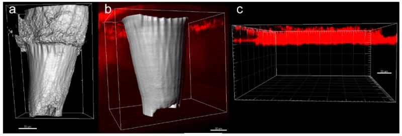
Multiphoton microscopy images of quantum dot injection via two photon polymerization-fabricated e-shell 300 microneedle array as well as via topical application. The microneedles are presented as surface renderings (in gray) and the quantum dots are presented as maximum projections (in red). a) Microneedle in porcine skin prior to quantum dot injection. b) Microneedle in porcine skin after quantum dot injection. A broad distribution of the quantum dots in the deep epidermis and dermis was observed. c) Quantum dots topically applied to porcine skin. The topically applied quantum dots exhibited poor penetration and remained in the topmost 50 μm region of the epidermis.
The e-shell 300 acrylate-based polymer was noted to fluoresce under multiphoton excitation; the use of e-shell 300 or similar materials may be beneficial for transdermal theranostics activities involving multiphoton microscopy. Since time is needed to acquire Z-stack image data and adjust image acquisition settings, quantitative time-dependent data on quantum dot movement over time was unable to be obtained. Another drawback of the multiphoton microscopy setup involved the use of a water immersion lens, which required a water column between the objective and the sample. Water was placed on the backside of the microneedle array. It is possible that capillary forces in the channels pulled some of the water through the microneedles and even into the skin, resulting in dilution of quantum dot solution. Refraction from the skin resulted in reduced image quality from deep tissue regions; neither the e-shell 300 acrylate-based microneedles nor the quantum dots could be imaged beyond a depth of ∼500 μm from the skin surface. Levene et al. recently demonstrated the use of gradient index lenses with needle-like dimensions for multiphoton microscopy with subcellular resolution; in vivo images of quantum dots within tissues that were several millimeters within an anesthetized, intact murine model (e.g., hippocampal tissue and cortical layer tissue) were obtained.55
The topically applied quantum dots exhibited poor penetration; they remained in the topmost 50 μm region of the epidermis. Ryman-Rasmussen et al. investigated topical administration of Qdot® 565 ITK™ carboxyl quantum dots; the carboxyl quantum dots were shown to penetrate the stratum corneum and primarily localize in the epidermis by eight hours; fluorescence intensity maps suggested that penetration occurred by means of a passive diffusion mechanism.54 They suggested that quantum dot penetration by carboxylic acid-coated quantum dots (hydrodynamic size=14 nm) occurred by means of diffusion within the intracellular space. After being pressed against the skin, the microneedles penetrated to nearly their full length. After quantum dot injection via the microneedle array, broad distribution of the quantum dots in the deep epidermis and dermis was observed. Quantum dots administered via microneedle injection were well distributed within fifteen minutes. Quantum dots were also observed in between the microneedles and the skin; this finding was attributed to migration of the quantum dot solution along the microneedle-created pores. In previous work, Gittard et al. used solid e-Shell 200 acrylate-based polymer microneedle arrays to create pores in human stratum corneum and epidermis. Optical imaging of the microneedle-created pores revealed that they were irregular in shape and were smaller than the microneedle dimensions; this finding was attributed to anisotropic tensile forces associated with collagen and other skin tissue components.33 The small microneedle channel dimensions may enable precise delivery of a theranostics agent.
Conclusions
In this study, we demonstrated that two-photon polymerization can be used to produce a freestanding microneedle array, containing both the substrate and the microneedles. The e-shell 300 acrylate-based polymer microneedles successfully created pores in the stratum corneum layer, which enabled administration of the quantum dot solution to the deep epidermis and dermis. Microneedles enabled more rapid distribution of quantum dots to deep epidermal and dermal layers of porcine skin than topical administration. Multiphoton microscopy enabled imaging of quantum dots as well as microneedles within the skin; this approach may be useful for theranostics applications involving a variety of tissues. The ability to transdermally deliver quantum dots by means of microneedles is advantageous for theranostics applications due to the fact that microneedles are associated with minimal pain sensation, injection site trauma, and injection site inflammation. Two photon polymerization may be used to fabricate microneedles with patient-specific use, including (a) use for depth-dependent transdermal delivery and (b) use for delivery of quantum dots as well as for withdrawal of blood and/or interstitial fluid. It is anticipated that microneedles fabricated by means of two photon polymerization may enable precise transport of theranostics agents into epidermal, dermal, or subdermal tissues.
References
- 1.Picard FJ, Bergeron MG. Drug Discov Today. 2002;7:1092–1101. doi: 10.1016/S1359-6446(02)02497-2. [DOI] [PubMed] [Google Scholar]
- 2.Warner S. Scientist. 2004;18:38–39. [Google Scholar]
- 3.Bissonnette L, Bergeron MG. Expert Rev Mol Diagn. 2006;6:433–450. doi: 10.1586/14737159.6.3.433. [DOI] [PubMed] [Google Scholar]
- 4.Debbage P, Jaschke W. Histochem Cell Biol. 2008;130:845–875. doi: 10.1007/s00418-008-0511-y. [DOI] [PubMed] [Google Scholar]
- 5.Sumer B, Gao J. Nanomed. 2008;3:137–140. doi: 10.2217/17435889.3.2.137. [DOI] [PubMed] [Google Scholar]
- 6.Roland D. Personalized Med. 2007;4:439–444. doi: 10.2217/17410541.4.4.439. [DOI] [PubMed] [Google Scholar]
- 7.Bruchez M, Moronne M, Gin P, Weiss S, Alivisatos AP. Science. 1998;281:2013–2016. doi: 10.1126/science.281.5385.2013. [DOI] [PubMed] [Google Scholar]
- 8.Niemeyer CM. Angew Chem -Int Edit. 2001;40:4128–4158. doi: 10.1002/1521-3773(20011119)40:22<4128::AID-ANIE4128>3.0.CO;2-S. [DOI] [PubMed] [Google Scholar]
- 9.Klarreich E. Nature. 2001;413:450–452. doi: 10.1038/35097256. [DOI] [PubMed] [Google Scholar]
- 10.Seydel C. Science. 2003;300:80–81. doi: 10.1126/science.300.5616.80. [DOI] [PubMed] [Google Scholar]
- 11.Åkerman ME, Chan WCW, Laakkonen P, Bhatia SN, Ruoslahti E. Proc Natl Acad Sci U S A. 2002;99:12617–12621. doi: 10.1073/pnas.152463399. [DOI] [PMC free article] [PubMed] [Google Scholar]
- 12.Peng ZA, Peng XG. J Am Chem Soc. 2001;123:183–184. doi: 10.1021/ja003633m. [DOI] [PubMed] [Google Scholar]
- 13.Michalet X, Pinaud FF, Bentolila LA, Tsay JM, Doose S, Li JJ, Sundaresan G, Wu AM, Gambhir SS, Weiss S. Science. 2005;307:538–544. doi: 10.1126/science.1104274. [DOI] [PMC free article] [PubMed] [Google Scholar]
- 14.Ho Y, Leong KW. Nanoscale. 2010;2:60–68. doi: 10.1039/b9nr00178f. [DOI] [PMC free article] [PubMed] [Google Scholar]
- 15.Tada H, Higuchi H, Wanatabe TM, Ohuchi N. Cancer Res. 2007;67:1138–1144. doi: 10.1158/0008-5472.CAN-06-1185. [DOI] [PubMed] [Google Scholar]
- 16.Derfus AM, Chen AA, Min D, Ruoslahti E, Bhatia SN. Bioconjug Chem. 2007;18:1391–1396. doi: 10.1021/bc060367e. [DOI] [PubMed] [Google Scholar]
- 17.Dwarakanath S, Bruno JG, Shastry A, Phillips T, John A, Kumar A, Stephenson LD. Biochem Biophys Res Commun. 2004;325:739–743. doi: 10.1016/j.bbrc.2004.10.099. [DOI] [PubMed] [Google Scholar]
- 18.Li Y, He Z, Zhang P, Gao J, Cheng C, Zhang H. J Nanosci Nanotechnol. 2010;10:520–524. doi: 10.1166/jnn.2010.1723. [DOI] [PubMed] [Google Scholar]
- 19.Bagalkot V, Zhang L, Levy-Nissenbaum E, Jon S, Kantoff PW, Langer R, Farokhzad OC. Nano Lett. 2007;7:3065–3070. doi: 10.1021/nl071546n. [DOI] [PubMed] [Google Scholar]
- 20.Cai W, Chen X. Nat Prot. 2008;3:89–96. doi: 10.1038/nprot.2007.478. [DOI] [PubMed] [Google Scholar]
- 21.Hagens WI, Oomen AG, de Jong WH, Cassee FR, Sips AJAM. Regul Toxicol Pharmacol. 2007;49:217–229. doi: 10.1016/j.yrtph.2007.07.006. [DOI] [PubMed] [Google Scholar]
- 22.Vega-Villa KR, Takemoto JK, Yanez JA, Remsberg CM, Forrest ML, Davies NM. Adv Drug Deliv Rev. 2008;60:929–938. doi: 10.1016/j.addr.2007.11.007. [DOI] [PubMed] [Google Scholar]
- 23.Gardeniers HJGE, Luttge R, Berenschot EJW, de Boer MJ, Yeshurun SY, Hefetz M, van't Oever R, van den Berg A. J Microelectromech Syst. 2003;12:855–862. doi: 10.1109/JMEMS.2003.080293. [DOI] [Google Scholar]
- 24.Gill HS, Denson DD, Burris BA, Prausnitz MR. Clin J Pain. 2008;24:585–594. doi: 10.1097/AJP.0b013e31816778f9. [DOI] [PMC free article] [PubMed] [Google Scholar]
- 25.Gittard SD, Narayan RJ. In: Toxicology of the Skin. Monteiro-Riviere NA, editor. Informa Healthcare; New York, NY: 2010. pp. 301–316. [Google Scholar]
- 26.Nordquist L, Roxhed N, Griss P, Stemme G. Pharm Res. 2007;24:1381–1388. doi: 10.1007/s11095-007-9256-x. [DOI] [PubMed] [Google Scholar]
- 27.Gittard SD, Ovsianikov A, Chichkov BN, Doraiswamy A, Narayan RJ. Expert Opin Drug Deliv. 2010;7:513–533. doi: 10.1517/17425241003628171. [DOI] [PMC free article] [PubMed] [Google Scholar]
- 28.Coulman SA, Anstey A, Gateley C, Morrissey A, McLoughlin P, Allender C, Birchall JC. Int J Pharm. 2009;366:190–200. doi: 10.1016/j.ijpharm.2008.08.040. [DOI] [PubMed] [Google Scholar]
- 29.McAllister DV, Wang PM, Davis SP, Park JH, Canatella PJ, Allen MG, Prausnitz MR. Proc Natl Acad Sci U S A. 2003;100:13755–13760. doi: 10.1073/pnas.2331316100. [DOI] [PMC free article] [PubMed] [Google Scholar]
- 30.Bal S, Kruithof AC, Liebl H, Tomerius M, Bouwstra J, Lademann J, Meinke M. Laser Phys Lett. 2010;7:242–246. doi: 10.1002/lapl.200910134. [DOI] [Google Scholar]
- 31.Doraiswamy A, Jin C, Narayan RJ, Mageswaran P, Mente P, Modi R, Auyeung R, Chrisey DB, Ovsianikov A, Chichkov B. Acta Biomater. 2006;2:267–275. doi: 10.1016/j.actbio.2006.01.004. [DOI] [PubMed] [Google Scholar]
- 32.Ovsianikov A, Chichkov B, Mente P, Monteiro-Riviere NA, Doraiswamy A, Narayan RJ. Int J Appl Ceram Technol. 2007;4:22–29. [Google Scholar]
- 33.Gittard SD, Ovsianikov A, Monteiro-Riviere NA, Lusk J, Morel P, Minghetti P, Lenardi C, Chichkov BN, Narayan RJ. J Diabetes Sci Technol. 2009;3:304–311. doi: 10.1177/193229680900300211. [DOI] [PMC free article] [PubMed] [Google Scholar]
- 34.Gittard SD, Narayan RJ, Jin C, Ovsianikov A, Chichkov BN, Monteiro-Riviere NA, Stafslien S, Chisholm B. Biofabrication. 2009;1:041001. doi: 10.1088/1758-5082/1/4/041001. [DOI] [PMC free article] [PubMed] [Google Scholar]
- 35.Gittard SD, Ovsianikov A, Akar H, Chichkov B, Monteiro-Riviere NA, Stafslien S, Chisholm B, Shin C, Shih C, Lin S, Su Y, Narayan RJ. Adv Eng Mater. 2010;12:B77–B82. doi: 10.1002/adem.200980012. [DOI] [PMC free article] [PubMed] [Google Scholar]
- 36.Doraiswamy A, Ovsianikov A, Gittard SD, Monteiro-Riviere NA, Crombez R, Montalvo E, Shen W, Chichkov BN, Narayan RJ. J Nanosci Nanotechnol. 2010 doi: 10.1166/jnn.2010.2636. in press. [DOI] [PubMed] [Google Scholar]
- 37.Gittard SD, Narayan RJ. Expert Rev Med Dev. 2010;7:343–356. doi: 10.1586/erd.10.14. [DOI] [PMC free article] [PubMed] [Google Scholar]
- 38.Ovsianikov A, Chichkov B, Adunka O, Pillsbury H, Doraiswamy A, Narayan RJ. Appl Surf Sci. 2007;253:6603–6607. doi: 10.1016/j.apsusc.2007.01.062. [DOI] [Google Scholar]
- 39.Weissleder R, Pittet MJ. Nature. 2008;452:580–589. doi: 10.1038/nature06917. [DOI] [PMC free article] [PubMed] [Google Scholar]
- 40.Wang PM, Cornwell M, Prausnitz MR. Diabetes Technol Ther. 2005;7:131–141. doi: 10.1089/dia.2005.7.131. [DOI] [PubMed] [Google Scholar]
- 41.Kim Y, Ludovice PJ, Prausnitz MR. J Controlled Release. 2007;122:375–383. doi: 10.1016/j.jconrel.2007.05.031. [DOI] [PMC free article] [PubMed] [Google Scholar]
- 42.Choi S, Kim Y, Park J, Hutcheson J, Gill H, Yoon Y, Prausnitz M, Allen M. Biomed Microdev. 2010;12:263–273. doi: 10.1007/s10544-009-9381-x. [DOI] [PMC free article] [PubMed] [Google Scholar]
- 43.Maffia P, Zinselmeyer BH, Ialenti A, Kennedy S, Baker AH, McInnes IB, Brewer JM, Garside P. Circulation. 2007;115:E326–E328. doi: 10.1161/CIRCULATIONAHA.106.658492. [DOI] [PubMed] [Google Scholar]
- 44.Stroh M, Zimmer JP, Duda DG, Levchenko TS, Cohen KS, Brown EB, Scadden DT, Torchilin VP, Bawendi MG, Fukumura D, Jain RK. Nat Med. 2005;11:678–682. doi: 10.1038/nm1247. [DOI] [PMC free article] [PubMed] [Google Scholar]
- 45.Larson DR, Zipfel WR, Williams RM, Clark SW, Bruchez MP, Wise FW, Webb WW. Science. 2003;300:1434–1436. doi: 10.1126/science.1083780. [DOI] [PubMed] [Google Scholar]
- 46.Lee HA, Imran M, Monteiro-Riviere NA, Colvin VL, Yu WW, Riviere JE. Nano Lett. 2007;7:2865–2870. doi: 10.1021/nl071563c. [DOI] [PubMed] [Google Scholar]
- 47.Frank S. A New Model for European Medical Device Regulation: A Comparative Legal Analysis in the EU and the USA. Europa Law Publishing; Groningen: 2003. pp. 15–69. [Google Scholar]
- 48.Oliver WC, Pharr GM. J Mater Res. 1992;7:1564–1583. [Google Scholar]
- 49.Mosmann T. J Immunol Methods. 1983;65:55–63. doi: 10.1016/0022-1759(83)90303-4. [DOI] [PubMed] [Google Scholar]
- 50.Grant CG, Warren R, Salter E. Burns. 1980;7:57–69. [Google Scholar]
- 51.Khatri CA, Stansbury JW, Schultheisz CR, Antonucci JM. Dent Mater. 2003;19:584–588. doi: 10.1016/S0109-5641(02)00108-2. [DOI] [PubMed] [Google Scholar]
- 52.Park H, Allen MG, Prausnitz MR. J Controlled Release. 2005;104:51–66. doi: 10.1016/j.jconrel.2005.02.002. [DOI] [PubMed] [Google Scholar]
- 53.Park JH, Prausnitz MR. J Korean Phys Soc. 2010;4:122–1227. doi: 10.3938/jkps.56.1223. [DOI] [PMC free article] [PubMed] [Google Scholar]
- 54.Ryman-Rasmussen JP, Riviere JE, Monteiro-Riviere NA. Toxicol Sci. 2006;91:159–165. doi: 10.1093/toxsci/kfj122. [DOI] [PubMed] [Google Scholar]
- 55.Levene MJ, Dombeck DA, Kasischke KA, Molloy RP, Webb WW. J Neurophysiol. 2004;91:1908–1912. doi: 10.1152/jn.01007.2003. [DOI] [PubMed] [Google Scholar]