Abstract
By revisiting the air distribution and bioaerosol dispersion in Ward 8A where the largest nosocomial severe acute respiratory syndrome (SARS) outbreak occurred in Hong Kong in 2003, we found an interesting phenomenon. Although all the cubicles were in ‘positive pressure’ towards the corridor, the virus-containing bioaerosols generated from the index patient's cubicle were still transmitted to other cubicles, which cannot be explained in a traditional manner. A multi-zone model combining the two-way airflow effect was used to analyse this phenomenon. The multi-zone airflow model was evaluated by our experimental data. Comparing with the previous computational fluid dynamic simulation results, we found that the air exchange owing to the small temperature differences between cubicles played a major role in SARS transmission. Additionally, the validated multi-zone model combining the two-way airflow effect could simulate the pollutant transport with reasonable accuracy but much less computational time. A probable improvement in general ward design was also proposed.
Keywords: two-way airflow, temperature difference, severe acute respiratory syndrome transmission, multi-zone model, indoor environment
1. Introduction
Hospital-acquired infection is an important public health issue with unacceptable levels of morbidity and mortality. While contact transmission of disease forms the majority of hospital-acquired infection cases, transmission through the air is harder to control than other transmission routes [1,2]. Respiratory infections can be spread via indirect contact with droplets from expiratory activities such as breathing, coughing and sneezing, and many studies have investigated the size distribution of human-exhaled droplets [3–13]. Since the engineering sciences can play an important role in limiting airborne disease transmission [1,2], many engineering control methods such as ventilation have been well studied [14–17]. The hospital-acquired infection of severe acute respiratory syndrome (SARS) was one of the most significant disease transmission cases in the first decade of the twenty-first century.
Following the first reported case of infection in Guangdong, China, in the spring of 2003, a total of 1755 people in Hong Kong were diagnosed with SARS [18]. A 26-year-old Hong Kong resident who contracted the infection was treated in Ward 8A at the Prince of Wales Hospital, which subsequently led to the largest nosocomial SARS outbreak in Hong Kong [19]. Several epidemiological studies have investigated the spread of SARS in Ward 8A for different groups of patients: Lee et al. [19] for healthcare workers; Wong et al. [20] for medical students; and Yu et al. [21] for inpatients.
Although the primary SARS virus was mostly spread by close personal contact and large-droplet transmission [22], there is strong evidence suggesting that the virus can spread through the airborne route [23–25]. In the Ward 8A case, Lee et al. [19] and Wong et al. [20] also indicated that close personal contact and large-droplet transmission were the main routes of SARS transmission. Yu et al. [21] indicated that airborne transmission was also an important route of SARS transmission. Furthermore, Li et al. [26] investigated the role of air distribution in SARS transmission in Ward 8A. They performed computational fluid dynamic (CFD) simulations and field measurements to analyse the bioaerosol dispersion in Ward 8A and demonstrated the significance of air distribution control in hospital wards in preventing the transmission of diseases, based on the association between the predicted bioaerosol dispersion pattern and spatial infection pattern.
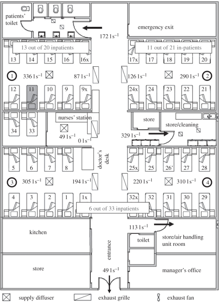
Revisiting the air distribution and bioaerosol dispersion in Ward 8A by Li et al. [26], we found an interesting phenomenon. As shown in figure 1, all the supply diffusers were installed in the cubicles, while all the exhaust grilles were installed in the corridor. Thus, to common knowledge, all the cubicles should be in ‘positive pressure’ towards the corridor, which means the airborne bioaerosols generated by the index patient who stayed in cubicle 1 would have no chance to enter other cubicles. However, the epidemiological data showed that the inpatients that stayed in other cubicles were also infected. So how did these virus-containing bioaerosols transmit to other positive-pressure rooms? Revisiting the CFD results of air distribution in Ward 8A by Li et al. [26], a two-way airflow pattern existed at the opening (width × height: 6 × 2.4 m2) between cubicles and corridor, as shown in figure 2. The CFD results of temperature distribution (fig. 6 in [26]) showed that the temperature in the corridor was slightly higher than those in the cubicles. So may the thermal pressure effect caused by temperature difference be a suspected mechanism for the two-way airflow pattern at the opening? CFD simulation is a good approach for obtaining detailed information of air distribution, and many researchers have used the CFD approach to study the hospital-acquired infection [27–34]. CFD allows us to evaluate each geometrical and ventilation parameter on dispersion of virus-laden particles; however, CFD is also more expensive to run in terms of computer cost when compared with other simpler analysis methods for airflow. This paper presents a multi-zone model combining the two-way airflow effect to re-analyse the case of SARS transmission in Ward 8A. Experimental data were obtained by carrying out the experiments in an environmental chamber with a mechanical ventilation system to validate the multi-zone model. We demonstrated the role of air exchange owing to temperature difference in SARS transmission. Additionally, based on the multi-zone modelling and analysis, an improvement in designing general hospital wards was proposed.
Figure 1.
Floor plan of Ward 8A during the time of the outbreak in March 2003. There were four large cubicles, each with 10 beds. Measured supply and exhaust flow rates by Li et al. [26] are shown for each diffuser/grille. The bed (no. 11) where the index patient stayed is also marked. The numbers of inpatients who developed SARS in each cubicle are also marked (revised based on fig. 1 in [26]).
Figure 2.
Velocity vectors in a vertical plane in the middle of the cubicles at the time of outbreak (made by Li et al. [26]).
2. Modelling methods
2.1. Multi-zone model combing two-way airflow effect
Similar to the CFD simulations by Li et al. [26], our computational domain included all four cubicles, the nurses' station and the corridor, as well as the entrance. The isolation cubicle, toilets, store, kitchen and the manager's office were excluded in the computational domain. Each cubicle was set as an individual zone, while the corridor was divided into two zones with the same area. The nurses' station was included in the top zone of corridor.
Our multi-zone model is based on mass balance of airflow, energy, bioaerosols and the pressure relationship between each zone and opening. According to the results of CFD simulations (figs 5 and 6 in [26]), the air temperature distribution in the cubicle was of the mixing type [26]. Thus, we neglected the influence of vertical temperature stratification and assumed that the cubicle air was well mixed. Another major assumption for the multi-zone model is that the effect of air viscosity and turbulent flow was not explicitly considered, rather being considered in the flow resistance coefficients. Since the temperature difference between cubicles and corridor may result in two opposite directions of airflow existing at the opening, the airflow rate from cubicles to corridor and from corridor to cubicles through the opening should be calculated. The mass balance equation of airflow in each zone can be expressed as:
 |
2.1 |
where Qi,in is the inflow rate while Qi,out is the outflow rate (m3 h−1).
The height of Ward 8A, H, is 2.4 m. The elevation (y) of H/2 = 1.2 m was assumed as the reference elevation of the opening between two adjacent, j and k, zones, y = 0. The pressure at y in j and k zones can be calculated by
| 2.2 |
and
| 2.3 |
where g is the gravitational acceleration (m s−2). ρj and ρk are the air density in j and k zones (kg m−3), respectively. The neutral height, Y, is at the position where the air velocity is zero, which is equivalent to the following equation:
| 2.4 |
When |Y| < H/2, assuming the j zone is in overall positive pressure towards the k zone, the relationship between airflow and pressure difference at the opening can be described as [35]
 |
2.5 |
and
 |
2.6 |
where Δρ is the air density difference between j and k zones (owing to the temperature difference). W is the width of the openings, which is 6 m for cubicles' opening and 3 m for opening between corridors 1 and 2. The shape of the openings was assumed as a rectangle, which matches the real case. Cd is the discharge coefficient of the opening, which is set at 0.78, as the experiments by Weber & Kearney [36] have shown this value works well for most applications. However, it is known that the discharge coefficient for large openings such as doorways and windows is difficult to determine. If |Y|≥ H/2, there is no two-way airflow existing at the door opening. In this case, slightly different formulae are needed [37].
The energy balance equation for each zone can be expressed as
 |
2.7 |
where cp is the specific heat capacity (J (kg K)−1); Ti is the temperature of the inflow at the supply diffusers, exhaust grilles or openings (K); T is the temperature of this zone (K); and S is the heat gain in each zone (W). It was assumed that the heat gain was uniformly distributed in a zone.
As discussed by Li et al. [26], the virus-containing bioaerosols can be modelled as a passive tracer since the water droplets evaporated rapidly after release and became very fine [11,38,39]. For comparing with the CFD results by Li et al. [26], this assumption was also used in this study. Therefore, the bioaerosol mass balance equation for each zone (except for cubicle 1) can be expressed as
 |
2.8 |
where Ci is the normalized bioaerosol concentration of the inflow at the supply diffusers, exhaust grilles or openings, and C is the normalized bioaerosol concentration of this zone. It was assumed that the bioaerosol was uniformly distributed in a zone.
2.2. Boundary conditions
All the boundary conditions were set similar to that of the CFD simulation used by Li et al. [26]. All the airflows at supply diffusers and exhaust grilles are marked in figure 1. The main boundary conditions of the CFD simulation by Li et al. [26] are summarized in table 1. The CFD and measurement results of bioaerosol concentrations were normalized by the concentration in the source patient's bed, and the results show that the normalized bioaerosol concentration in cubicle 1 was approximately 0.03. Thus, for comparing with CFD simulation results by Li et al. [26], the normalized bioaerosol concentration in cubicle 1, Ccub,1, was set at 0.03 as a reference concentration. The air temperature at the supply diffuser was 14.3°C. The total heat gain was 11.64 kW; including 2.232 kW because of lighting, 2.964 kW because of 39 patients (76 W each, only sensible heat from a person is included) and 6.444 kW uniformly distributed on the floor, were used in this study. The detailed data are as follows: (i) lighting: 0.399 kW for each cubicle zone, 0.319 kW for each corridor zone, (ii) patients: 0.76 kW for cubicle 1, 2 and 4 zones, and 0.684 kW for cubicle 3 zone, 0 kW for corridor zones, and (iii) heat gain uniformly distributed on the floor: 1.151 kW for each cubicle zone, 0.920 kW for each corridor zone.
Table 1.
Summary of the main boundary conditions of the CFD simulation in Li et al. [26].
| zones | airflow rate at supply diffusers (l s−1)a | airflow rate at exhaust grilles (l s−1)a | airflow rate at other openings (l s−1)a | supply air temperature (°C) | total heat gain (kW) |
|---|---|---|---|---|---|
| cubicle 1 | 336 | n.a. | n.a. | 14.3 | 2.310 |
| cubicle 2 | 290 | n.a. | n.a. | 14.3 | 2.310 |
| cubicle 3 | 305 | n.a. | n.a. | 14.3 | 2.234 |
| cubicle 4 | 310 | n.a. | n.a. | 14.3 | 2.310 |
| corridor | 49 | 627 | 663 | 14.3 | 2.478 |
aThe detailed information is shown in figure 1.
3. Model validation
3.1. Experimental set-up
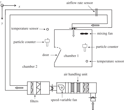
To validate the multi-zone model combing the two-way airflow effect, experiments were carried out in an environmental chamber. The experimental configuration is illustrated schematically in figure 3. Chamber 1, which is 2 × 2 × 2 m3 and made of stainless steel, simulated the cubicle, while the surrounding chamber 2 simulated the corridor in Ward 8A. A mechanical ventilation system with a variable speed fan was installed to control the air parameters inside chamber 1. The ventilation pattern was set as supply-only pattern, which means supply airflow can only exit from the door. This design simulated the ventilation situation of cubicles in Ward 8A, which was supposed to be positive pressure. The dimensions of the inlet are 250 × 250 mm2, while the dimensions of the door are 0.6 × 1.6 m2 (width (W) × height (H)). The opening degree of the door was set as 90° (totally open) to simulate the opening between cubicle and corridor in Ward 8A.
Figure 3.
Experimental schematic.
Four frequencies of the fan were tested out in the experiments—10, 20, 30 and 40 Hz—corresponding air change rates: 27.0, 52.4, 98.5 and 131.9 ACH. Before each experiment, the surfaces of the indoor chamber were cleaned up to avoid the influence of particle resuspension. We also checked the effectiveness of the mixing fan through measuring the particle concentration distribution in the chamber before the formal experiments and made sure that the chamber air was well mixed. At the beginning of each experiment, the air in the indoor chamber was diluted by the ventilation system for half an hour to avoid the influence of initial particle concentration. Then, the particle concentrations at the inlet were measured. Each experiment was carried out for 30 min to make sure the steady condition was reached. The particle concentrations at indoors and outdoors, supply air velocity in the duct, and pressure difference between indoor and outdoor were continuously measured during the whole period. The airflow directions under each supply airflow rate were measured using visible smoke in repeated independent experiments. If the visible smoke that was generated in chamber 2 could transport into chamber 1, the airflow direction at the door was two-way. There was no specific particle source. The particles that were naturally suspended in the air were used as the measurement objects. Chamber 2 was a relatively steady environment without any activity and particle sources. These ensured the particle concentrations in chamber 2 were relatively steady. This assumption matches with our measurement results. Temperatures indoors and outdoors were also continuously measured during the whole period. Since each experiment was carried out at different periods, the temperatures in indoor and outdoor chambers were different in each experiment. These variable temperature differences contained different cases for the thermal pressure effect, which help to provide more useful experimental data for model validation.
Two FLUKE 983 optical particle counters (FLUKE Inc., Everett, WA, USA) were used to measure the particle concentrations. FLUKE 983 simultaneously measures and records six channels of particle sizes (0.3–0.5, 0.5–1.0, 1.0–2.0, 2.0–5.0, 5.0–10.0 and ≥10.0 µm). The counter has a coincidence loss of 5 per cent when the particle concentration is two million particles per cubic inch and a 100 per cent counting efficiency when the measured particle diameter is larger than 0.45 µm [40]. The counters had been calibrated by the manufacturer and also calibrated prior to each measurement using a zero-counter filter. The particle concentration was measured in the same location using the two counters to check whether they were consistent. The two FLUKE 983 particle counters can also be used to measure the temperature with a precision of 0.1°C. A KIMO PM200 differential pressure meter (KIMO Inc. Bordeaux, France) with a precision of 1 Pa was used to measure the pressure difference between indoor and outdoor environments. An air velocity sensor with a precision of 0.01 m s−1 was installed near the inlet for measuring the supply airflow rate.
3.2. Measured data and model validation
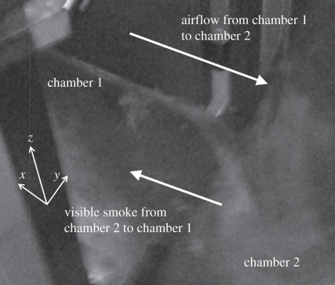
The measured temperatures of chambers 1 and 2, supply airflow rates, pressure differences and airflow directions are summarized in table 2. When the opening degree was quite large, the pressure difference was too small to be measured, which was shown as zero on the differential pressure meter. The temperature difference in each experiment varied from 0.6 to 6.0°C, and the supply airflow rate in each experiment varied from 216 to 1055 m3 h−1. Based on the airflow direction test using visible smoke, all airflow directions at the door were two-way. As shown in figure 4, the airflow (visible smoke) from chamber 2 transported to chamber 1 at the low area of the door. Since the indoor temperature was higher than the outdoor temperature in each experiment, which matches with the airflow direction test (cooler air would transport to the warmer side through the low area), the experimental results indicated that the thermal pressure affects the transport of particles to some extent. Therefore, it seems that the mechanical ventilation system was too weak to maintain absolute positive pressure and prevent particles in chamber 2 entering chamber 1 owing to the impact of two-way airflow caused by a thermal pressure effect in these cases.
Table 2.
Chamber 1 and chamber 2 temperatures, supply airflow rates and airflow direction in each experiment.
| fan frequency (Hz) | chamber 1 temperature (°C) | chamber 2 temperature (°C) | temperature difference (°C) | supply airflow rate (m3 h−1) | airflow directiona |
|---|---|---|---|---|---|
| 10 | 29.6 | 29.0 | 0.6 | 216 | two-way |
| 20 | 20.8 | 16.0 | 4.8 | 491 | two-way |
| 30 | 26.9 | 21.9 | 5.0 | 788 | two-way |
| 40 | 25.0 | 19.0 | 6.0 | 1055 | two-way |
aTwo-way means two opposite airflow directions exist, and the flow from chamber 2 to chamber 1 all exist at the lower area of the door.
Figure 4.
Photograph of the airflow direction test. The visible smoke that was generated in chamber 2 transported into chamber 1, which means that the airflow direction at the door was two-way. The arrows at the low area of the door represent the direction of airflow (visible smoke) from chamber 2 to chamber 1. The arrows at the upper area of the door represent the direction of airflow from chamber 1 to chamber 2.
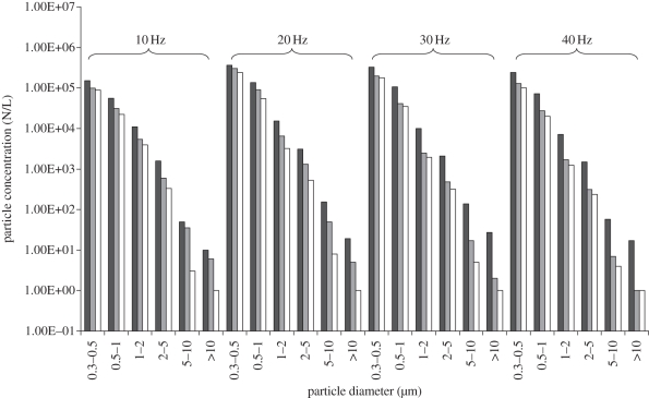
Chambers 1 and 2 and supply particle concentrations are summarized in figure 5. Since the concentrations of particles with a diameter larger than 5 µm were quite low, only the concentration data of particles with a diameter in the range of 0.3–5 µm were selected for validation. For further validating the model, the influence of particle deposition in chamber 1 was also taken into consideration. The deposition velocity has been well reviewed by Lai [41]. Since the air exchange rate was quite large in the experiments, the deposition velocities were chosen in the summary by Lai [41] for large air exchange rate: 1.5e − 04 m s−1 for 0.3 − 0.5 µm, 2.0e − 04 m s−1 for 0.5 − 1 µm, 5.0e − 04 m s−1 for 1 − 2 µm and 6.0e − 04 m s−1 for 2 − 5 µm. The comparison of experimental data and calculated data of indoor particle concentrations is summarized in table 3. The mean (s.d.) relative error between the analysis model and experimental data was 9.3 ± 5.8%. Therefore, the model was well validated. Table 4 shows the airflow rates and corresponding air change rates at the supply inlet and the door opening in the validation experiments. It can be found that the air exchange owing to temperature difference at the door opening was quite significant.
Figure 5.
Chamber 1 (dark grey bars), chamber 2 (light grey bars) and supply air particle concentrations (white bars) (N/L, number per litre).
Table 3.
Comparison of experimental data and calculated data of indoor particle concentrations.
| fan frequency (Hz) | particle size (µm) | experimental data (N/La) | calculated data (N/L a) | errorb (%) |
|---|---|---|---|---|
| 10 | 0.3–0.5 | 9.78E + 04 | 9.79E + 04 | 0.2 |
| 0.5–1 | 3.09E + 04 | 2.77E + 04 | 10.2 | |
| 1–2 | 5.40E + 03 | 4.74E + 03 | 12.2 | |
| 2–5 | 5.97E + 02 | 5.09E + 01 | 14.7 | |
| 20 | 0.3–0.5 | 3.04E + 05 | 2.84E + 05 | 6.7 |
| 0.5–1 | 9.00E + 04 | 8.45E + 04 | 6.1 | |
| 1–2 | 6.46E + 03 | 7.59E + 03 | 17.5 | |
| 2–5 | 1.30E + 03 | 1.44E + 03 | 10.7 | |
| 30 | 0.3–0.5 | 1.98E + 05 | 1.97E + 05 | 0.6 |
| 0.5–1 | 4.12E + 04 | 4.37E + 04 | 6.0 | |
| 1–2 | 2.48E + 03 | 2.89E + 03 | 16.4 | |
| 2–5 | 4.80E + 02 | 5.28E + 02 | 10.0 | |
| 40 | 0.3–0.5 | 1.28E + 05 | 1.08E + 05 | 15.4 |
| 0.5–1 | 2.73E + 04 | 2.32E + 04 | 15.1 | |
| 1–2 | 1.70E + 03 | 1.58E + 03 | 6.8 | |
| 2–5 | 3.10E + 02 | 3.08E + 02 | 0.5 | |
| total: mean (s.d.) | 9.3 ± 5.8 | |||
aN/L, number per litre.
b where Cin,exp is the experimental data of indoor particle concentration, and Cin,cal is the calculated data of indoor particle concentration.
Table 4.
The airflow rates and corresponding air change rates at the supply inlet and the door opening in the validation experiments.
| fan frequency (Hz) | supply airflow rate (m3 h−1) | corresponding air change rate (ACH) | airflow rate from chamber 2 to 1 at the door opening (m3 h−1) | corresponding air change rate (ACH) |
|---|---|---|---|---|
| 10 | 216 | 27.0 | 59 | 7.4 |
| 20 | 491 | 52.4 | 276 | 34.5 |
| 30 | 788 | 98.5 | 121 | 15.1 |
| 40 | 1055 | 131.9 | 77 | 9.6 |
4. Results and discussion
4.1. Comparison of multi-zone and computational fluid dynamic simulations
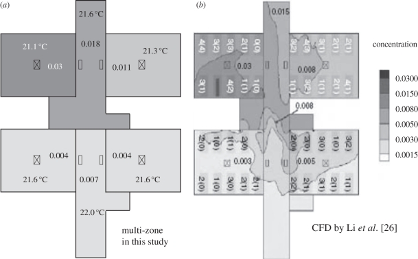
Figure 6 shows the comparison of bioaerosol distributions using the multi-zone model and the CFD approach. It can be found that the results by these two approaches match quite well. Since the CFD approach used in the case of Ward 8A had been validated by Li et al. [26] using their experimental data, the CFD results could be regarded as reliable, which means the results by the multi-zone model combining the two-way airflow effect presented in this study are also reliable. As discussed by Li et al. [26], the supply ceiling jets had ensured a rather uniform distribution of bioaerosols in each cubicle. Therefore, regarding each cubicle as one zone was reasonable. For the corridor, since its geometry was long and narrow and it had many airflow inlets and outlets, it should be divided into several parts. According to our test, dividing the corridor into two parts was accurate enough for simulation in this Ward 8A case using the multi-zone model combining the two-way airflow effect. Furthermore, taken into account for the calculation cost and difficulty, the multi-zone model is more convenient and suitable for engineers. Therefore, the multi-zone model combining the two-way airflow effect may be a better simulation approach owing to its convenience and enough accuracy for actual application.
Figure 6.
Comparison of results of bioaerosol distributions using multi-zone and CFD simulations. The concentrations have been normalized.
It should be noticed that if the air in the room was not well mixed, the error of the multi-zone model would significantly increase. For instance, if the vertical temperature stratification was quite significant, which indicated the room was not well mixed, the calculation error of the air exchange owing to temperature difference at the door openings using the multi-zone model would increase. Additionally, if the geometry of the door openings was complicated, it was difficult to accurately calculate the airflow rate at the door openings using the multi-zone model. Therefore, there are also some limitations in the general use of the multi-zone model presented in this study.
4.2. Effect of air exchange owing to temperature difference
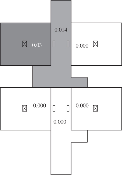
If the air temperature in each zone was the same, the bioaerosol distribution would be presented as shown in figure 7. Only cubicle 1 and corridor 1 contained bioaerosols since other cubicles were absolutely positive pressure. Therefore, it seems that the effect of air exchange owing to temperature difference was one of the dominating influencing factors in SARS transmission in Ward 8A. All the two-way airflow rates at each opening are summarized in table 5, which shows that the two-way airflows were significant. These two-way airflows destroyed the positive pressure in each cubicle and resulted in stronger air exchange between zones. As shown in figure 6, the temperature differences between adjacent zones were in the range of 0.3–0.5°C. According to equations (2.5) and (2.6), the air density difference owing to temperature difference between zones and the area of the opening were two factors that decided the magnitude of the two-way air exchange. Therefore, such a small temperature difference could cause a large air exchange between rooms owing to the relatively large area of the openings.
Figure 7.
Bioaerosol distributions using the multi-zone model when the air temperatures in all the zones are the same. The concentrations have been normalized.
Table 5.
Airflow rates at the openings.
| openings | direction | airflow rate (l s−1) |
|---|---|---|
| cubicle 1 versus corridor 1 | cubicle 1 to corridor 1 | 921 |
| corridor 1 to cubicle 1 | 586 | |
| cubicle 2 versus corridor 1 | cubicle 2 to corridor 1 | 729 |
| corridor 1 to cubicle 2 | 440 | |
| cubicle 3 versus corridor 2 | cubicle 3 to corridor 2 | 825 |
| corridor 2 to cubicle 3 | 520 | |
| cubicle 4 versus corridor 2 | cubicle 4 to corridor 2 | 828 |
| corridor 2 to cubicle 4 | 518 | |
| corridor 1 versus corridor 2 | corridor 1 to corridor 2 | 378 |
| corridor 2 to corridor 1 | 418 |
There is a general misconception among the public, i.e. if a room only has supply airflow or supply airflow is larger than return airflow, then this room should be absolute positive pressure since the superfluous airflow must move out from the room. However, the air distribution in Ward 8A is a strong and representative case to disprove this judgement. When the area of the opening is relatively large, even a small temperature difference can result in two-way airflow at the opening, which destroys the positive pressure. In the perspective of virus-containing bioaerosol transmission, this two-way airflow effect owing to temperature difference is quite significant in this case, since it can turn a protective environment into a highly risky one. Therefore, the role of air exchange owing to temperature difference in virus-containing bioaerosol transmission should be given special attention. However, if more routes of transmission exist and the relative influence is also more significant, the evaluation for the importance of each influencing factor on SARS transmission should be balanced accordingly.
There have been some studies focusing on the impact of door-opening motion on the spread of contaminants [1,2,42]. They suggested that the air exchange caused by doors opening/closing motion has been previously identified as a risk of infection. Therefore, avoiding the exchange of doorway airflow is quite important for controlling airborne infection.
Li et al. [26] also suggested that airflow imbalance is one of the reasons for bioaerosol spread, but the impact is relatively small. Figure 8 shows the results of an airflow balance case using the multi-zone model combining the two-way airflow effect. Comparing figure 8 with figure 6, it can be found that the difference between the balance and imbalance cases is quite small, which agrees with the conclusion by Li et al. [26].
Figure 8.
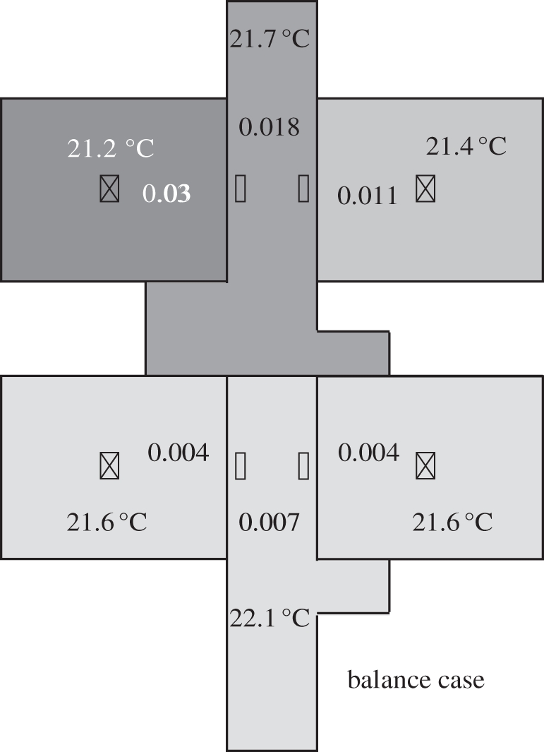
Bioaerosol distributions using the multi-zone model for the airflow balance case. The concentrations have been normalized.
Besides, in the real case, the influence of a person's movements may be another transmission route. There may be three mechanisms of the SARS transmission by the person's movements: (i) the person's movements cause close personal contact and large-droplet transmission, which are the main routes of SARS transmission; (ii) the virus-containing bioaerosols deposit on the person's surfaces and get transported to other rooms, becoming airborne owing to resuspension, and then enter into the breathing zone of the patients; (iii) the person's movements across the door opening cause the transport of corridor air containing bioaerosols to the other cubicles and result in the SARS transmission. Additionally, the residual turbulence generated in the corridor may be sufficient to cause the transport of corridor air containing bioaerosols to the other cubicles and lead to infection. However, inclusion of human movement will unlikely change the conclusion of this study as the movement could only introduce more mixing in the cubicles. The amount of air exchange owing to a person's movement is significantly small when compared with the air exchange owing to temperature differences.
4.3. Probable improvement of general ward design
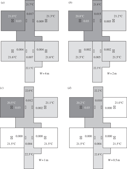
Based on the simulation and analysis, the role of air exchange owing to temperature difference in SARS transmission during the nosocomial outbreak in Ward 8A was quite significant. Therefore, avoiding air exchange owing to temperature difference is one of the key points for avoiding virus transmission from one zone to another. Since the temperature differences between adjacent zones were already quite small, the only way to avoid the air exchange owing to temperature difference is reducing the area of the openings. For instance, curtains can be installed at the openings of all the cubicles, and eventually the area of the openings can be reduced. Figure 9 shows the comparison of bioaerosol distributions using the multi-zone model when the widths of the openings (W) were 4, 2, 1 and 0.5 m, respectively. Following the decrease in the area of the openings, the bioaerosol transmission between each zone became weaker. When the width of the openings was 0.5 m, the bioaerosol concentrations in cubicles 2, 3 and 4 were almost zero. Therefore, reducing the area of the openings, e.g. installing curtains, is an effective approach for reducing the magnitude of SARS transmission in Ward 8A. Ching et al. [43] also suggested that the use of hospital curtains could reduce the risk of hospital-acquired infection between patients, and a curtain fully extended to the full length yielded a much better infection control performance than a partially extended curtain. However, hospital curtains may cause inconvenience for the healthcare workers, which is a disadvantage.
Figure 9.
Bioaerosol distributions using the multi-zone model. (a) the width of the opening was 4 m; (b) the width of the opening was 2 m; (c) the width of the opening was 1 m; (d) the width of the opening was 0.5 m. The concentrations have been normalized.
Li et al. [26] investigated the effectiveness of a new hypothetical ventilation system, which included a dedicated downward supply diffuser for each bed, with four supply diffusers over the aisle between the two rows of beds in each cubicle. They found that it performs relatively well in Ward 8A: the concentration in cubicle 2 was reduced to between 0.003 and 0.005, while in cubicles 3 and 4 to between 0 and 0.003. This is a very effective design that can obviously reduce the concentrations of other cubicles. Nevertheless, this design needs a lot of supply diffusers and exhaust grilles, which may have a big impact on the final cost. By contrast, installing curtains at the openings to reduce the area of the openings could be more convenient and economical.
5. Conclusions
Revisiting the role of air distribution in SARS transmission during the large nosocomial outbreak in Ward 8A, we found that the two-way airflow effect at the openings plays an important role in bioaerosols transmission. The most likely reason for the two-way airflow effect may be the thermal pressure effect. This paper aimed to investigate the role of air exchange owing to temperature difference in SARS transmission in Ward 8A using a validated multi-zone model combining the two-way airflow effect. Within the scope of this research, the following conclusions can be drawn:
— air exchange owing to temperature difference played a significant role in SARS transmission during the nosocomial outbreak in Ward 8A;
— the validated multi-zone model combining the two-way airflow effect may be a better simulation approach than CFD owing to its convenience and accuracy for actual application; and
— reducing the area of the openings between cubicles and corridor (e.g. installing curtains at the openings) may be a more convenient and economical improvement on general ward design.
Acknowledgements
This study was sponsored by the National Natural Science Foundation of China (grant no. 51078216) and supported by Tsinghua University Initiative Scientific Research Programme.
References
- 1.Eames I., Tang J. W., Li Y., Wilson P. 2009. Airborne transmission of disease in hospitals. J. R. Soc. Interface 6, S697–S702 10.1098/rsif.2009.0407.focus (doi:10.1098/rsif.2009.0407.focus) [DOI] [PMC free article] [PubMed] [Google Scholar]
- 2.Eames I., Shoaib D., Klettner C. A., Taban V. 2009. Movement of airborne contaminants in a hospital isolation room. J. R. Soc. Interface 6, S757–S766 10.1098/rsif.2009.0319.focus (doi:10.1098/rsif.2009.0319.focus) [DOI] [PMC free article] [PubMed] [Google Scholar]
- 3.Chao C. Y. H., et al. 2009. Characterization of expiration air jets and droplet size distributions immediately at the mouth opening. J. Aerosol Sci. 40, 122–133 10.1016/j.jaerosci.2008.10.003 (doi:10.1016/j.jaerosci.2008.10.003) [DOI] [PMC free article] [PubMed] [Google Scholar]
- 4.Duguid J. F. 1945. The numbers and the sites of origin of the droplets expelled during expiratory activities. Edin. Med. J. 52, 335–340 [PMC free article] [PubMed] [Google Scholar]
- 5.Jennison M. W. 1942. Aerobiology, pp. 106 Washington, DC: American Association of Advanced Science [Google Scholar]
- 6.Loudon R. G., Roberts R. M. 1967. Relation between the airborne diameters of respiratory droplets and the diameter of the stains left after recovery. Nature 213, 95–96 10.1038/213095a0 (doi:10.1038/213095a0) [DOI] [Google Scholar]
- 7.Morawska L. 2006. Droplet fate in indoor environments, or can we prevent the spread of infection? Indoor Air 16, 335–347 10.1111/j.1600-0668.2006.00432.x (doi:10.1111/j.1600-0668.2006.00432.x) [DOI] [PubMed] [Google Scholar]
- 8.Morawska L., Johnson G. R., Ristovski Z. D., Hargreaves M., Mengersen K., Corbett S., Chao C. Y. H., Li Y., Katoshevski D. 2009. Size distribution and sites of origin of droplets expelled from the human respiratory tract during expiratory activities. J. Aerosol Sci. 40, 256–269 10.1016/j.jaerosci.2008.11.002 (doi:10.1016/j.jaerosci.2008.11.002) [DOI] [PMC free article] [PubMed] [Google Scholar]
- 9.Nicas M., Nazaroff W. W., Hubbard A. 2005. Toward understanding the risk of secondary airborne infection: emission of respirable pathogens. J. Occup. Environ. Hyg. 2, 143–154 10.1080/15459620590918466 (doi:10.1080/15459620590918466) [DOI] [PMC free article] [PubMed] [Google Scholar]
- 10.Papineni R. S., Rosenthal F. S. 1997. The size distribution of droplets in the exhaled breath of healthy human subjects. J. Aerosol Med. 10, 105–116 10.1089/jam.1997.10.105 (doi:10.1089/jam.1997.10.105) [DOI] [PubMed] [Google Scholar]
- 11.Wells W. F. 1934. On air-borne infection. Study II. Droplets and droplet nuclei. Am. J. Hyg. 20, 611–618 [Google Scholar]
- 12.Xie X., Li Y., Sun H., Liu L. 2009. Exhaled droplets due to talking and coughing. J. R. Soc. Interface 6, S703–S714 10.1098/rsif.2009.0388.focus (doi:10.1098/rsif.2009.0388.focus) [DOI] [PMC free article] [PubMed] [Google Scholar]
- 13.Yang S., Lee G. W. M., Chen C. M., Wu C. C., Yu K. P. 2007. The size and concentration of droplets generated by coughing in human subjects. J. Aerosol Med. 20, 484–494 10.1089/jam.2007.0610 (doi:10.1089/jam.2007.0610) [DOI] [PubMed] [Google Scholar]
- 14.Li Y., et al. 2007. Role of ventilation in airborne transmission of infectious agents in the built environment: a multidisciplinary systematic review. Indoor Air 17, 2–18 10.1111/j.1600-0668.2006.00445.x (doi:10.1111/j.1600-0668.2006.00445.x) [DOI] [PubMed] [Google Scholar]
- 15.Nielsen P. V. 2009. Control of airborne infectious diseases in ventilated spaces. J. R. Soc. Interface 6, S747–S755 10.1098/rsif.2009.0228.focus (doi:10.1098/rsif.2009.0228.focus) [DOI] [PMC free article] [PubMed] [Google Scholar]
- 16.Pantelic J., Sze To G. N., Tham K. W., Chao C. Y. H., Khoo Y. C. M. 2009. Personalized ventilation as a control measure for airborne transmissible disease spread. J. R. Soc. Interface 6, S715–S726 10.1098/rsif.2009.0311.focus (doi:10.1098/rsif.2009.0311.focus) [DOI] [PMC free article] [PubMed] [Google Scholar]
- 17.Tang J. W., Liebner T. J., Craven B. A., Settles G. S. 2009. A schlieren optical study of the human cough with and without wearing masks for aerosol infection control. J. R. Soc. Interface 6, S727–S736 10.1098/rsif.2009.0295.focus (doi:10.1098/rsif.2009.0295.focus) [DOI] [PMC free article] [PubMed] [Google Scholar]
- 18.WHO 2003. Summary of probable SARS cases with onset of illness (from 1 November 2002 to 31 July 2003: revised 26 September 2003). See http://www.who.int/csr/sars/country/table2003_09_23/en/)
- 19.Lee N., et al. 2003. A major outbreak of severe acute respiratory syndrome in Hong Kong. New Engl. J. Med. 348, 1986–1994 10.1056/NEJMoa030685 (doi:10.1056/NEJMoa030685) [DOI] [PubMed] [Google Scholar]
- 20.Wong T. W., et al. 2004. Cluster of SARS among medical students exposed to single patient, Hong Kong. Emerg. Infect. Dis. 10, 269–276 [DOI] [PMC free article] [PubMed] [Google Scholar]
- 21.Yu I. T. S., Wong T. W., Chiu Y. L., Lee N., Li Y. 2005. Spatio-temporal analysis of SARS among hospital inpatients. Clin. Infect. Dis. 40, 1237–1243 10.1086/428735 (doi:10.1086/428735) [DOI] [PMC free article] [PubMed] [Google Scholar]
- 22.WHO 2003. Consensus document on the epidemiology of severe acute respiratory syndrome (SARS). See http://www.who.int/csr/sars/en/WHOconsensus.pdf
- 23.Christian M. D., et al. & SARS Investigation Team 2004. Possible SARS coronavirus transmission during cardiopulmonary resuscitation. Emerg. Infect. Dis. 10, 287–293 [DOI] [PMC free article] [PubMed] [Google Scholar]
- 24.Jiang Y., Zhao B., Li X., Yang X., Zhang Z., Zhang Y. 2009. Investigating a safe ventilation rate for the prevention of indoor SARS transmission: an attempt based on a simulation approach. Build. Simul. 2, 281–289 10.1007/s12273-009-9325-7 (doi:10.1007/s12273-009-9325-7) [DOI] [PMC free article] [PubMed] [Google Scholar]
- 25.Yu I. T. S., Li Y. G., Wong T. W., Tam W., Chan A., Lee J. H. W., Leung D. Y. C., Ho T. 2004. Evidence of airborne transmission of severe acute respiratory syndrome virus. New Engl. J. Med. 350, 1731–1739 10.1056/NEJMoa032867 (doi:10.1056/NEJMoa032867) [DOI] [PubMed] [Google Scholar]
- 26.Li Y., Huang X., Yu I. T. S., Wong T. W., Qian H. 2005. Role of air distribution in SARS transmission during the largest nosocomial outbreak in Hong Kong. Indoor Air 15, 83–95 10.1111/j.1600-0668.2004.00317.x (doi:10.1111/j.1600-0668.2004.00317.x) [DOI] [PubMed] [Google Scholar]
- 27.Beggs C. B., Kerr K. G., Noakes C. J., Hathway E. A., Sleigh P. A. 2008. The ventilation of multiple-bed hospital wards: review and analysis. Am. J. Infect. Cont. 36, 250–259 10.1016/j.ajic.2007.07.012 (doi:10.1016/j.ajic.2007.07.012) [DOI] [PubMed] [Google Scholar]
- 28.Chao C. Y. H., Wan M. P., Sze To G. N. 2008. Transport and removal of expiratory droplets in hospital ward environment. Aerosol Sci. Technol. 42, 377–394 [Google Scholar]
- 29.Chen C., Zhao B., Cui W., Dong L., An N., Ouyang X. 2010. The effectiveness of an air cleaner in controlling droplet/aerosol particle dispersion emitted from a patient's mouth in the indoor environment of dental clinics. J. R. Soc. Interface 7, 1105–1118 10.1098/rsif.2009.0516 (doi:10.1098/rsif.2009.0516) [DOI] [PMC free article] [PubMed] [Google Scholar]
- 30.Chow T. T., Yang X. Y. 2005. Ventilation performance in the operating theatre against airborne infection: numerical study on an ultra-clean system. J. Hosp. Infect. 59, 138–147 10.1016/j.jhin.2004.09.006 (doi:10.1016/j.jhin.2004.09.006) [DOI] [PubMed] [Google Scholar]
- 31.Kao P. H., Yang R. J. 2006. Virus diffusion in isolation rooms. J. Hosp. Infect. 62, 338–345 10.1016/j.jhin.2005.07.019 (doi:10.1016/j.jhin.2005.07.019) [DOI] [PMC free article] [PubMed] [Google Scholar]
- 32.Qian H., Li Y., Nielsen P. V., Hyldgaard C. E., Wong T. W., Chwang A. T. Y. 2006. Dispersion of exhaled droplet nuclei in a two-bed hospital ward with three different ventilation systems. Indoor Air 16, 111–128 10.1111/j.1600-0668.2005.00407.x (doi:10.1111/j.1600-0668.2005.00407.x) [DOI] [PubMed] [Google Scholar]
- 33.Richmond-Bryant J. 2009. Transport of exhaled particulate matter in airborne infection isolation rooms. Build. Environ. 44, 44–55 [DOI] [PMC free article] [PubMed] [Google Scholar]
- 34.Zhao B., Yang C., Chen C., Feng C., Yang X., Sun L., Gong W., Yu L. 2009. How many airborne particles emitted from a nurse will reach the breathing zone/body surface of the patient in ISO Class-5 single-bed hospital protective environments?—a numerical analysis. Aerosol Sci. Technol. 43, 990–1005 [Google Scholar]
- 35.CONTAMW 2002. CONTAMW user's manual, National Institute of Standards and Technology. Gaithersburg, MD: NIST [Google Scholar]
- 36.Weber D. D., Kearney R. J. 1980. Natural convective heat transfer through an aperture in passive solar heated buildings. 5th National Passive Solar Conference, pp. 1037–1041, Amherst, MA [Google Scholar]
- 37.Li Y., Delsante A., Symons J. 2000. Prediction of natural ventilation in buildings with large openings. Build. Environ. 35, 191–206 10.1016/S0360-1323(99)00011-6 (doi:10.1016/S0360-1323(99)00011-6) [DOI] [Google Scholar]
- 38.Chen C., Zhao B. 2010. Some questions on dispersion of human exhaled droplets in ventilation room: answers from numerical investigation. Indoor Air 20, 95–111 10.1111/j.1600-0668.2009.00626.x (doi:10.1111/j.1600-0668.2009.00626.x) [DOI] [PubMed] [Google Scholar]
- 39.Xie X., Li Y., Chwang A. T. Y., Ho P. L., Seto W. H. 2007. How far droplets can move in indoor environments: revisiting the Wells evaporation–falling curve. Indoor Air 17, 211–225 10.1111/j.1600-0668.2007.00469.x (doi:10.1111/j.1600-0668.2007.00469.x) [DOI] [PubMed] [Google Scholar]
- 40.FLUKE Inc 2005. Manual for FLUKE 983 optical particle counter. Everett, WA: FLUKE Inc [Google Scholar]
- 41.Lai A. C. K. 2002. Particle deposition indoors: a review. Indoor Air 12, 211–214 10.1046/j.0905-6947.2002.1r159a.x (doi:10.1046/j.0905-6947.2002.1r159a.x) [DOI] [PubMed] [Google Scholar]
- 42.Tang J. W., Eames I., Li Y., Taha Y. A., Wilson P., Bellingan G., Ward K. N., Breuer J. 2005. Door-opening motion can potentially lead to a transient breakdown in negative-pressure isolation conditions: the importance of vorticity and buoyancy airflows. J. Hosp. Infect. 61, 283–286 10.1016/j.jhin.2005.05.017 (doi:10.1016/j.jhin.2005.05.017) [DOI] [PMC free article] [PubMed] [Google Scholar]
- 43.Ching W. H., Leung M. K. H., Leung D. Y. C., Li Y., Yuen P. L. 2008. Reducing risk of airborne transmitted infection in hospitals by use of hospital curtains. Indoor Built. Environ. 17, 252–259 10.1177/1420326X08091957 (doi:10.1177/1420326X08091957) [DOI] [Google Scholar]


