Abstract
Bioactive hydroxyapatite (HA) with addition of silicon (Si) in the crystal structure (silicon-doped hydroxyapatite (SiHA)) has become a highly attractive alternative to conventional HA in bone replacement owing to the significant improvement in the in vivo bioactivity and osteoconductivity. Nanometre-scaled SiHA (nanoSiHA), which closely resembles the size of bone mineral, has been synthesized in this study. Thus, the silicon addition provides an extra chemical cue to stimulate and enhance bone formation for new generation coatings, and the next stage in metallic implantation design is to further improve cellular adhesion and proliferation by control of cell alignment. Topography has been found to provide a powerful set of signals for cells and form contact guidance. Using the recently developed novel technique of template-assisted electrohydrodynamic atomization (TAEA), patterns of pillars and tracks of various dimensions of nanoSiHA were achieved. Modifying the parameters of TAEA, the resolution of pattern structures was controlled, enabling the topography of a substrate to be modified accordingly. Spray time, flow rate and distance between the needle and substrate were varied to improve the pattern formation of pillars and tracks. The 15 min deposition time provided the most consistent patterned topography with a distance of 50 mm and flow rate of 4 µl min−1. A titanium substrate was patterned with pillars and tracks of varying widths, line lengths and distances under the optimized TAEA processing condition. A fast bone-like apatite formation rate was found on nanoSiHA after immersion in simulated body fluid, thus demonstrating its high in vitro bioactivity. Primary human osteoblast (HOB) cells responded to SiHA patterns by stretching of the filopodia between track and pillar, attaching to the apex of the pillar pattern and stretching between two. HOB cells responded to the track pattern by elongating along and between the track, and the length of HOB cells was proportional to the gaps between track patterns, but this relationship was not observed on the pillar patterns. The study has therefore provided an insight for future design of next generation implant surfaces to control and guide cellular responses, while TAEA patterning provides a controllable technique to provide topography to medical implants.
Keywords: patterning, electrohydrodynamic atomization, surface topography
1. Introduction
Metallic implants have been widely used in major load-bearing applications, such as hip prostheses and dental implants owing to their excellent mechanical properties, but the osteoconductivity is generally lacking in metallic materials, resulting in slow bond formation with bone. The osteoconductive and osseointegrative nature of hydroxyapatite, Ca10(PO4)6(OH)2 (HA), has made it a popular coating material for metallic orthopaedic implants for over two decades [1]. HA-coated metallic prostheses, which combine the osteoconductivity of HA and high strength of metal alloys, have been increasingly favoured by surgeons for younger patients seeking joint replacements, particularly considering the ageing global population.
Recently, it has been demonstrated that the in vivo bioactivity of HA can be significantly improved with the incorporation of silicate into the HA structure, silicon-substituted hydroxyapatite (SiHA) [2,3]. Carlisle [4] demonstrated that silicon is an essential mineral for growth and skeletal development and a Si-deficient diet causes significantly diminished weight gain, cartilage and bone development.
By the addition of a small amount of silicon (1 wt%) to HA, the bioactivity of SiHA has been increased [5]. SiHA has a greater rate of in vivo dissolution, in comparison with that of HA [6] as well as a greater rate of bone apposition [3]. The primary effect of Si in bone and cartilage is thought to be associated with matrix synthesis, although its influence on calcification may be an indirect phenomenon from matrix components [7]. Silicon has been found to promote collagen type 1 synthesis, which constitutes 90 per cent of extracellular matrix (ECM), enhance osteoblast differentiation [8] and prevent poor host bone metabolism in defect repair [2]. The exact mechanism of the effect of Si incorporation has yet to be elucidated. The role of Si in the HA structure may be active, where Si ions are released into the ECM, thus affecting the rate of bone apposition, or Si could act in a passive capacity, where the addition of the Si to the HA alters the chemistry and grain size, indirectly changing the biological response as the dissolution preferentially occurred at grain boundaries and triple junctions. Both active (increase in solubility and release of Si) and passive (favourable topography from increased grain boundaries with decrease in the grain size) roles of Si in HA leads to the increasing bioactivity of SiHA. Therefore, SiHA is a highly attractive alternative to conventional HA in bone replacement, for example successful bone graft in spinal fusion. A range of techniques has been described recently for coating SiHA as a new generation implant, which provides an extra chemical cue to stimulate and enhance bone formation [9–11].
In addition to varying the chemistry of the coating, the next logical stage in optimizing metallic implantation design is to further improve the target cell adhesion and proliferation by controlling the cell alignment, thus improving the rate at which bone tissue regenerates. Topography has been found to provide a powerful set of signals for cells [12], inferring enhanced adhesion, accelerated cell movement and orientation. Controlling cell direction, orientation and proliferation rates is of paramount importance in the success of an implant as it not only enables a decrease in implant fixation time, but also enables cells to grow preferentially in one area to strengthen fixation in desired areas. Therefore, the design of the implant surface is crucial to promote the acceptance of implants by surrounding tissue and, ultimately, extend the functional service life of the implant.
Cellular interaction varies with cell type, feature size and geometry, materials chemistry and fabrication methods. Microcontact printing [13], ink jet printing [14], anisotropic etching [15], chemical vapour deposition [16], photolithography [17] and electron-beam lithography [18] have been developed to produce a variety of surface patterns of microwells, channels, grooves, islands, ridges and pits. Recently, template-assisted electrohydrodynamic atomization (TAEA) spraying of nano hydroxyapatite (nanoHA) has been developed as a new way to pattern the implant surface for guided cell growth [19,20]. TAEA has been developed from the well-documented technique of electrohydrodynamic atomization (EHDA). This technique has the advantages of low cost, easy set-up and operation in ambient temperature and pressure and versatility, where a wide variety of materials, from metal, polymer, ceramic to composite, can be processed. The equipment system set-up consists of a nozzle connected to high voltage and ground electrode. nanoHA suspension was fed through at a precisely controlled flow rate and subjected to a high voltage and droplets of nanoHA were generated under the stable jetting. The droplets were attracted to the grounded substrate to release the charge, and the deposition of nanoHA was achieved once the solvent has evaporated. Previous work has shown that human osteoblast (HOB) cells were aligned along and across the nanoHA pattern prepared by TAEA [20]. In order to achieve more rapid bone apposition, patterning of implant surface with highly bioactive nanoSiHA is the approach to create a desired surface topography for ‘contact guidance’. In this study, patterning of highly bioactive nanoSiHA was attempted by firstly constructing a flow rate-applied voltage map for TAEA processing, secondly, optimizing a range of processing parameters and finally assessing the in vitro cellular responses to the various patterns created.
2. Material and methods
2.1. Preparation and characterization of nanoSiHA
NanoSiHA (with 1 wt% Si) was synthesized based on the reaction between calcium hydroxide and orthophosphoric acid (AnalaR grade, BDH, UK). Tetraethoxysilane (TEOS) was used for the incorporation of Si while Ca/(Si + P) ratios were maintained at 1.67, as detailed in table 1. Under continuous stirring at ambient temperature (20°C), P and Si solution was added dropwise to the Ca solution; pH was kept above 10.5 by the addition of ammonia solution. Continuous stirring was maintained for 16 h after the addition of reactants. The nanocrystals obtained were further aged and washed with boiling water. Ethanol (AnalaR grade) was used to disperse the particles for preparation of nanoHA and nanoSiHA suspension for electrohydrodynamic atomization (EA) spraying.
Table 1.
Reagents used for making nSiHA.
| reagent | 0 wt%SiHA(M) | 1.0 wt% nanoSiHA (M) |
|---|---|---|
| Ca(OH)2 | 0.5 | 0.5 |
| H3PO4 | 0.3 | 0.282 |
| TEOS | 0 | 0.018 |
| Ca/P | 1.67 | 1.77 |
| Ca/(P + Si) | 1.67 | 1.67 |
The morphology of nanoSiHA was examined using a JEOL 200CX transmission electron microscope. The crystal structures was analysed using a Bruker X-ray diffractometer (D8). The data were collected from 20° to 40° and a scan time of 3600 s was used.
2.2. TAEA processing
The TAEA process set-up has been previously described [21]. Briefly, a stainless steel needle (Stanley engineering LTD, Birmingham, UK) was set in resin for rigidity and insulation, the internal and external diameter was 800 and 1100 µm, respectively. The needle was connected via a conducting cable to a high-voltage power supply (Glassman Europe Ltd., Tadley, UK), and was also connected to a syringe mounted on a programmable infusion pump (Harvard Apparatus) via silicone rubber tubing. A high-speed digital camera (Weinberger AG, Dietikon, Switzerland) in conjunction with a computer was used to observe and characterize the processing and capture images.
Glass slides and titanium alloy (Ti-6Al-4V; cut down to 10 × 10 mm) were used as the substrates for various patterns. Ti alloy plates were polished using silicon carbide grinding paper (up to p4000) to ensure similar surface roughness. Both substrates were washed and cleaned with ethanol and then acetone before TAEA deposition.
A specifically designed ground electrode configuration was used for the TAEA process, which was covered with a single crystal silicon wafer on a metal plate. A range of copper templates, square mesh and track lines were placed on the surface of glass or Ti substrate.
For EA processing, once a specific liquid or suspension is being pumped through the needle capillary and voltage is applied to the capillary, an electric field is immediately set up across the capillary and the grounded plate. The geometries of the jet and subsequent droplets generated are classified into different modes of spraying by micro-dripping, cone-jet, multi-jet, etc. [22]. The stable cone-jet mode, the steadiest mode of spraying, could regularize the break-up of jet to generate fine and uniform droplets, and is therefore the most desirable mode. The cone-jet mode for EA spraying can be obtained within a range of applied voltage at a chosen flow rate. Therefore, the first step for TAEA processing was constructing a map for the stable cone-jet mode by the establishment of the relationship between the flow rate and the corresponding applied voltage. A freshly prepared nanoSiHA suspension was syringed through the needle at a controlled flow rate varied systemically from 2 to 30 µl min−1, and the applied voltage was changed up to 6.0 kV.
The parameters governing TAEA influence the spray produced and are voltage, flow rate, spray time and distance between nozzle and substrate. So the second step was to determine the optimum distance between the substrates and nozzle. This distance was varied from 10 to 60 mm. Another consideration is the spray area, as the onset voltage for stable cone jet and the spray area are directly proportional to the nozzle–substrate distance, respectively.
In TAEA, droplets are driven by the electrical field to attach to the substrate. After evaporation of liquid carrier and removing the template, a deposition of well-defined patterns can be achieved on the substrate surface. TAEA is a selective coating process, which produces pre-determined deposition. The thickness of the deposition is related to the spraying time, which was then varied from 5 to 30 min.
2.3. Characterization of nanoSiHA patterns
2.3.1. Microscopy
The nanoSiHA pattern on the glass substrates was imaged using a Nikon ME600 optical microscope. The microstructure of the nanoSiHA patterns on the Ti substrate was further examined using a field emission scanning electron microscopy (FE-SEM, JEOL JSM/6301F). The dimension of the patterns in terms of width and gap was measured using Image analysis (n = 50).
2.3.2. Profilometry
The height of surface patterns was measured using Proscan 2000 (Scantron) laser profilometer. The scan size is 4 × 4 mm with a step size of 20 µm. Matlab was used for post-data acquisition analysis. The effects of template size and spraying time on the surface patterns were compared.
2.4. Acellular in vitro study
Simulated body fluid (SBF K9 [23]), of an ionic concentration similar to that of human blood plasma (142.0 mM Na+, 5.0 mM K+, 1.5 mM Mg2+, 2.5 mM Ca2+, 148.8 mM Cl−, 4.2 mM HCO3−, 1.0 mM PO42–, pH 7.4), has been widely used for the investigation of in vitro bioactivity. SBF K9 was prepared by dissolving reagent-grade NaCl, NaHCO3, KCl, K2HPO4 · 3H2O, MgCl2 · 6H2O, CaCl2 · 2H2O, Na2SO4 and (tris-(CH2OH)2CNH2) into deionized water. The solution was buffered to pH 7.4 at 37°C with 1 M HCl. AnalaR grade chemicals from Aldrich (UK) were used. The SBF solution was sterilized using a 0.22 µm filter (Millipore, Billerica, USA) prior to testing.
NanoSiHA-deposited samples were immersed in 20 ml of SBF at 37°C in an incubator for up to two weeks. The change in surface structure after soaking in SBF was studied using scanning electron microscope (SEM) and energy dispersive X-ray (EDX) analysis.
2.5. In vitro cell culture
A primary HOB cell culture model [24] was used to assess the biological response of nanoSiHA-patterned surfaces. The culture medium was Dulbecco's minimal essential medium (DMEM), supplemented with 10 per cent foetal calf serum, 5 ml of non-essential amino acids, 75 µg ml−1 ascorbic acid, 20 mM l-glutamine, 20 mM 4-(2-hydroxyethyl)-1-piperazineethanesulphonic acid (HEPES) buffer and penicillin G-sodium and streptomycin at 100 U ml−1 each. All reagents for tissue culture were obtained from Sigma (Poole, UK) unless stated otherwise. HOB cells were cultured at 37°C, 95 per cent relative humidity and 5 per cent CO2 until approximately 80 per cent confluency was achieved, then washed with phosphate buffered saline (PBS), and treated with 0.25 per cent porcine trypsin in 10 mM EDTA/PBS. The cell suspension was then centrifuged at 2000g for 5 min at 4°C, the resultant pellet was re-suspended in fresh medium using a 19 gauge. The cell density was determined using a Neubauer Haemocytometer.
NanoSiHA patterns on glass and Ti substrates were sterilized by dry heat at 600°C for 4 h. HOB cells (4 × 10⁴ cells) were then seeded directly onto the nanoSiHA-patterned substrate and incubated at 37°C in a humidified air atmosphere of 5 per cent CO2 for 24 h. The growth of HOB cells on the nanoSiHA patterns on glass substrates was monitored regularly and imaged under an optical microscope.
2.5.1. Immunohistochemistry
After 24 h incubation period, the culture medium was removed by aspiration. Cells on the patterned surfaces were then washed with PBS, fixed in 3.7 per cent (v/v) phosphate-buffered formaldehyde solution for 30 min at 4°C. PBS supplemented with 0.4 per cent (v/v) Triton X-100 and 1 per cent sucrose at 4°C for 10 min. To minimize non-specific binding of the antibodies, the samples were blocked with 1 per cent solution bovine serum albumin in PBS for 10 min. The cells were then stained using 50 mg ml−1 Hoechst 33 258 and phalloidin–fluorescein isothiocyanate (FITC) conjugate (1 : 50; Sigma, Poole, UK) for 1 h at 37°C. The visualization was carried out using a Leica SPII Confocal microscope equipped with a LED Diode laser to excite the Hoechst 33 258 fluorophore at 405 nm. The emission wavelength range chosen was 415–470 nm. The FITC was excited using a HeNe laser at 488 nm (and emission range of 505–535 nm). Visualization was carried out using a Leica HCX PL APO 63x oil immersion lens, with a numerical aperture of 1.4 and pinhole size equivalent to 1 Airy band resolution was used. An overlay was created using the LCSLite software package (Leica, Wetzlar, Germany).
2.5.2. Cell morphology
After 24 h of culture, HOB cells attached to the titanium were fixed with 1.5 per cent gluteraldehyde (Sigma, UK) in 0.1 M sodium cacodylate for 2 h and 1 per cent tannic acid (Agar, UK) for 30 min. Dehydration was performed by a series of ethyl alcohol washes of varying concentrations (20, 30, 40, 50, 60, 70, 90, 96 and 100). The final dehydration was in hexamethyl disilazane (Sigma, UK), followed by air drying. Subsequently, samples were finally sputter coated with gold prior to examining under SEM (Jeol JSM/6301F) at an accelerating voltage of 3 keV and a working distance of 10–15 mm.
3. Results and discussion
3.1. NanoSiHA
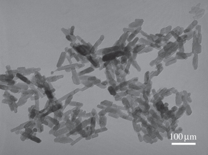
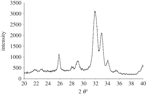
Similar to those of nanoHA particles, nanoSiHA particles produced were rod-like, 20–30 nm in width and 50–80 nm in length (figure 1). X-ray diffraction (XRD) patterns revealed the presence of all the major HA peaks, (002), (211), (300), (202) and (310), and no secondary phases, such as tricalcium phosphate and calcium oxide, were detected (figure 2).
Figure 1.
Transmission electron microscopy micrographs of nanoSiHA particles synthesized for TAEA deposition.
Figure 2.
X-ray diffraction patterns of major HA on electrosprayed nanoSiHA on glass substrate.
3.2. TAEA processing
Achieving the stable cone-jet mode is crucial, as it results in uniform droplet relic deposition on the substrate. TAEA incorporates EHDA technology to create a patterned surface by using a mask template to selectively coat the substrate. The process of TAEA is governed by the key parameters, namely the flow rate of the suspension, the applied voltage, the distance between nozzle and substrate and the spray time, and all these contribute to the pattern produced. It is imperative to construct a map firstly to optimize these parameters to design the implant surface with desired patterns for guiding cells.
3.2.1. Cone-jet map
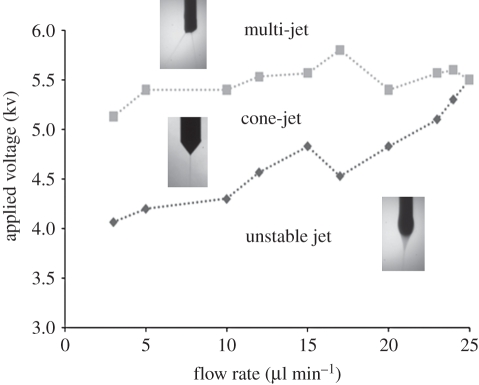
EHDA in cone-jet mode was achieved under the experimental set-up. A strong electric field was built up at the capillary nozzle; the liquid flowing could form a conical shape meniscus when electric driving force was controlled by the applied voltage. The relationships between the flow rate and the voltage applied for EA spraying of nanoHA and nanoSiHA are shown in figure 3. The cone-jet mode was only achieved when the flow rate and the applied voltage were in a distinctive envelope. Above the envelope, a multi-jet was formed for a given flow rate and below the envelope (under the onset applied voltage of cone-jet mode), micro dripping or the unstable cone-jet mode occurred, and the various modes were captured by the high-speed camera, as shown in figure 3. Generally these modes, apart from cone-jet mode, are undesirable as the reproducibility is low and the droplet size is uncontrollable. The maximum flow rate for achieving the stable cone-jet mode for nanoSiHA (25 µl min−1) with the applied voltages all ranged from 4 to 6 KV.
Figure 3.
The relationship between the flow rate and applied voltage (AV) in maintaining the stable cone-jet mode (envelope) during TAEA spraying of 3 wt% nanoSiHA suspensions, the regions above and under the envelope are multi-jet and unstable cone-jet mode. For each flow rate, there is a minimum and maximum voltage value to maintain stable cone-jet mode. Typical jetting pictures for each region are shown. Diamonds with dotted lines, min AV; squares with dotted lines, max AV.
3.2.2. Effects of flow rate
From figure 3, the stable cone-jet mode was maintained over the largest range of applied voltage when the flow rate was from 3 to 20 µl min−1 for nanoSiHA. A low flow rate decreases the velocity of the suspension arriving at the needle tip. This in turn affects the cone and jet formation and consequently the droplet formation during the breaking up of the jet. The ultimate effect is the decrease in the droplet size with lowering the flow rate.
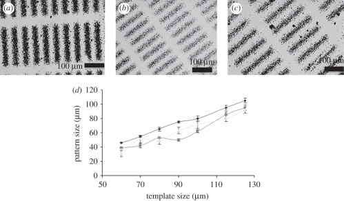
Scattering was significantly reduced when the flow rate decreased from 10 to 4 µl min−1, track and pillar patterns appeared denser, as shown in figure 4. In fact, a flow rate of greater than 7.5 µl min−1 was ineffective in producing clear patterning. Therefore, the resolution of the patterned nanoSiHA was improved with the decrease in flow rate. An even building up of the pattern occurred with smaller relic sizes. Correlation between template size and achieved pattern size in relation to flow rate was established. Lowering the flow rate to 4 µl min−1 provides a linear relationship between template size and resulting pattern (figure 4d) with increased coverage of template space, from 62 per cent of coverage at a flow rate of 6 µl min−1 to that of 80 per cent at the flow rate 4 µl min−1.
Figure 4.
Optical microscopy images of track patterns prepared by TAEA processing at the flow rate of (a) 4 µl min−1; (b) 5 µl min−1; (c) 6 µl min−1; (d) relationship between template size and measured pattern size with the flow rates varied from 4 to 6 ml min−1.
However, when the template dimension decreases, percentages of the nanoSiHA coverage decreased to the point where only 50 per cent of the original width (area) covered. This is due to the smaller gaps with the more copper metal template, a stronger attraction of the particles to deposit on the template.
3.2.3. Effect of the distance from nozzle to the substrate
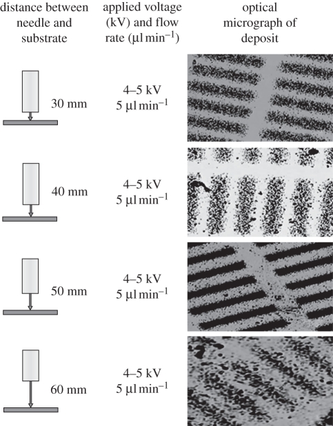
Increasing the distance from nozzle to substrate caused the intensity of nanoSiHA spray on the substrate to vary. The distance which allowed for the heaviest build up was 50 mm (figure 5). The difference of pattern morphology related to the distance between nozzle and substrate is directly linked to droplet flight time and solvent evaporation.
Figure 5.
The effect of the distance between nozzle and substrate, increased from 20 to 60 mm, on the track patterns prepared by TAEA.
The droplet size of the suspension decreased with the increase in the distance between nozzle and substrate, owing to the evaporation of the solvent (ethanol) during transit. The longer the transit time, the longer time the solvent is exposed to the air and increased evaporation takes place. Li et al. [19,21] determined the optimum distance between capillary and substrate is 20 mm for the coating of nanoHA. But in our study, a clear pattern could not be established with a distance below 30 mm. However, for the application of patterning production, there is a stronger emphasis on the specific placement of droplets rather than a complete covering of the substrate surface. From figure 5, the distance of 50 mm was the optimum distance between nozzle exit and substrate for TAEA spraying of 3 wt% nanoSiHA.
3.2.4. Effect of spray time
Under the TAEA deposition optimized in the study, namely, with a flow rate of 4 µl min−1, applied voltage of 4.8 (±0.1) KV, and the distance between substrate and nozzle of 50 mm, the building up of the pillar patterns with spraying time is shown in figure 6. The best outcome for the spraying time was 15 min. When the spraying time was greater than 20 min, scattering became severe and the boundaries of the pattern disappeared.
Figure 6.
The morphology of pillar pattern with spraying time varied from (a) 5 min, (b) 10 min to (c) 15 min.
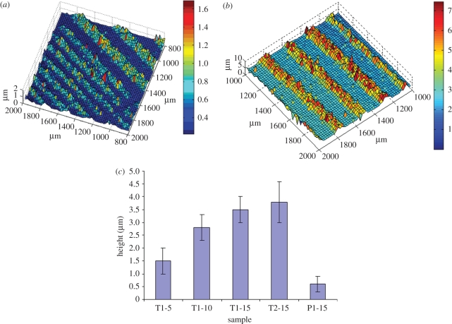
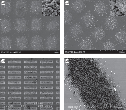
The height of the track pattern increased with the spraying time, figure 7, shows a clear three-dimensional overview of the profiles of the track patterns sprayed for 5 and 15 min. Further comparison of the spraying time and variation in template is shown in figure 6. The height of the short track pattern was 1.5 µm after spraying for 5 min; there was a nearly linear increase with spraying time up to 10 min. The height built up was slowed down up to 15 min, and there was no significant difference in the height of short and long track sprayed for 15 min; however, the height of pillar pattern was almost fivefold less than that of track one. The contour view of a 15 min sprayed track pattern showed that the majority of the track to be of the height of 3 µm, indicating uniform deposition. High-resolution SEM imaging (figure 8) shows that there was a gradual increase in height from the edge to the middle of the pattern. The ‘uneven’ deposition in the template space is owing to the droplets being attracted to the metal template, thus a number of droplets will be attached to the template instead of the space between the templates. This led to high-intensity deposition in the centre of the template space. Well-defined nanoSiHA patterns were successfully achieved using TAEA (figure 8). Analysis indicates that heat treatment of 600°C does not affect the morphology or structure of the patterns on the titanium substrate. Tracks produced have widths of 10, 15 and 25 µm with distances between tracks 60, 100 and 100 µm, respectively.
Figure 7.
Three-dimensional profile of track pattern created by TAEA, spraying for (a) 5 and (b) 15 min. (c) The effect of spraying time variation (from 5 to 15 min) on the height of various patterns (T1-short track, T2-long track, P1-pillar).
Figure 8.
SEM micrographs of pillar pattern (a) before heat treatment and (b) heat treated; (c) track pattern; (d) higher magnification of track pattern; (e) track produced under optimized parameters (insert shows high magnification of deposited SiHA).
3.3. Acellular in vitro study
A rapid and simple in vitro test is required to predict the in vivo bioactivity of a material. Kokubo's SBF, with the inorganic ion concentrations closely resembling those in blood plasma, has been widely used for the investigation of in vitro bioactivity owing to well-established co-relationships between in vitro bioactivity and in vivo osteoconductivity for a range of glasses, glass-ceramics, ceramics and composites.
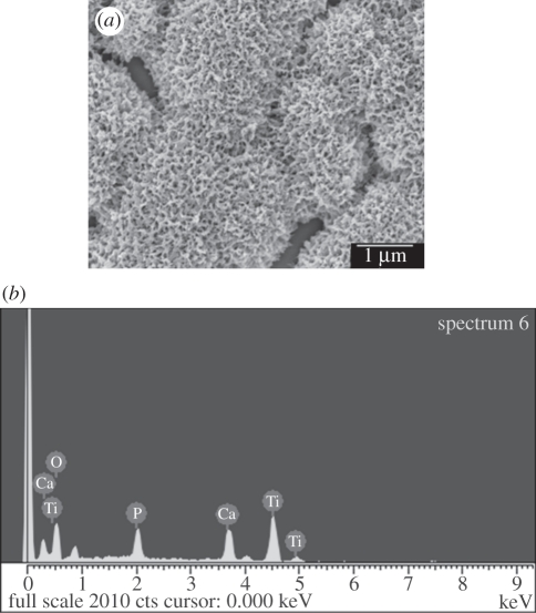
After a 1 day immersion in SBF, the morphology of nanoSiHA changed from rod-like particles to porous lamella-like crystals, and transformed to a spheroidal shape cauliflower-like structure, the typical feature of bone-like apatite formed in vitro, after 3 days (figure 9). EDX analysis (figure 9b) revealed that this newly formed structure was rich in Ca and P. The fast formation of surface apatite indicated the high bioactivity of the nanoSiHA deposited by TAEA.
Figure 9.
The changes of surface morphology of (a) nanoSiHA immersion in SBF. (b) EDX surface analysis shows the bone-like apatite formed after 3 days in SBF was rich in Ca and P.
3.4. In vitro culture with HOB cells
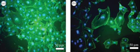
HOB cells were able to attach and grow on various nanoSiHA-patterned surfaces. Immunohistochemical staining of nuclei and actin cytoskeleton indicated preferential attachment of HOB cells on patterned surfaces as opposed to non-patterned surface (figure 10); HOB cells were more randomly assigned to the surface when a pattern was not present on the substrate.
Figure 10.
Confocal micrographs of HOB cells (nuclei, blue; actin, green) on (a) non-patterned and (b) pillar-patterned surface.
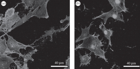
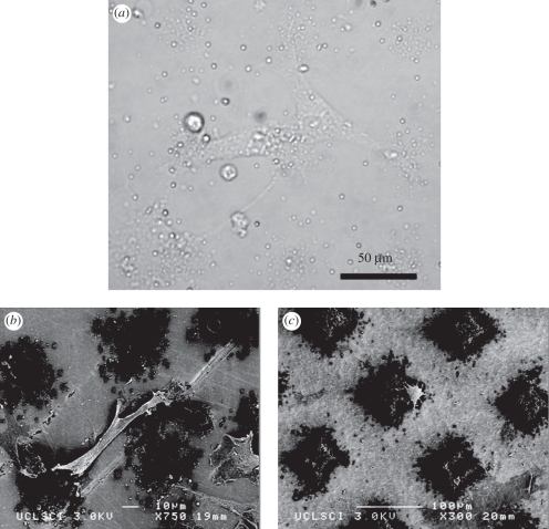
The pillar pattern appeared to support the cells as they can be seen directly on the apex of the structure, and HOB cells were aligned along the tracks and linked between track rows (figure 11). The filopodium is the organelle of a cell responsible for sensing the local topography. Long filopodia were found to be in contact with nanoSiHA patterns (figure 12a), and the linkage was related to the distance between the tracks and patterns. Distances between the track patterns ranged from 60 to 100 µm (table 2). HOB cells aligned along the track and between the tracks. Particularly, HOB cells appeared to stretch themselves according to the distance between the patterns. The length of the HOB cells increased from 80 to 115 µm when the gap between the tracks increased from 60 to 100 µm. This is different to the HOB cells response to the pillar patterns (table 3), where HOB cells stretched from one pillar to another when the gap was within 30 µm (figure 12b), while HOB cells attached to one pillar when the gap was over 50 µm (figure 12c). The effects of surface topography on HOB cell proliferation and differentiation are currently under systematic investigation.
Figure 11.
Confocal micrographs of the actin cytoskeleton of HOB cells on (a) tracks (b) pillar patterns.
Figure 12.
(a) Optical microscopy image of HOB cells (live) on nanoSiHA pillar pattern; (b) and (c) SEM micrographs of HOB cells attachment on nanoSiHA pillar with small (b) and large (c) gap.
Table 2.
Relationship between the length of HOB cell and the dimension of pillar (width and gaps).
| pillar width (µm) | gaps between pillars (µm) | length of HOB cell (µm) |
|---|---|---|
| 25 | 50 | 80 ± 10 |
| 45 | 60 | 75 ± 10 |
| 50 | 75 | 85 ± 12 |
Table 3.
Relationship between the length of HOB cell and the dimension of track (width and gaps).
| track width (µm) | gaps between tracks (µm) | length of HOB (µm) |
|---|---|---|
| 10 ± 2 | 60 ± 4 | 80 ± 9 |
| 15 ± 2 | 100 ± 3 | 110 ± 10 |
| 25 ± 4 | 100 ± 5 | 115 ± 11 |
It has been well recognized that topography has a profound effect on cellular adhesion, positioning and further proliferation and differentiation. The morphological response mechanism arises from the creation of anisotropic stresses. However, the origin and specific role of these stresses are debatable, and the underlying mechanism for topographical interaction with cells has yet to be elucidated. The difficulty lies in the infinite number of combinations of cell types, biomaterial compositions and topographical arrangements. Pierres et al. [25] reported that actin polymerization in the cytoskeleton rearrangement is vital for cell attachment. These polymerizations also act as a driving force for directional migration and morphological shifts. Filopodia are highly motile organelles involved in cellular processes of migration and sensing local topography. It has been shown that filopodia were less formed when the ridge-groove pattern topography was perpendicular, these may be owing to unfavourable stress, whereas parallel to the pattern, filopodia are more frequently formed. This, in turn, leads to the rearrangement of cellular cytoskeleton and polarization of the cell body and ultimately to the morphological effect of alignment and elongation. This view is supported by our study where the alignment and stretch of HOB cells were found on track patterns of nanoSiHA.
4. Conclusions
Nano-sized silicon-doped HA has been synthesized and subjected to TAEA patterning. The applied voltage, flow rate, spray time and distance between nozzle and substrate have been found to influence the formation of nanoSiHA patterns. The resolutions of nanoSiHA patterns can be improved by reducing the flow rate, varying the nozzle to substrate distance and spraying time. The surface of titanium substrate has been patterned with pillars and tracks of varying widths, line lengths and distances under the optimized TAEA-processing conditions. A fast bone-like apatite formation rate was found on nanoSiHA after immersion in SBF, thus demonstrating its high in vitro bioactivity. In vitro culture showed that HOB cells responded to patterned nanoSiHA, the length of HOB cells was found to be proportional to the gaps between the track patterns, but the relationship was not observed on the pillar patterns. The study has thus paved the way for future design of next generation implant surfaces to control and guide cellular responses.
Acknowledgements
Financial support from The Furlong Research Charitable Foundation is gratefully acknowledged.
References
- 1.De Groot K., Geesink R., Klein T., Serekian P. 1987. Plasma sprayed coatings of hydroxylapatite. J. Biomed. Mater. Sci. 21, 1375–1381 10.1002/jbm.820211203 (doi:10.1002/jbm.820211203) [DOI] [PubMed] [Google Scholar]
- 2.Hing K., Revell P., Smith N., Buckland T. 2006. Effect of silicon level on rate, quality and progression of bone healing within silicate substituted porous hydroxyapatite scaffolds. Biomaterials 27, 5014–5026 10.1016/j.biomaterials.2006.05.039 (doi:10.1016/j.biomaterials.2006.05.039) [DOI] [PubMed] [Google Scholar]
- 3.Patel N., Best S. M., Bonfield W., Gibson I. R., Hing K. A., Damien E., Revell P. A. 2002. A Comparative study on the in vivo behavior of hydroxyapatite and silicon substituted hydroxyapatite granules. J. Mater. Sci. Mater. Med. 13, 1199–1206 10.1023/A:1021114710076 (doi:10.1023/A:1021114710076) [DOI] [PubMed] [Google Scholar]
- 4.Carlisle E. M. 1972. Silicon: an essential element for the chick. Science 178, 619–621 10.1126/science.178.4061.619 (doi:10.1126/science.178.4061.619) [DOI] [PubMed] [Google Scholar]
- 5.Vallet-Regi M., Gonzalez-Calbet J. M. 2004. Calcium phosphates as substitution of bone tissues. Prog. Solid State Chem. 32, 1–31 10.1016/j.progsolidstchem.2004.07.001 (doi:10.1016/j.progsolidstchem.2004.07.001) [DOI] [Google Scholar]
- 6.Porter A. E., Patel N., Skepper J. N., Best S. M., Bonfield W. 2003. Comparison of in vivo dissolution processes in hydroxyapatite and silicon-substituted hydroxyapatite. Bioceramics 24, 4609–4620 10.1016/S0142-9612(03)00355-7 (doi:10.1016/S0142-9612(03)00355-7) [DOI] [PubMed] [Google Scholar]
- 7.Seaborn C. D., Nielsen F. H. 2002. Silicon deprivation decreases collagen formation in wounds and bone, and ornithine transaminase enzyme activity in liver. Bio. Trace Elem. Res. 89, 251–261 10.1385/BTER:89:3:251 (doi:10.1385/BTER:89:3:251) [DOI] [PubMed] [Google Scholar]
- 8.Reffitt D. M., Ogston N., Jugdaohsingh R., Cheung H. F. J. 2003. Orthosilicic acid stimulates collagen type 1 synthesis and osteoblastic differentiation in human osteoblast-like cells in vitro. Bone 32, 127–135 10.1016/S8756-3282(02)00950-X (doi:10.1016/S8756-3282(02)00950-X) [DOI] [PubMed] [Google Scholar]
- 9.Hahn B. D., Lee J. M., Park D. S., Choi J. J., Ryu J., Yoon W. H., Lee B. K., Shin D. S., Kim H. E. 2010. Aerosol deposition of silicon-substituted hydroxyapatite coatings for biomedical applications. Thin Solid Films 518, 2194–2199 10.1016/j.tsf.2009.09.024 (doi:10.1016/j.tsf.2009.09.024) [DOI] [Google Scholar]
- 10.Porter A. E., Rea S. M., Galtrey M., Best S. M., Barber Z. H. 2004. Production of thin film silicon-doped hydroxyapatite via sputter deposition. J. Mater. Sci. 39, 1895–1989 10.1023/B:JMSC.0000016213.77001.71 (doi:10.1023/B:JMSC.0000016213.77001.71) [DOI] [Google Scholar]
- 11.Thian E. S., Huang J., Best S. M., Barber Z. H., Bonfield W. 2005. Magnetron co-sputtered silicon-containing hydroxyapatite thin films—an in vitro study. Biomaterials 26, 2947–2956 10.1016/j.biomaterials.2004.07.058 (doi:10.1016/j.biomaterials.2004.07.058) [DOI] [PubMed] [Google Scholar]
- 12.Curtis A., Wilkinson C. 1997. Topographical control of cells. Biomaterials 18, 1573–1583 10.1016/S0142-9612(97)00144-0 (doi:10.1016/S0142-9612(97)00144-0) [DOI] [PubMed] [Google Scholar]
- 13.McDevitt T. C., Woodhouse K. A., Hauschka S. D., Murry C. E., Stayton P. S. 2003. Spatially organized layers of cardiomyocytes on biodegradable polyurethane films for myocardial repair. J. Biomed. Res. A 66, 586–595 (doi:10.1002/1097-4636(20010915)56:4<494) [DOI] [PubMed] [Google Scholar]
- 14.Roth E. A., Xu T., Das M., Gregory C., Hickman J. J., Boland T. 2004. Inkjet printing for high-throughput cell patterning. Biomaterial 25, 3707–3715 10.1016/j.biomaterials.2003.10.052 (doi:10.1016/j.biomaterials.2003.10.052) [DOI] [PubMed] [Google Scholar]
- 15.Perizzolo D., Lacefield W. R., Brunette D. M. 2001. Interaction between topography and coating in the formation of bone nodules in culture for hydroxyapatite- and titanium-coated micromachined surfaces. J. Biomed. Mater. Res. 56, 494–503 (doi:10.1002/1097-4636(20010915)56:4<494::AID-JBM1121>3.0.CO;2-X) [DOI] [PubMed] [Google Scholar]
- 16.Price R. L., Ellison K., Haberstroh K. M., Webster T. J. 2004. Nanometer surface roughness increases select osteoblast adhesion on carbon nanofiber compacts. J. Biomed. Mater. Res. A 70, 129–138 10.1002/jbm.a.30073 (doi:10.1002/jbm.a.30073) [DOI] [PubMed] [Google Scholar]
- 17.Wang J. H. C., Grood E. S., Florer J., Wenstrup R. 2000. Alignment and proliferation of MC3T3-E1 osteoblasts in microgrooved silicone substrata subjected to cyclic stretching. J. Biomech. 33, 729–735 10.1016/S0021-9290(00)00013-0 (doi:10.1016/S0021-9290(00)00013-0) [DOI] [PubMed] [Google Scholar]
- 18.Gallagher J. O., McGhee K. F., Wilkinson C. D. W., Riehle M. O. 2002. Interaction of animal cells with ordered nanotopography. IEEE Trans. Nanobiosci. 1, 24–28 10.1109/TNB.2002.806918 (doi:10.1109/TNB.2002.806918) [DOI] [PubMed] [Google Scholar]
- 19.Li X., Huang J., Edirisinghe M. J. 2008. Novel patterning of nano-bioceramics: template-assisted electrohydrodynamic atomization spraying. J. R. Soc. Interface 5, 253–257 10.1098/rsif.2007.1162 (doi:10.1098/rsif.2007.1162) [DOI] [PMC free article] [PubMed] [Google Scholar]
- 20.Li X. A., Koller G., Huang J., Di Silvio L., Renton T., Esat M., Bonfield W., Edirisinghe M. 2010. Novel jet-based nano-hydroxyapatite patterning technique for osteoblast guidance. J. R. Soc. Interface 7, 189–197 10.1098/rsif.2009.0101 (doi:10.1098/rsif.2009.0101) [DOI] [PMC free article] [PubMed] [Google Scholar]
- 21.Li X., Huang J., Edirisinghe M. 2008. Development of nano-hydroxyapatite coating by electrohydrodynamic atomization spraying. J. Mater. Sci. Mater. Med. 19, 1545–1551 10.1007/s10856-007-3303-3 (doi:10.1007/s10856-007-3303-3) [DOI] [PubMed] [Google Scholar]
- 22.Jaworek A., Krupa A. 1999. Classification of the modes of EHD spraying. J. Aerosol Sci. 30, 873–893 10.1016/S0021-8502(98)00787-3 (doi:10.1016/S0021-8502(98)00787-3) [DOI] [Google Scholar]
- 23.Kokubo T., Kushitani H., Sakka S., Kitsugi T., Yamamuro T. 1990. Solutions able to reproduce in vivo surface-structure change in bioactive glass ceramic A-W. J. Biomed. Mater. Res. 24, 721–734 10.1002/jbm.820240607 (doi:10.1002/jbm.820240607) [DOI] [PubMed] [Google Scholar]
- 24.Di Silvio L., Gurav N. 2001. Osteoblasts. Human cell culture: primary mesenchymal cells, vol. ix, pp. 241 London, UK: Kluwer Academic Publishers [Google Scholar]
- 25.Pierres A., Benoliel A. M., Touchard D., Bongrand P. 2008. How cells tiptoe on adhesive surfaces before sticking. Biophys. J. 94, 4114–4122 10.1529/biophysj.107.125278 (doi:10.1529/biophysj.107.125278) [DOI] [PMC free article] [PubMed] [Google Scholar]


