Abstract
Mineralized collagen fibrils (MCFs) are distinct building blocks for bone material and perform an important mechanical function. A novel experimental technique using combined atomic force microscopy and scanning electron microscopy is used to manipulate and measure the mechanical properties of individual MCFs from antler, which is a representative bone tissue. The recorded stress–strain response of individual MCFs under tension shows an initial linear deformation region for all fibrils, followed by inhomogeneous deformation above a critical strain. This inhomogeneous deformation is indicative of fibrils exhibiting either yield or strain hardening and suggests possible mineral compositional changes within each fibril. A phenomenological model is used to describe the fibril nano-mechanical behaviour.
Keywords: biomechanics, bone, atomic force microscopy, mineralized collagen fibril
1. Introduction
The origin of the outstanding mechanical properties of bone is contentious, with structural organization over different length scales and constituent properties all expected to contribute [1–3]. Separating these potentially synergistic effects is critical in understanding the mechanism for bone deformation and fracture, but is often hindered by the difficulty in testing components that have dimensions approaching the nanoscale. Collagen fibrils (CFs) are one such constituent that act as an organic framework in all bone material and are thus expected to play a significant role in determining the mechanical response of bone. A diversity of CF assemblies exist in bone materials, with the antlers of deer [1,4,5] notable as one of the toughest natural materials. Bone is structurally a composite as nano-fibres of CFs act as a template for the mineralization of carbonated apatite crystals. Importantly, many of these apatite minerals are intra-fibrillar in antler and provide a model composite fibre system of collagen reinforced with mineral, as opposed to many other bones where the mineral is also found in extra-fibrillar spaces [4–7]. Despite this structural information, the mechanical properties of these mineralized collagen fibrils (MCFs) and their influence on the overall bone mechanics, such as toughness in antler, have yet to be determined.
In this paper, we perform tensile testing on individual MCFs from antler using a combination of atomic force microscopy (AFM) to manipulate and mechanically test individual MCFs and scanning electron microscopy (SEM) to provide high-resolution in situ imaging. The combined AFM–SEM technique allows direct mechanical testing of MCFs from bulk bone specimens, which has yet to be obtainable using current methodology [8–10]. Specifically, previous work has examined the mechanical properties of unmineralized CFs from a number of sources directly using AFM [9,10]. AFM is often preferred to other techniques as both high-resolution imaging and mechanical deformation can be provided using a single AFM probe. First attempts on direct mechanical testing of in vitro-assembled human type I CFs were carried out by Graham et al. [11] using an AFM probe to pull an individual CF from a connecting substrate. However, the relatively low CF elastic modulus (32 MPa) suggested sliding of the CF from the AFM probe during testing, which was overcome using glue at the fibril–AFM probe junction to give modulus values approaching 0.8 GPa [10]. Further research was carried out on the mechanical properties of unmineralized individual CFs from sea cucumber using a microelectromechanical systems (MEMS) device [9]. The selection from this source was beneficial as the fibril diameters are typically relatively large, allowing manipulation of fibrils under optical microscopy for nano-mechanical tests. However, both AFM and MEMS devices are limited as individual fibrils are required to be first removed from the parent material sample, typically using chemical treatments that will dissolve hydroxyapatite in mineralized fibrillar assemblies. Other methods have overcome this limitation by using combinations of synchrotron X-ray diffraction together with tensile testing [7,12,13] and nano-indentation [14] to deform bulk bone materials and derive CF and mineral mechanics. While powerful, these techniques average the mechanical properties of the constituents over the volume of interest, typically many tens of cubic micrometres in the case of X-ray diffraction. Therefore, the mechanical properties of MCF constituents as well as their influence on bone deformation and fracture are still to be ascertained.
2. Experiment
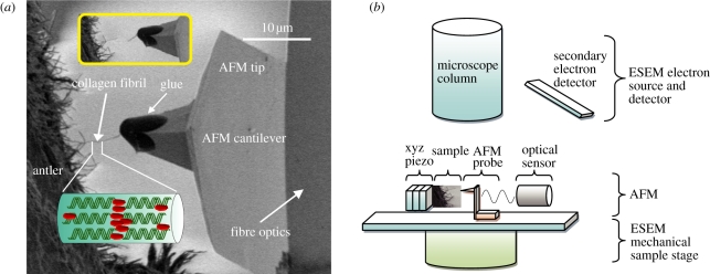
The prevalence of mineral within the collagen fibrillar framework in antler makes this material an ideal source of model MCFs. Specifically, most of the mineral in antler is found within the fibril, resulting in a simple composite fibre of mineral-reinforcing collagen molecules as shown in figure 1a. Antler is notable as a bone material that exists outside the body, and the cortical bone tissue in antler is known to have low water content varying from 13.2 ± 1.2 to 22.2 ± 4.8% depending on different times of the year [15]. This relatively dry state of the antler is more compatible with the environment of an electron microscope chamber.
Figure 1.
(a) SEM image showing a typical testing configuration. A large number of exposed CFs observed at the fracture surface of antler bone. An individual CF protruding from the fracture surface is attached to the glue at the end of the AFM probe. Translation of the AFM probe away from the fibril causes tensile deformation of the fibril until failure occurs, which is shown in the inset image. (b) Schematic showing set-up of combined SEM–AFM. (Online version in colour.)
Samples were extracted from the main beam from the antler (after removal of velvet) of a mature red deer (Cervus elaphus). Because recent studies have shown that the selection of tissue region within the antler beam affects the composition and mechanical properties [7,15], the samples were selected from the same compact cortical shell near the antler–pedicle junction. Small beams of antler with dimensions of 3 × 20 × 0.2 mm were cut from the bulk material by using a water-cooled rotating diamond saw (Struers Accatom-5). The long direction of samples was oriented parallel to the antler main beam direction, which is also the principal osteonal axis. The beams were transferred into Hank's balanced solution and left overnight. This procedure allows full sample rehydration and mitigates mineral loss that may occur in distilled water or physiological saline. Samples were fractured perpendicular to the long axis to expose a number of individual fibrils at the fracture surface. Water on the surface of the sample was removed by filter paper to avoid interference with SEM imaging.
Nano-mechanical testing of individual MCFs was performed using a custom-built AFM (Attocube GmbH, Germany) fitted within the chamber of an SEM (Quanta 3D Environmental SEM, FEI Company, EU/USA). The combination of both SEM and AFM is powerful as the AFM provides high-resolution force information while the SEM gives imaging capabilities. The applications of AFM–SEM combination on testing fibrous samples at the nanoscale have been recorded previously [16,17]. A schematic of the combined AFM–SEM set-up is shown in figure 1b and highlights how the AFM probe is perpendicular to the fracture plane of the antler and along the principal axis of the exposed CFs. Clamping of an individual CF to the end of the AFM probe was achieved by first translating the end of the AFM probe into a droplet of glue (Poxipol, Argentina) contained within the SEM chamber. Removal of the AFM probe from the glue deposited a small amount of glue at the apex of the AFM probe. The AFM probe was subsequently moved towards the free end of the exposed CF until contact between the fibril and the glue at the AFM probe apex was achieved as shown in figure 1a. This contact was achieved consistently within a 3–5 min timeframe from the fixing of glue within the SEM chamber. Manipulation and attachment of the CF to the AFM probe was observed using the electron beam of the SEM at long working distance (15 mm) and low accelerating voltage (2 kV) to ensure that no electron beam damage occurs, as has been shown for soft polymer systems [17]. Solidification of the glue occurred approximately 10 min after contacting with the fibril free end. We note that the manipulation of CFs requires SEM imaging as opposed to AFM imaging. AFM imaging is suitable for examining bone specimens where the CFs are in the plane of the fracture surface [18,19] but is unable to image surfaces where the CFs are perpendicular to the fracture surface because of the instability of this surface to the imaging AFM probe.
Fibrils attached to the AFM probe were used for subsequent tensile testing by translation of the AFM probe away from the fracture surface. This translation caused a corresponding bending of the AFM cantilever until failure of the individual CF as shown in figure 1a, inset. The force applied to the CF was calculated from the spring constant of the AFM cantilever, found using the thermal noise method [20] and measuring the cantilever deflection using an optical interferometer set-up (Attocube Systems, Germany) situated behind the cantilever. The calculation of the stress in the CF requires the accurate determination of the fibril diameter. The diameter of MCFs was measured by pixel analysis in the SEM images captured before mechanical testing using ImageJ (NIH, USA). The diameters of CFs mechanically tested in this work have a mean value of 92.4 ± 12 nm. All mechanical testing ensured that the CF axis is in the same plane as the SEM image, otherwise force applied to the fibril will cause fibril orientation as opposed to deformation. This configuration was achieved by moving the AFM probe attached to the CF above and below the SEM plane of view. A small force will be recorded during this out of plane movement if the fibril axis is aligned with the plane. Thus, only fibrils with their principal axis in the SEM view plane are tested. All fibrils tested failed in the middle of their free length, away from the holding glue and the bone surface.
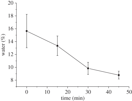
X-ray energy dispersive spectroscopy (EDS) microanalysis within an SEM (Inspect SEM, FEI Company, EU/USA) was used to investigate the composition of antler samples used in experiments and verify whether the regions containing the mechanically tested CFs are mineralized. Chemical composition (Ca/P) ratio has been previously used as a marker in EDS for the calculation of the mineral distribution in bone tissues [21–23] and is thus employed in our study. Twenty EDS spectra within an area of 100 × 100 µm2 were collected at the tested fracture surface of antler in order to determine the calcium content. Finally, water loss from the MCF sample owing to exposure to the SEM vacuum chamber during the test was found to be minimal from thermal gravimetric analysis (TGA). The TGA test showed 13.35 ± 1.52% water content remained in the specimens exposed to vacuum for 15 min, which is comparable to the fresh antler bone [15] (see electronic supplementary material for further details; figure 2). The manipulation and mechanical testing of the MCFs were accomplished in vacuum over a 10–12 min experimental period, indicating that the samples were still hydrated. This low water loss owing to the short time of exposure in vacuum has also been observed in synthetic nano-fibres swollen with water [17]. In addition, during the mineralization process of CFs, the water in the gap regions of the fibril is replaced by the mineral phase, which makes MCFs less hydrated compared with CFs [24].
Figure 2.
Water content in samples varies with different exposure time to the vacuum conditions of the SEM instrument. The water content was measured as weight lost during the TGA tests when heating the samples up to 200°C.
3. Results
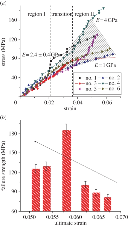
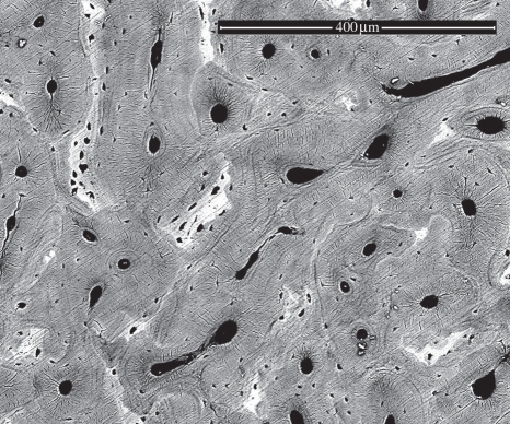
The stress–strain behaviour of six individual MCFs was measured using the AFM–SEM with the results shown in figure 3. All fibrils show a linear stress–strain response during initial tensile loading up to strains of between 2 and 3.7 per cent. This strain value at the limit of the linear response corroborates previous deformation of hydrated antler using X-ray studies [7], indicating that the collagen fibrils are also hydrated despite the vacuum environment of the SEM. The linear modulus in region I of the MCF stress–strain curve is highly reproducible with a value of 2.4 ± 0.4 GPa and is considerably larger than previous collagen moduli [9,10], indicating that the fibrils have some degree of mineralization that improves their stiffness. Further tensile deformation of an MCF causes an observed transition to a mechanically inhomogeneous region II. Fibrils in region II exhibit either yield behaviour or strain hardening including higher modulus and ultimate strength, but a decrease in the fibril ultimate strain to failure. No fibril failure was observed in the SEM image during the tensile testing until catastrophic failure. The last data point in the stress–strain behaviour of the MCFs from figure 3 was recorded just before this catastrophic failure. The detailed mechanical properties of all six CFs are recorded in table 1. The antler bone mineral content at the fracture surface was evaluated using EDS and following previous works [21–23]. Preliminary SEM back-scattered images shown in figure 4 indicated regions of high and low mineralization at the fracture surface. The corresponding EDS analysis of elements present at the fracture surface, including O, Na, Mg, S, P and Ca, indicated that the calcium content varied considerably from 31.64 to 61.34 per cent. This calcium content shows that the bone is not only mineralized but there is a large variation in the mineral content.
Figure 3.
(a) The stress–strain plot individual MCFs. All MCFs show a linear stress–strain behaviour with a modulus of 2.4 ± 0.4 GPa in region I, before the transition point. Beyond the transition in region II, MCFs exhibit inhomogeneous stress–strain deformation behaviour as indicated by the shaded area. Inhomogeneous deformation of MCFs is through either a lowering of the modulus indicating yield or an enhancement of the modulus. (b) Failure strength versus ultimate strain to failure of MCFs in tension. The arrow indicates ‘brittle-like’ behaviour of increasing MCF strength with decreasing failure strain. (Online version in colour.)
Table 1.
Mechanical properties of six MCFs tested.
| test no. | diameter (nm) | modulus I (GPa) | modulus II (GPa) | ɛUTS (%) | σUTS (MPa) |
|---|---|---|---|---|---|
| 1 | 72.9 | 2.30 | 1.95 | 5.14 | 125.68 |
| 2 | 102.5 | 2.29 | 0.96 | 6.46 | 89.05 |
| 3 | 90.7 | 1.91 | 0.98 | 6.72 | 82.22 |
| 4 | 96.0 | 3.03 | 3.85 | 5.81 | 185.00 |
| 5 | 86.0 | 2.30 | 2.78 | 5.37 | 129.50 |
| 6 | 106.0 | 2.46 | 1.18 | 6.23 | 100.66 |
| mean ± s.d. | 92.4 ± 12.0 | 2.38 ± 0.37 | 1.95 ± 1.17 | 5.96 ± 0.62 | 118.68 ± 37.67 |
Figure 4.
SEM back-scattered image of the antler bone fracture surface. The light regions on the image indicate higher mineralization. The corresponding Ca/P ratio in the image varied from 1.48 to 3.12, indicating hydroxyapatite mineral is present [22,23], and the content varies throughout the antler bone.
4. Discussion
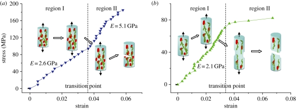
The deformation behaviour of individual CFs in tension described by regions I and II is indicative of structural or compositional variation within the fibrils themselves. A mechanistic description of the deformation of individual MCFs can be made by comparing our experimental results in this work with molecular dynamics simulations [25]. These simulations show some similarity with our individual MCF tensile tests, with an initial linear response followed by heterogeneous deformation in the MCF stress–strain behaviour. The initial linear behaviour was mostly from the elastic behaviour of the MCF constituents, and the tensile modulus calculated from region I was dependent on the amount of mineral contained within the fibril. The presence of the mineral phase increases the local yield regions in MCFs when tensile load is applied, which suggests the MCFs fail locally to ensure that the majority of the fibril length remains undamaged after exposure of the fibrils during sample preparation [25]. The linear stress–strain fibril response of the MCFs in figure 3 after primary mechanical tests provided an experimental validation of this mechanism as testing of fibrils after yield will give a nonlinear response. The heterogeneous deformation zone, defined by region II in this work, was shown in the molecular simulation to be also due to the amount of mineral in the CFs. The MCFs in the simulation work displayed a characteristic stress–strain curve similar to that in figure 5b, indicating that deformation in region II is due to intermolecular slippage and failure at the mineral–tropocollagen macromolecule interface. We note that other simulations show how intermolecular slippage in non-MCFs is suppressed when cross-link density is increased [8]. However, the MCF behaviour, as shown in figure 5a, indicates a lack of slippage as the stiffness of the fibril increases with increasing strain. The variation in mineral content from EDS investigations suggests that some CFs may be more mineralized than others. Table 1 supports this assumption, with MCFs having a higher tensile modulus in region I also exhibiting an increased tensile modulus in region II. The increased tensile modulus in region II relative to region I cannot be simply due to mineral content and must be due to stiffening of the fibril with strain. Classical work on tendon, essentially an aligned unmineralized CF array, shows how crimping of tropocollagen molecules is removed with increasing strain, resulting in an increased tensile modulus. The increased tensile modulus in MCFs as shown in figure 5a may therefore be due to the removal of crimping in the MCF. In addition, molecular dynamics simulations do not show this behaviour as the model assumes an uncrimped, uniaxially aligned tropocollagen network. The nano-mechanics of tropocollagen–hydroxyapatite (TC–HAP) systems are strongly dependent on mineral content, but the changes in hydroxyapatite crystal shape [26] as well as their texture and orientation [27] are also considered to have an influence on the mechanical behaviour of individual MCFs. A previous study has shown that the CF morphology [28] and TC molecule length [29] are critical in determining the tensile strength. In addition, the cross-link density of TC networks in single CFs is also believed to play a role in defining the mechanical properties of CFs [8]. A recent atomistic simulation study on osteogenesis imperfecta-affected bone has indicated that the effect of TC mutations on the strength of the TC–HAP system is insignificant [30], in contrast to previous work [31]. Instead, the mineral distribution has a crucial impact on the overall strength of TC–HAP biomaterials.
Figure 5.
Tensile stress–strain curves for MCFs showing two distinct mechanical behaviours. Tropocollagen uncoiling occurs initially in both types of fibrils within region I. In (a), the fibril shows an enhanced elastic modulus in region II owing to mineral increasing the stress transfer between tropocollagen macromolecules. In (b), the low mineral density within the fibrils allows sliding between tropocollagen molecules, resulting in a plastic deformation. (Online version in colour.)
The implications of nano-mechanical heterogeneity have been more widely studied and previous work has illustrated how heterogeneous deformation in mineralized tissue aids energy dissipation [14,32,33]. The principal mechanical function of antler is energy absorption during impact, and therefore promotion of heterogeneous deformation is favourable. Thus, our work highlights how heterogeneous deformation originates from the nano-mechanical behaviour of the MCFs themselves.
In conclusion, the stress–strain behaviour of individual MCFs from antler was measured using combination AFM–SEM. An initial region of homogeneous fibrillar deformation was succeeded by inhomogeneous mechanical behaviour above applied strains of 2–3.7%. A molecular mechanism is proposed to explain these different fibril mechanical responses to external load. The nano-mechanical testing technique developed in this work may also be applicable to the measurement of bone at different mineralization and diseased states.
References
- 1.Currey J. D. 1999. The design of mineralised hard tissues for their mechanical functions. J. Exp. Biol. 202, 3285–3294 [DOI] [PubMed] [Google Scholar]
- 2.Rho J. Y., Kuhn-Spearing L., Zioupos P. 1998. Mechanical properties and the hierarchical structure of bone. Med. Eng. Phys. 20, 92–102 10.1016/S1350-4533(98)00007-1 (doi:10.1016/S1350-4533(98)00007-1) [DOI] [PubMed] [Google Scholar]
- 3.Weiner S., Traub W., Wagner H. D. 1999. Lamellar bone: structure–function relations. J. Struct. Biol. 126, 241–255 10.1006/jsbi.1999.4107 (doi:10.1006/jsbi.1999.4107) [DOI] [PubMed] [Google Scholar]
- 4.Rajaram A., Ramanathan N. 1982. Tensile properties of antler bone. Calcif. Tissue Int. 34, 301–305 10.1007/BF02411255 (doi:10.1007/BF02411255) [DOI] [PubMed] [Google Scholar]
- 5.Zioupos P., Currey J. D., Sedman A. J. 1994. An examination of the micromechanics of failure of bone and antler by acoustic emission tests and laser scanning confocal microscopy. Med. Eng. Phys. 16, 203–212 10.1016/1350-4533(94)90039-6 (doi:10.1016/1350-4533(94)90039-6) [DOI] [PubMed] [Google Scholar]
- 6.Chen P. Y., Stokes A. G., McKittrick J. 2009. Comparison of the structure and mechanical properties of bovine femur bone and antler of the North American elk (Cervus elaphus canadensis). Acta Biomater. 5, 693–706 10.1016/j.actbio.2008.09.011 (doi:10.1016/j.actbio.2008.09.011) [DOI] [PubMed] [Google Scholar]
- 7.Krauss S., Fratzl P., Seto J., Currey J. D., Estevez J. A., Funari S. S., Gupta H. S. 2009. Inhomogeneous fibril stretching in antler starts after macroscopic yielding: indication for a nanoscale toughening mechanism. Bone 44, 1105–1110 10.1016/j.bone.2009.02.009 (doi:10.1016/j.bone.2009.02.009) [DOI] [PubMed] [Google Scholar]
- 8.Buehler M. J. 2008. Nanomechanics of collagen fibrils under varying cross-link densities: atomistic and continuum studies. J. Mech. Behav. Biomed. Mater. 1, 59–67 10.1016/j.jmbbm.2007.04.001 (doi:10.1016/j.jmbbm.2007.04.001) [DOI] [PubMed] [Google Scholar]
- 9.Shen Z. L., Dodge M. R., Kahn H., Ballarini R., Eppell S. J. 2008. Stress–strain experiments on individual collagen fibrils. Biophys. J. 95, 3956–3963 10.1529/biophysj.107.124602 (doi:10.1529/biophysj.107.124602) [DOI] [PMC free article] [PubMed] [Google Scholar]
- 10.Rijt J. A. J., van der Rijt J. A. J., van der Werf K. O., Bennink M. L., Dijkstra P. J., Feijen J. 2006. Micromechanical testing of individual collagen fibrils. Macromol. Biosci. 6, 697–702 10.1002/mabi.200600063 (doi:10.1002/mabi.200600063) [DOI] [PubMed] [Google Scholar]
- 11.Graham J. S., Vomund A. N., Phillips C. L., Grandbois M. 2004. Structural changes in human type I collagen fibrils investigated by force spectroscopy. Exp. Cell Res. 299, 335–342 10.1016/j.yexcr.2004.05.022 (doi:10.1016/j.yexcr.2004.05.022) [DOI] [PubMed] [Google Scholar]
- 12.Gupta H. S., Zioupos P. 2008. Fracture of bone tissue: the ‘hows' and the ‘whys'. Med. Eng. Phys. 30, 1209–1226 10.1016/j.medengphy.2008.09.007 (doi:10.1016/j.medengphy.2008.09.007) [DOI] [PubMed] [Google Scholar]
- 13.Gupta H. S., Wagermaier W., Zickler G. A., Aroush D. R. B., Funari S. S., Roschger P., Wagner H. D., Fratzl P. 2005. Nanoscale deformation mechanisms in bone. Nano Lett. 5, 2108–2111 10.1021/nl051584b (doi:10.1021/nl051584b) [DOI] [PubMed] [Google Scholar]
- 14.Tai K., Dao M., Suresh S., Palazoglu A., Ortiz C. 2007. Nanoscale heterogeneity promotes energy dissipation in bone. Nat. Mater. 6, 454–462 10.1038/nmat1911 (doi:10.1038/nmat1911) [DOI] [PubMed] [Google Scholar]
- 15.Currey J. D., Landete-Castillejos T., Estevez J., Ceacero F., Olguin A., Garcia A., Gallego L. 2009. The mechanical properties of red deer antler bone when used in fighting. J. Exp. Biol. 212, 3985–3993 10.1242/jeb.032292 (doi:10.1242/jeb.032292) [DOI] [PubMed] [Google Scholar]
- 16.Hang F., Lu D., Barber A. H. 2009. Combined AFM–SEM for mechanical testing of fibrous biological materials. In Structure-property relationships in biomineralized and biomimetic composites (eds Kisailus D., Estroff L., Gupta H. S., Landis W. J., Zavattieri P. D.), pp. 135–140 Warrendale, PA: Materials Research Society [Google Scholar]
- 17.Hang F., Lu D., Li S. W., Barber A. H. 2009. Stress–strain behavior of individual electrospun polymer fibers using combination AFM and SEM. In Probing mechanics at nanoscale dimensions (eds Tamura N., Minor A., Friedman C. L.), pp. 87–91 Warrendale, PA: Materials Research Society [Google Scholar]
- 18.Hassenkam T., Fantner G. E., Cutroni J. A., Weaver J. C., Morse D. E., Hansma P. K. 2004. High-resolution AFM imaging of intact and fractured trabecular bone. Bone 35, 4–10 10.1016/j.bone.2004.02.024 (doi:10.1016/j.bone.2004.02.024) [DOI] [PubMed] [Google Scholar]
- 19.Tai K., Ortiz C. 2006. Nanomechanical heterogeneity of bone at the length scale of individual collagen fibrils. Abstr. Pap. Am. Chem. Soc. 231, 179-PMSE [Google Scholar]
- 20.Sader J. E., Larson I., Mulvaney P., White L. R. 1995. Method for the calibration of atomic-force microscope cantilevers. Rev. Sci. Instrum. 66, 3789–3798 10.1063/1.1145439 (doi:10.1063/1.1145439) [DOI] [Google Scholar]
- 21.Boyde A. 1998. Bone and BSE. Vet. Rec. 142, 288–288 [PubMed] [Google Scholar]
- 22.Eidelman N., Boyde A., Bushby A. J., Howell P. G. T., Sun J. R., Newbury D. E., Miller F. W., Robey P. G., Rider L. G. 2009. Microstructure and mineral composition of dystrophic calcification associated with the idiopathic inflammatory myopathies. Arthritis Res. Ther. 11, R159. 10.1186/ar2841 (doi:10.1186/ar2841) [DOI] [PMC free article] [PubMed] [Google Scholar]
- 23.Ferguson V. L., Bushby A. J., Boyde A. 2003. Nanomechanical properties and mineral concentration in articular calcified cartilage and subchondral bone. J. Anat. 203, 191–202 10.1046/j.1469-7580.2003.00193.x (doi:10.1046/j.1469-7580.2003.00193.x) [DOI] [PMC free article] [PubMed] [Google Scholar]
- 24.Lees S. 2003. Mineralization of type I collagen. Biophys. J. 85, 204–207 10.1016/S0006-3495(03)74466-X (doi:10.1016/S0006-3495(03)74466-X) [DOI] [PMC free article] [PubMed] [Google Scholar]
- 25.Buehler M. J. 2007. Molecular nanomechanics of nascent bone: fibrillar toughening by mineralization. Nanotechnology 18, 295102. 10.1088/0957-4484/18/29/295102 (doi:10.1088/0957-4484/18/29/295102) [DOI] [Google Scholar]
- 26.Dubey D. K., Tomar V. 2009. Role of the nanoscale interfacial arrangement in mechanical strength of tropocollagen–hydroxyapatite-based hard biomaterials. Acta Biomater. 5, 2704–2716 10.1016/j.actbio.2009.02.035 (doi:10.1016/j.actbio.2009.02.035) [DOI] [PubMed] [Google Scholar]
- 27.Dubey D. K., Tomar V. 2010. Tensile and compressive loading effects on texture dependent nanoscale mechanical behavior of model tropocollagen–hydroxyapatite biomaterials. J. Comput. Theor. Nanosci. 7, 1306–1316 10.1166/jctn.2010.1485 (doi:10.1166/jctn.2010.1485) [DOI] [Google Scholar]
- 28.Parkinson J., Brass A., Canova G., Brechet Y. 1997. The mechanical properties of simulated collagen fibrils. J. Biomech. 30, 549–554 10.1016/S0021-9290(96)00151-0 (doi:10.1016/S0021-9290(96)00151-0) [DOI] [PubMed] [Google Scholar]
- 29.Buehler M. J. 2006. Atomistic and continuum modeling of mechanical properties of collagen: elasticity, fracture, and self-assembly. J. Mater. Res. 21, 1947–1961 10.1557/jmr.2006.0236 (doi:10.1557/jmr.2006.0236) [DOI] [Google Scholar]
- 30.Dubey D. K., Tomar V. 2010. Effect of osteogenesis imperfecta mutations in tropocollagen molecule on strength of biomimetic tropocollagen–hydroxyapatite nanocomposites. Appl. Phys. Lett. 96, 023703. 10.1063/1.3279158 (doi:10.1063/1.3279158) [DOI] [Google Scholar]
- 31.Gautieri A., Vesentini S., Redaelli A., Buehler M. J. 2009. Single molecule effects of osteogenesis imperfecta mutations in tropocollagen protein domains. Protein Sci. 18, 161–168 10.1002/pro.21 (doi:10.1002/pro.21) [DOI] [PMC free article] [PubMed] [Google Scholar]
- 32.Fantner G. E., et al. 2005. Sacrificial bonds and hidden length dissipate energy as mineralized fibrils separate during bone fracture. Nat. Mater. 4, 612–616 10.1038/nmat1428 (doi:10.1038/nmat1428) [DOI] [PubMed] [Google Scholar]
- 33.Phelps J. B., Hubbard G. B., Wang X., Agrawal C. M. 2000. Microstructural heterogeneity and the fracture toughness of bone. J. Biomed. Mater. Res. 51, 735–741 (doi:10.1002/1097-4636(20000915)51:4<735::AID-JBM23>3.0.CO;2-G) [DOI] [PubMed] [Google Scholar]


