

Abstract
Coupled equations describing the radial and translational dynamics of an encapsulated gas bubble in an ultrasound field are derived by using the Lagrangian formalism. The equations generalize Church’s theory by allowing for the translation motion of the bubble and radiation losses due to the compressibility of the surrounding liquid. The expression given by Church for the inner bubble radius corresponding to the unstrained state of the bubble shell is also refined, assuming that the shell can be of arbitrary thickness and impermeable to gas. Comparative linear analysis of the radial equation is carried out relative to Church’s theory. It is shown that there are substantial departures from predictions of Church’s theory. The proposed model is applied to evaluate radiation forces exerted on encapsulated bubbles and their translational displacements. It is shown that in the range of relatively high frequencies encapsulated bubbles are able to translate more efficiently than free bubbles of the equivalent size.
I. INTRODUCTION
Interest in theoretical models describing the dynamics of encapsulated gas bubbles in an ultrasound field is motivated by increasingly growing use of contrast agents in ultrasound biomedical applications. Of special interest are models in the form of a Rayleigh-Plesset-type equation as they are more amenable to theoretical analysis, more convenient for numerical simulations, and can with comparative ease be applied to model the dynamics of more than one bubble. The first of such models was proposed by de Jong et al.1,2 They modified the Rayleigh-Plesset equation by phenomenologically introducing an additional restoring force due to the stiffness of the bubble shell and an additional damping due to internal friction inside the shell. The modified equation was used to model the radial oscillation of Albunex contrast agent. Subsequently, Frinking and de Jong3 proposed another version of this equation that was intended to model the radial dynamics of thick-shelled contrast agents such as Quantison and Myomap. It should be emphasized that both of the above-mentioned models are based on qualitative arguments rather than rigorous theoretical derivations.
A more sophisticated and theoretically justified model was developed by Church.4 He considered a spherical encapsulated gas bubble enclosed in an incompressible solid elastic shell and surrounded by an incompressible viscous Newtonian liquid. The viscous damping inside the shell was also taken into account. Using a consistent theoretical approach, Church derived a Rayleigh-Plesset-type equation describing the radial motion of the bubble. The only ad hoc assumption that he used concerns determination of the inner radius of the bubble shell corresponding to the unstrained state of the shell.
More recently, using a modified Herring equation5 along with some elements of Church’s theory, the behavior of a contrast agent bubble was modeled by Morgan et al.6 and Dayton et al.7 In the latter work, the radial equation was also supplemented with a translational equation to estimate the magnitude of radiation force on contrast agents and compare the theoretical results with experiments.
All the above-mentioned papers show that, as a matter of fact, any modification of the Rayleigh-Plesset equation, based on reasonable assumptions, can be fitted to provide good agreement with specific experiments. However, models that involve ad hoc parameters cannot guarantee reliable predictions for cases different from that to which they were fitted, even if distinctions are physically insignificant. This fact is well illustrated by Frinking and de Jong’s3 article, where an effective bulk modulus, Keff, is introduced to describe the elasticity of the encapsulating shell of contrast agents such as Quantison, Myomap, and Albunex. All of these agents consist of air bubbles encapsulated by a shell of human albumin. They differ only in diameter and the shell thickness. For Quantison, which has a mean diameter of 3.2 μm and the shell thickness of which is 200–300 nm and proportional to the bubble diameter, Frinking and de Jong obtained Keff=17.4 MPa. For Myomap, which has a mean diameter of 10 μm and the shell of which is approximately three times thicker than the Quantison shell, Keff =78.4 MPa. Measurements for Albunex filtered with 12-, 8-, 5-, and 3-μm pore size mechanical filters yielded the following values of Keff, respectively: 1.3, 2.0, 6.2, and 9.8 MPa. These results are believed to be explained by the fact that the thickness of the Albunex shell, which is about 15–20 nm, is independent of the bubble diameter, the latter being about 3.8 μm. It is evident that such a model is very inconvenient, especially if we are going to simulate the dynamics of a contrast agent cluster consisting of bubbles of different size. When a model is based on real physical parameters, distinctions in the behavior of the above-mentioned contrast agents should arise in a natural way, just varying sizes instead of fitting Keff to every new set of the bubble geometrical adjectives.
Models accounting for the translational motion of contrast agents deserve special notice. They have not received proper consideration so far. If a model incorporates translation, this makes it more complicated. However, such a model provides an additional means for adjusting the parameters responsible for the radial dynamics of a contrast agent bubble, among other things. With an adequate expression for the drag force, the translational displacement of a contrast agent bubble is determined mainly by the intensity of its radial oscillation, i.e., the translational displacement can serve as a direct measured performance of the radial oscillation. In many cases, the translational displacement can be measured more precisely than the radius-time curves, especially since the translational displacement is in fact a time-average quantity. Hence, fitting theoretical and experimental displacements can be used to improve values of the model parameters which were initially estimated by other methods, such as radius-time curves, scattering spectra, etc. It should also be remembered that in many applications, such as targeted drug delivery, the translational dynamics of contrast agents is of great independent interest.
The purpose of this paper is to derive rigorously coupled equations governing the spatio-temporal dynamics of an encapsulated gas bubble in an ultrasound field. The present derivation improves Church’s theory by allowing for the translation motion of the bubble and radiation losses due to the compressibility of the surrounding liquid. The expression given by Church for the inner bubble radius corresponding to the unstrained state of the encapsulating shell is also refined, assuming that the shell can be of arbitrary thickness and impermeable to gas.
II. THEORY
Let us consider an encapsulated gas bubble surrounded by a liquid and undergoing radial and translational motions in response to an imposed acoustic field. It is assumed that the surrounding liquid is a slightly compressible Newtonian liquid and the bubble shell behaves as a viscoelastic solid. It is also assumed that the bubble translates along a straight line that is specified by the wave vector of the acoustic field. To describe the motion of the bubble, spherical coordinates (r,θ,ε) are introduced, the origin of which is at the moving center of the bubble. The geometry of the system is shown in Fig. 1. The aim of this section is to derive coupled equations of radial and translational bubble motions by using the Lagrangian formalism. Using the Lagrangian procedure is not new in fluid arid bubble dynamics.8–15 However, with respect to encapsulated bubbles, this approach has not been used much so far.16
FIG. 1.
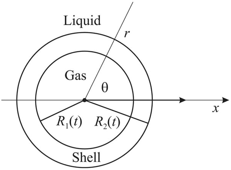
Schematic sketch of an encapsulated bubble.
A. Lagrangian equations
The Lagrangian equations are given by17
| (1) |
where L is the Lagrangian function, qi and q̇i are called generalized coordinates and velocities, respectively, and F is the dissipative function that is entered to account for dissipative effects such as viscosity. The Lagrangian function is defined as L=T–U, where T and U are the kinetic and potential energies of the system, respectively. Expressions for T, U, and F are sequentially calculated in the following subsections.
B. Kinetic energy
The kinetic energy can be represented as
| (2) |
where mb is the mass of the bubble, x(t) is the position of the center of the bubble in an inertial frame, the overdot denotes the time derivative, TL is the kinetic energy of the liquid, and TS is the kinetic energy of the shell.
It is shown in Ref. 18 that the kinetic energy of a slightly compressible liquid that encloses a spherical bubble with the time-varying radius R2(t), assuming also that the bubble can translate, is given by
| (3) |
where ρL is the equilibrium density of the liquid, c is the sound speed in the liquid, and . Note that if we substitute the explicit expression for ḟ(t) into Eq. (3), we will get a second-order time derivative of the radius in the third term in brackets, which is inadmissible in the Lagrangian formalism. To avoid this problem, ḟ(t) in will be TL treated just as a function of time and the explicit expression for f(t) will be used only in final equations. We will see below that this approach gives a correct result.
Assuming that the volume of the bubble shell, VS, remains constant in the process of bubble motion and that the effect of translation on the deformation of the shell is negligible, the velocity inside the shell can be written as
| (4) |
where R1(t) is the inner radius of the bubble shell. The kinetic energy of the shell is then calculated as
| (5) |
where ρS is the density of the shell. Applying to the shell the same approach that was used in Ref. 18 for calculating Eq. (3), it can be shown that compressibility corrections to Eq. (5) can not be lower order than , where cl denotes the longitudinal speed of sound in the shell. Note also that the assumption of incompressible shell gives the following equations, which will be used below,
| (6) |
where R10 and R20 are, respectively, the inner and the outer radii of the bubble shell at rest.
C. Potential energy
The total potential energy of the system can be written as the following sum:
| (7) |
Ug is the internal energy of the gas core. Assuming that the behavior of the gas is adiabatic, one has19
| (8) |
where Pg0 is the equilibrium pressure of the gas within the bubble, is the equilibrium gas volume, and γ is the ratio of specific heats.
The term Ust describes contributions due to surface tension at the gas-shell and the shell-liquid interfaces,
| (9) |
Here σ1 and σ2 denote the surface tension coefficients for the corresponding interfaces.
Uex is the contribution due to work done by the external pressure on the outer bubble surface. This contribution can be represented as
| (10) |
where P0 is the hydrostatic pressure in the liquid and Pac(x,t) is the acoustic pressure at the location of the bubble.
UL is the potential energy of the surrounding liquid due to its compressibility. It is shown in Ref. 18 that UL is given by
| (11) |
Finally, US is the elastic energy of the shell defined by
| (12) |
where ε is the elastic energy density which is given by20
| (13) |
Here μS and KS are respectively the shear modulus and the bulk modulus of the shell, δij is the Kronecker delta, uij is the linear strain tensor, and summation over double indices is implied. The linear strain tensor is defined as
| (14) |
with ui denoting the ith component of the displacement vector. Since the shell is assumed to be incompressible, which results in ukk =0, and in view of spherical symmetry, Eq. (13) takes the form
| (15) |
where u is the radial displacement. Using again the fact that the shell is incompressible, u can be written as
| (16) |
where R1e is the unstrained equilibrium position of the gas-shell interface. Note that R1e does not coincide with R10. The expression for R1e is calculated below.
Substitution of Eqs. (15) and (16) into Eq. (12) yields
| (17) |
As with TS, it can be shown that compressibility corrections to Eq. (17) are on the order and therefore they are neglected here.
D. Dissipative function
The total dissipative function of the system can be represented as
| (18) |
where VL is the volume occupied by the liquid, FL and FS are the dissipative functions of the liquid and the shell, and f L and f S are the densities of the dissipative functions.
For the surrounding liquid, f L, can be written as20,21
| (19) |
where ηL and ζL are, respectively, the shear and the bulk viscosity coefficients of the liquid, and vij is the rate-of-strain tensor of the liquid, defined as
| (20) |
with v denoting the liquid velocity. Neglecting the compressibility of the liquid, one has vkk = ∇ · v= 0 so Eq. (19) reduces to
| (21) |
To satisfy the boundary condition of adhesion of the liquid particles to the bubble surface, which is expressed as
| (22) |
the liquid velocity can be represented as v=∇ϕ+∇×ψ, where the scalar potential ϕ must obey the Laplace equation, Δϕ =0. Expressions for ϕ and ψ satisfying these two conditions are given by
| (23) |
| (24) |
The liquid velocity are then calculated as
| (25) |
Considering the form of Eq. (25), (vij)2 can be written as20
| (26) |
On substitution of Eq. (25) into Eq. (26), one has
| (27) |
Finally, integrating this equation over VL, one finds
| (28) |
Calculation of the dissipative function for the shell is much easier. For fS, one has 20
| (29) |
where ηS is the shear viscosity of the shell and vS is given by Eq. (4). Integrating Eq. (29), one obtains
| (30) |
E. Equations of motion
Calculating the functions L and F by using the equations obtained above, substituting the resulting expressions into Eq. (1), taking R1 and x as generalized coordinates, and using Eq. (6) to express R2 in terms of R1, one obtains the following equations of bubble motion:
| (31) |
| (32) |
Equation (31) governs the radial pulsation of the bubble and Eq. (32) its translation. The first term on the right-hand side of the translational equation is the acoustic radiation force and the second term is the viscous drag force in the form of the Stokes law, which is only natural as we used the no-slip boundary condition on the bubble surface. However, it is common practice to replace the Stokes drag force with a more accurate equation resulting from experimental measurements.
If the c−1 term on the left-hand side, the translational term ρLẋ2/(4ρS) on the right-hand side, and the (1–R1e/R1) correction within the square brackets in the elastic term on the right-hand side are omitted, Eq. (31) becomes identical to that obtained by Church.4 Note that Church’s theory implicitly supposes that the deformation of the shell is small and therefore the elastic term in Church’s radial equation is taken only to the first order in (1–R1e/R1). The (1–R1e/R1) correction in the elastic term partly extends the range of Eq. (31) towards finite deformations.
When the sound is off and the bubble is at rest, from Eq. (31) it follows that
| (33) |
Church used this equation, neglecting the (1–R1e/R1) correction in the elastic term, to get an expression for R1e. Assuming that the encapsulating layer is thin and fully permeable to gas, he set Pg0 = P0 and obtained
| (34) |
However, for thick-shelled contrast agents, such as Quantison and Myomap,3 it is unlikely that such an approximation will be appropriate. In the following subsection, a more correct calculation of R1e is given.
Next, ẋ in Eqs. (31) and (32) is in fact the velocity of the bubble with respect to the velocity of the surrounding liquid. That is, if there is a stream in the bulk liquid, due to the propagation of the acoustic wave, acoustic streaming, and so forth, ẋ should be replaced with ẋ– vex, where vex denotes the liquid velocity unrelated to the presence of the bubble.
It is easy to see that the compressibility correction, the c−1 term in Eq. (31), is similar to that obtained by Prosperetti for a free bubble.22 The striking feature of this term is the appearance of the third-order derivative R⃛2. This is just a consequence of using Taylor series expansions to express time-retarded quantities, e.g., R̈2(t–R2/c) ≈ R̈2(t) – (R2/c) R⃛2(t). The third derivative can be eliminated as follows. It is easily shown by using Eq. (6) that
| (35) |
i.e., R2 in the compressibility correction can be replaced with R1. Further, since the compressibility correction is already of order c−1, the right-hand side of Eq. (35) can be evaluated from Eq. (31) omitting the c−1 term. This results in
| (36) |
where G denotes the right-hand side of Eq. (31). On substitution of this equation into Eq. (31), the third derivative vanishes.
F. Expression for R1e
The radius R1e (as well as R2e for the outer interface) corresponds to the unstrained state of the shell material when any internal stresses within the shell are absent. Knowledge of R1e is necessary because by definition the displacement vector is reckoned from the unstrained position. Clearly R10 does not meet the unstrained state since even if the sound is off, stresses within the shell are not zero as there exists surface tension at the interfaces and in general P0 ≠ Pg0.
To calculate R1e, we need to know the strain distribution inside the shell when the sound is off. Solution to this problem can be found, for example, in Ref. 20. Applying it to the present case, one has
| (37) |
where
| (38) |
| (39) |
These equations give the strain distribution inside a resting spherical layer with inner and outer radii of R10 and R20. At r = R10, the deformation is equal to u1 = R10–R1e. Setting u = u1 and r = R10 in Eq. (37) and using Eq. (33), one obtains
| (40) |
Similarly, for R2e, one has
| (41) |
Equations (40) and (41) show that R1e < R10 and R2e < R20, i.e., the internal gas pressure expands the shell outwards with respect to its unstrained position. Note that , i.e., Church’s approximation predicts an opposite effect, namely that the shell shrinks due to surface tension with respect to its unstrained position. This discrepancy can be important because it affects the sign of the elastic term in Eq. (31). Note also that for the case of a free bubble, when the elastic term in Eq. (31) tends to zero as it must, whereas in Church’s theory this term tends to a finite quantity as is seen from Eq. (34).
Completing this main section, some remarks concerning the limits of validity of the proposed model should be made. Although no explicit restrictions are imposed on the amplitude of radial oscillation, the model, like the others mentioned in the Introduction, in fact is valid for moderate acoustic pressures at best. First, it ignores nonlinear elastic effects in the shell. Second, if compression is strong enough, the shell buckles. Even if the buckling is reversible, it is evident that the dynamics of the shell will change. If the buckling is irreversible, then the response of the bubble to repeating acoustic pulses can change. Third, the shell can break up during expansion and the bubble will lose gas. Finally, the bubble can also lose gas due to the shell permeability, the radial and translational motions of the bubble can be affected by a constrained environment of a blood vessel, etc. All these effects are still beyond the capabilities of existing models.
III. LINEAR ANALYSIS
Let us assume that the amplitude of the radial oscillation is small. Then we can write
| (42) |
where it is assumed that |ξ| <R10. Substituting Eqs.(42) into Eq. (31) and linearizing it with respect to ξ, one obtains the equation of a linear harmonic oscillator:
| (43) |
It is assumed in Eq. (43) that Pac(t) is of the form Pac(t) = Pa exp (iωt), where Pa is the acoustic pressure amplitude and ω is the angular driving frequency. The coefficient α, the damping constant δ, and the undamped linear resonance frequency ω0 are given by
| (44) |
| (45) |
| (46) |
| (47) |
| (48) |
| (49) |
It is instructive to compare these quantities to those obtained by Church.4 Differences are observed for δr, and ω0:
| (50) |
| (51) |
| (52) |
It should be noted that Eq. (50) was not formally derived by Church as part of Eq. (31); it was introduced by ad hoc assumption, modifying the relevant expression for a free bubble. The difference between Eqs. (48) and (51) is accounted for by Church’s assumption that Pg0 = P0 and his resulting expression for R1e, Eq. (34). Figures 2 and 3 show the ratios and as functions of R20. The solid lines in the figures correspond to the shell thickness RS =R20− R10=20 nm (Albunex bubble), and the dashed lines to RS =200 nm (Quantison bubble). The values of the physical parameters required for these calculations were taken from Church’s work:4 P0 =101.3 kPa, ρL =1000 kg/m3, ηL =0.001 Pa s, c=1500 m/s, ρS =1100 kg/m3, ηS =1.77 Pa s, μS =88.8 MPa, σ1 =0.04 N/m, and σ2 =0.005 N/m. Figures 2 and 3 show that the discrepancy with Church’s theory increases as the bubble radius decreases and the shell thickness increases, but is not very significant for bubbles with R20> 1 μm. However, it is known that the real resonance frequency of a system with dissipation differs from ω0 and depends on δ. The behavior of δr, and ω0 suggests that the damped (real) resonance frequency of an encapsulated bubble differs more significantly from that given by Church’s theory. To clarify this point, let us consider a solution to Eq. (43). This is
FIG. 2.
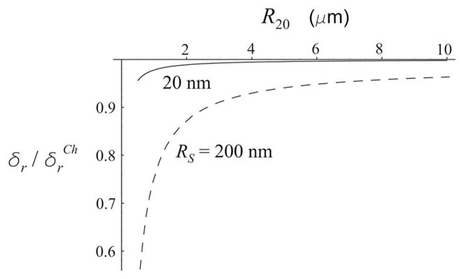
The ratio of the radiation damping constants as a function of equilibrium bubble radius for two values of the shell thickness RS.
FIG. 3.
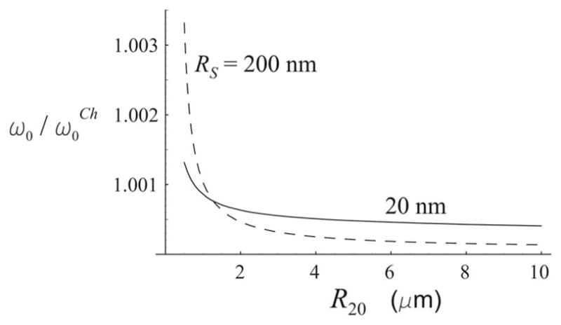
The ratio of the undamped resonance frequencies as a function of equilibrium bubble radius for two values of the shell thickness RS.
| (53) |
where
| (54) |
| (55) |
| (56) |
The resonance response corresponds to a maximum of Q(ω). If δ is independent of ω, the damped resonance frequency is equal to . However, in the present case δr is frequency dependent and therefore ωr is defined by a more complicated expression
| (57) |
where β=δr/ω2=ρLR10/(αcρS). The value of the damped resonance frequency given by Church’s theory, , is obtained from Eq. (57) by replacing ω0 with and β with βCh=R20/c. Figure 4 shows the ratio as a function of R20 for the same values of the parameters as in Fig. 3. Figure 5 presents the absolute values of the damped resonance frequency f r = ωr/2π; the dashed line corresponds to a free bubble of the equivalent size. It is seen from Fig. 4 that the ratio is really noticeably larger than the ratio in Fig. 3. Figure 5 points to one more feature of damped oscillations, which is not considered in Church’s analysis, namely that strong damping can lead to the absence of resonance. This occurs when the expression in brackets in Eq. (57) becomes negative, which in turn results from the fact that δη very strongly increases as the bubble radius decreases. It is for this reason that the solid lines in Fig. 5 go down and stop at small values of R20, and the corresponding lines in Fig. 4 are terminated at approximately 3.5 and 2 μm. Figure 6 illustrates the process of vanishing resonance response, showing the function Q(ω) at RS =20 nm for various values of R20. It is seen that when R20 is smaller than a threshold value, the resonance peak is absent and the amplitude of the radial oscillation monotonically decreases as the driving frequency increases. Figure 5 also shows that the thicker the bubble shell, the larger the threshold bubble radius.
FIG. 4.

The ratio of the damped resonance frequencies as a function of equilibrium bubble radius for two values of the shell thickness RS.
FIG. 5.

Damped resonance frequency f r = ωr/2π versus equilibrium bubble radius for two values of the shell thickness RS. The dashed line corresponds to a free bubble of the equivalent size.
FIG. 6.
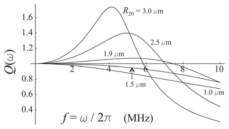
Behavior of the resonance function Q(ω) at RS =20 nm for various values of the equilibrium bubble radius R20.
IV. COMPARISON WITH ZERO-THICKNESS ENCAPSULATION MODELS
Most of the existing models having the form of a Rayleigh-Plesset-type equation can be referred to as zero-thickness encapsulation models, since these, explicitly or implicitly, assume the bubble shell to be very thin and describe only the dynamics of the outer bubble radius. If we neglect the translational term in Eq. (31) and assume that ρS ≈ ρL, the deformation of the shell is small, and RS Lt; R10, R20, Eq. (31) reduces to an equation of the above-named type:
| (58) |
where R denotes the outer bubble radius and σ=σ1 + σ2. It is easy to see that Eq. 3583 is practically identical to the equation proposed by de Jong et al. for Albunex microspheres1,2 provided that
| (59) |
where Sp and Sf are, respectively, the shell elasticity parameter and the shell friction parameter that appear in de Jong et al.’s model. Using Eqs. (59) and the results of de Jong et al., we can estimate values of μS and ηS for albumin-shelled bubbles. Assuming RS =15 nm, one has μS =88.8 MPa and ηS =1.77 Pa s, in agreement with Church’s estimates.4 By using Ref. 23, the parameters Sp and Sf can also be evaluated for lipid-shelled bubbles. For example, setting RS =1 nm as is proposed by Morgan et al.6 for lipid coatings, one finds μS =333.3 MPa and ηS =2.4 Pa s. Note that the value of ηS is of the same order of magnitude as that obtained by Morgan et al.6 by fitting experimental radius-time curves. As regards the elastic term used in the model of Morgan et al., Marmottant et al.23 have recently shown that it is incorrect. Therefore comparison of the value of μS is impossible.
Marmottant et al.23 also showed that for lipid-shelled bubbles, the elastic behavior of the bubble shell can occur only for very small oscillations of the bubble radius about its equilibrium value. For larger oscillations, the shell buckles when the bubble is compressed and breaks up when the bubble expands. Therefore a continuous elastic model like Eq. (58) is not a good approximation for lipid-shelled contrast agents. However, for bubbles with a sufficiently thick encapsulation, such as polymer- or albumin-shelled contrast agents, Eqs. (31) and (32) can be quite adequate.
V. RADIATION FORCE AND TRANSLATIONAL MOTION
In this section, we apply Eqs. (31) and (32) to calculate the radiation force experienced by an encapsulated bubble and the translational displacement of the bubble due to this force. Let us first consider radiation force in a weak field, assuming that the radial oscillation of the bubble is described by Eq. (43). The radiation force exerted on the bubble can be calculated as
| (60) |
where 〈〉 means the time average and r is the position vector of the bubble centroid. Substituting R2(t) from Eq. (42), one obtains
| (61) |
In the case of a plane traveling wave, Pac(r,t) = Pa exp (iωt −ik·r), where k=ω/c is the wave vector. Substituting this expression into Eq. (43), one finds ξ(t) to be
| (62) |
Substitution of Eq. (62) into Eq. (61) finally yields
| (63) |
The radiation force on a free bubble of the equivalent radius is given by24
| (64) |
where
| (65) |
| (66) |
Figure 7 displays the ratio Ffr/Fen as a function of driving frequency for three bubbles with different values of equilibrium radius and shell thickness. The presence of encapsulation decreases the amplitude of the radial oscillation of contrast agent bubbles. For this reason, it is commonly supposed that the radiation force on an encapsulated bubble should be considerably smaller than that on a free bubble of the equivalent size. Figure 7 reveals, however, that this is not true throughout the whole frequency range. At relatively low frequencies, near the resonance of the free bubble, the radiation force on the free bubble is really much larger than that on the encapsulated bubbles. However, for higher frequencies, in the range of resonances of the encapsulated bubbles, the radiation force on the encapsulated bubble exceeds that on the free bubble. Curve 3 shows that this effect can occur even for a thick-shelled bubble with RS =200 nm if its outer radius is large enough.
FIG. 7.
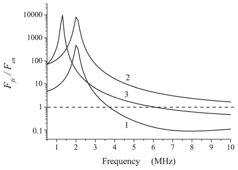
Comparison of radiation force experienced by an encapsulated bubble in a weak field with that on a free bubble of the equivalent size at various driving frequencies. (1) R20=2 μm, RS =15 nm; (23 R20=2 μm, RS =200 nm; and (3) R20=3 μm, RS =200 nm.
Figure 8 shows the translational displacement of a free bubble (dashed line) and two equivalent encapsulated bubbles with RS =15 nm and 200 nm under stronger driving. The bubbles are subjected to a single 20-cycle acoustic pulse with a pressure amplitude of 150 kPa. The displacement is fixed after the termination of the pulse. The outer radius of all the bubbles is 2 μm. The simulation was carried out by numerically calculating Eqs. (31) and (32). It is again seen that at high frequencies the displacement of the encapsulated bubbles is considerably larger, this time even for the 2-μm-radius bubble with RS =200 nm. Thus, it is found that in the range of relatively high frequencies encapsulated bubbles are able to translate more efficiently than free bubbles of equivalent size.
FIG. 8.
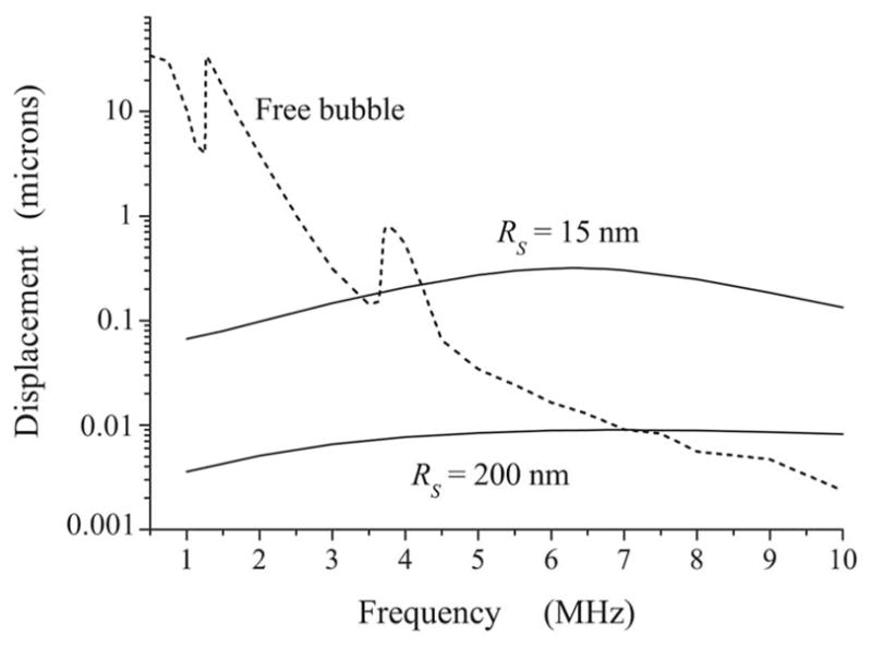
Translational displacement versus driving frequency for a free and an encapsulated bubble. The driving field is a single 20-cycle acoustic pulse with a pressure amplitude of 150 kPa. The displacement is fixed after the termination of the pulse. The outer radius of the bubbles is 2 μm.
VI. CONCLUSIONS
In this work coupled equations describing the radial and translational dynamics of an encapsulated gas bubble are derived. It is assumed that the encapsulating layer is an incompressible elastic solid with viscous damping and the surrounding medium is a slightly compressible viscous Newtonian liquid. The proposed model improves Church’s theory4 by allowing for the translation motion of the bubble and radiation losses due to the compressibility of the surrounding liquid. It is also shown that the expression obtained by Church for the inner bubble radius corresponding to the unstrained state of the encapsulating shell gives an incorrect result when the shell thickness tends to zero. The expression for the unstrained radius is recalculated by using equations from the theory of elasticity.
Comparative analysis of the linearized radial equation is carried out relative to Church’s theory. In the course of the analysis, the expression for the acoustic damping constant of an encapsulated bubble is refined, and it is shown that Church’s theory underestimates the damped resonance frequencies of encapsulated bubbles. It is also shown that the viscous damping in the bubble shell can lead to the absence of resonance response. This effect is observed when the bubble radius is smaller than a threshold value; the thicker the bubble shell, the larger the threshold bubble radius. Below the threshold radius, the amplitude of the radial oscillation monotonically decreases as the driving frequency increases.
The acoustic radiation force experienced by an encapsulated bubble in a weak field is calculated analytically and compared with the radiation force on a free bubble of the equivalent size. It is shown that for high frequencies, the radiation force on the encapsulated bubble exceeds that on the free bubble. For the case of stronger driving, comparison of the radiation forces is carried out by numerically calculating the translational displacement of the bubbles, using the nonlinear coupled equations of the radial and translational motions. It is shown again that at high frequencies the displacement of encapsulated bubbles is considerably greater than that of free bubbles of equivalent size.
Acknowledgments
A.A.D. wishes to acknowledge the financial support of the International Science and Technology Center (ISTC) under Contract No. B-1213.
Contributor Information
Alexander A. Doinikov, Institute of Nuclear Problems, Belarus State University, 11 Bobruiskaya Street, Minsk 220050, Belarus.
Paul A. Dayton, Department of Biomedical Engineering, University of California, 451 East Health Sciences Drive, Davis, California 95616.
References
- 1.de Jong N, Cornet R, Lancee CT. Higher harmonics of vibrating gas-filled microspheres. Part one: simulations. Ultrasonics. 1994;32:447–453. [Google Scholar]
- 2.de Jong N, Hoff L. Ultrasound scattering of Albunex microspheres. Ultrasonics. 1993;31:175–181. doi: 10.1016/0041-624x(93)90004-j. [DOI] [PubMed] [Google Scholar]
- 3.Frinking PJA, de Jong N. Acoustic modeling of shell-encapsulated gas bubbles. Ultrasound Med Biol. 1998;24:523–533. doi: 10.1016/s0301-5629(98)00009-x. [DOI] [PubMed] [Google Scholar]
- 4.Church CC. The effect of an elastic solid surface layer on the radial pulsations of gas bubbles. J Acoust Soc Am. 1995;97:1510–1521. [Google Scholar]
- 5.Vokurka K. Comparison of Rayleigh’s, Herring’s, and Gilmore’s models of gas bubbles. Acustica. 1986;59:214–219. [Google Scholar]
- 6.Morgan KE, Allen JS, Dayton PA, Chomas JE, Klibanov AL, Ferrara KW. Experimental and theoretical evaluation of microbubble behavior: Effect of transmitted phase and bubble size. IEEE Trans Ultrason Ferroelectr Freq Control. 2000;47:1494–1509. doi: 10.1109/58.883539. [DOI] [PubMed] [Google Scholar]
- 7.Dayton PA, Allen JS, Ferrara KW. The magnitude of radiation force on ultrasound contrast agents. J Acoust Soc Am. 2002;112:2183–2192. doi: 10.1121/1.1509428. [DOI] [PubMed] [Google Scholar]
- 8.Lamb H. Hydrodynamics. Cambridge: U. P., Cambridge; 1957. [Google Scholar]
- 9.Voinov OV, Petrov AG. Motion of a sphere of changing volume in an ideal fluid near a flat surface. Izv Akad Nauk SSSR, Mekh Zhidk Gaza. 1971;5:94–103. [Google Scholar]
- 10.Ceschia M, Nabergoj R. On the motion of a nearly spherical bubble in a viscous liquid. Phys Fluids. 1978;21:140–142. [Google Scholar]
- 11.Chakraborty BB, Tuteja GS. Motion of an expanding, spherical gas bubble in a viscous liquid under gravity. Phys Fluids A. 1993;5:1879–1882. [Google Scholar]
- 12.Luther S, Mettin R, Lauterborn W. Modeling acoustic cavitation by a Lagrangian approach. In: Lauterborn W, Kurz T, editors. Proceedings of the 15th International Symposium on Nonlinear Acoustics; Melville, NY: AIP; 2000. pp. 351–354. [Google Scholar]
- 13.Doinikov AA. Translational motion of two interacting bubbles in a strong acoustic field. Phys Rev E. 2001;64(2):026301. doi: 10.1103/PhysRevE.64.026301. [DOI] [PubMed] [Google Scholar]
- 14.Doinikov AA. Translational motion of a spherical bubble in an acoustic standing wave of high intensity. Phys Fluids. 2002;14:1420–1425. [Google Scholar]
- 15.Doinikov AA. Mathematical model for collective bubble dynamics in strong ultrasound fields. J Acoust Soc Am. 2004;116:821–827. [Google Scholar]
- 16.Zabolotskaya EA, Ilinskii YuA, Meegan GD, Hamilton MF. Modifications of the equation for gas bubble dynamics in a soft elastic medium. J Acoust Soc Am. 2005;118:2173–2181. doi: 10.1121/1.2010348. [DOI] [PubMed] [Google Scholar]
- 17.Landau LD, Lifshitz EM. Mechanics. Pergamon; Oxford: 1976. [Google Scholar]
- 18.Doinikov AA. Equations of coupled radial and translational motions of a bubble in a weakly compressible liquid. Phys Fluids. 2005;17(12):128101. [Google Scholar]
- 19.Emelianov SY, Hamilton MF, Ilinskii YA, Zabolotskaya EA. Nonlinear dynamics of a gas bubble in an incompressible elastic medium. J Acoust Soc Am. 2004;115:581–588. doi: 10.1121/1.1621858. [DOI] [PubMed] [Google Scholar]
- 20.Landau LD, Lifshitz EM. Theory of Elasticity. Pergamon; Oxford: 1986. [Google Scholar]
- 21.Landau LD, Lifshitz EM. Fluid Mechanics. Pergamon; Oxford: 1987. [Google Scholar]
- 22.Prosperetti A. The equation of bubble dynamics in a compressible liquid. Phys Fluids. 1987;30:3626–3628. [Google Scholar]
- 23.Marmottant P, van der Meer S, Emmer M, Versluis M, de Jong N, Hilgenfeldt S, Lohse D. A model for large amplitude oscillations of coated bubbles accounting for buckling and rupture. J Acoust Soc Am. 2005;118:3499–3505. [Google Scholar]
- 24.Doinikov AA. Bjerknes forces and translational bubble dynamics. In: Doinikov AA, editor. Bubble and Particle Dynamics in Acoustic Fields: Modern Trends and Applications. Research Signpost; Trivandrum, Kerala: 2005. pp. 95–143. [Google Scholar]