

Abstract
Tubular membrane structures are widespread in eukaryotic cells, but the mechanisms underlying their formation and stability are not well understood. Previous work has focused on tube extrusion from cells and model membranes under the application of external forces. Here, we present novel membrane/polymer systems, where stable tubes form in the absence of externally applied forces. Solutions of two water-soluble polymers, polyethylene glycol and dextran, were encapsulated in giant lipid vesicles, cell-size model systems. Hypertonic deflation induced phase separation of the enclosed solution. The excess membrane area created during the deflation process was stored in a large number of membrane nanotubes inside the vesicle. The tubes had a diameter below optical resolution and became visible only when fluorescently labeled. The tubes were rather stable: In the absence of external forces, they existed for several days. A theoretical analysis of the shapes of the deflated vesicles reveals that these shapes would be unstable if the membranes had no spontaneous curvature. Using the large separation of length scales between the tube diameter and the overall size of the vesicles, the spontaneous curvature can be calculated and is found to be about -1/(240 nm) for a certain range of polymer concentrations. The nanotubes could also be retracted back into the mother vesicle by increasing the membrane tension via micropipette aspiration of the vesicle. Membrane tubes, which can form and be retracted easily, should be relevant for lipid storage in cells.
Keywords: biomimetic systems, molecular crowding, polymer–membrane interactions, membrane morphologies, morphological transitions
Eukaryotic cells often contain tubular membrane structures, also known as tethers or membrane nanotubes, with dimensions ranging from a few microns in diameter (myelin structures) to a few tens of nanometers. They are constantly formed in the Golgi apparatus and in mitochondria (1, 2), as well as in the smooth endoplasmic reticulum (ER), a tubular membranous structure (3) with tube diameter of 50–150 nm. There, newly synthesized lipids have to be stored before being transferred to their target destinations. Folding excess membrane into tubes provides a very efficient way to store this membrane, because the tubes are characterized by a relatively large area to volume ratio.
In a number of studies, tubes have been pulled from cells and model membranes by applying an external force via fluid drag (4–7), gravity (8), micropipette systems (9, 10), or optical (11, 12) and magnetic tweezers (13, 14). The forces needed for pulling membrane tubes from Golgi or ER membranes are ∼10 pN (15). In all of these studies, tube formation required the local application of an external force.
Here, we describe a simpler process that does not involve such an external force but may also play a role in organizing the membrane of cellular organelles into tubular structures. We show that local phase separation within macromolecular solutions can restructure smooth membranes into tubular structures. After formation, these tubes are stable even after phase separation has been completed.
The interior of living cells is crowded with macromolecules and organelles. The weight fraction of proteins, RNAs, and polysaccharides is on the order of 20–30%. In such a concentrated environment, local phase separation may occur, involving local composition differences and microcompartmentation, affecting, e.g., cell functioning and the performance of cytoplasmic proteins (16, 17). Recently, giant lipid vesicles with a diameter of several micrometers (18) and loaded with polymer solutions were reported to exhibit internal phase separation (19–21). The polymer weight fractions were comparable to those in cells. We employ these cell-sized biomimetic systems to study the reorganization of membranes arising from molecular crowding.
As a simplistic model of the cytoplasmic medium, we used solutions of the water-soluble macromolecules polyethylene glycol (PEG) and dextran. Solutions containing both polymers undergo phase separation at concentrations above a few weight percents. We prepared vesicles containing the polymer solution in the one-phase state. By exposing them to a hypertonic medium, phase separation was induced in their interior. The excess membrane produced by deflation formed nanotubular structures. The tubes, which had a diameter below optical resolution and became visible only when fluorescently labeled, were very stable in the absence of external forces. A stability analysis reveals that the observed vesicle shapes would be unstable if the membranes had no spontaneous curvature. Using the large separation of length scales between the tube diameter and the overall size of the vesicles, the spontaneous curvature can be calculated and is found to be about -1/(240 nm) for a certain range of polymer concentrations. The tubes could also be recruited back to the “mother” vesicle membrane by subjecting it to mild tensions.
Experimental Results
Deflation Trajectories in the Phase Diagram.
We prepared vesicles encapsulating two different PEG–dextran solutions in the one-phase state: one with a larger fraction of PEG (4.05 wt% PEG and 2.22 wt% dextran) and the other with a larger fraction of dextran (2.10 wt% PEG and 7.44 wt% dextran). As indicated in Fig. 1, we will refer to these two solutions as Sp and Sd, respectively. Upon exposure to hypertonic medium (see Materials and Methods and Table S1), the vesicles are deflated and the internal polymer concentration is raised above the binodal. The vesicle deflation is described by the osmolarity ratio r = Pe/P0, where Pe is the osmolarity of the external solution and P0 is the initial osmolarity inside the vesicle. After phase separation, Sp vesicles have a larger PEG-rich phase (p) and Sd vesicles have a larger dextran-rich phase (d); the external medium will be denoted by e (see Fig. 1A). The PEG-rich phase is lighter, located at the vesicle top (Fig. 1B), and can completely or partially wet the membrane (21, 22). From side-view observations, we measure the vesicle apparent area and volume and deduce the polymer concentrations inside the vesicle at each deflation step; for example, see Fig. 1B.
Fig. 1.

(A) Phase diagram of the PEG-dextran polymer solution. The black squares indicate the binodal measured at 23 °C (the solid line is a guide to the eye). Below the binodal, the polymer solution is homogeneous; above the binodal, it undergoes phase separation. The dashed lines indicate experimental deflation trajectories of vesicles initially loaded with aqueous solutions of composition Sp (red star) and Sd (green star). The Insets schematically illustrate possible vesicle shapes. The external medium (e), the PEG-rich phase (p), and the dextran-rich phase (d) are indicated in the upper cartoon. (B) Phase contrast images of side-view observation of a deflated Sp vesicle. The image numbers correspond to the concentration conditions indicated with 1 to 3 in A, and their respective osmolarity ratios are r = 1.24, 1.46, and 1.65. The dense, lower part is the dextran-rich phase; see corresponding cartoon in A.
Microscopy Observations of Membrane Tube Formation.
The excess membrane created during vesicle deflation forms tubular structures in the vesicle interior. This process can be directly observed for vesicles with fluorescently labeled membranes (see Fig. 2). Before deflation, no fluorescence is detected in the vesicle interior (Fig. 2A). When the osmolarity of the external medium is increased by the addition of hypertonic solution, phase separation is initiated and small droplets of dextran-rich phase are observed inside the vesicle (see Fig. 2B). After phase separation is completed, a collection of membrane tubes always in contact with the PEG-rich phase is observed (Fig. 2 C and D). At higher osmolarity ratio r, the excess membrane adsorbs at the two-phase interface forming a layer or meshwork of tubes (Fig. 2 E and F). When the interface becomes overcrowded, hundreds of tubes protrude into the PEG-rich phase (Fig. 2 G and H). As the excess area of the membrane increases and the contact area between the PEG-rich and dextran-rich phases decreases, the interface becomes overcrowded and the tubes start to protrude partially into the PEG-rich phase (see Fig. 2 G and H). Confocal scans of the horizontal plane slightly above the interface in this vesicle show circular tube cross-sections with a diameter of about 1 μm for this osmolarity ratio (see Fig. 2I).
Fig. 2.

Tube formation in Sp vesicles. (A–C) Overlay of top-view confocal sections and bright field images of a vesicle (A) before deflation, (B) during phase separation, and (C) after 2.6 h of equilibration. The arrowheads in B and C indicate fluorescence from tubes in the focal plane. The droplets visible in B contain the newly formed dextran-rich phase. In C, the inner dark circle represents the contour of the dextran-rich phase, which is in focus. The out-of-focus outer dark circle is the contour of the PEG-rich phase above the dextran-rich phase. The fluorescent signal shows the membrane crossing the focal plane. (D) Confocal xy section of another vesicle showing possible three-way tube junctions indicated by arrows as in F. For C and D, the osmolarity ratio r = 1.24. (E) Vertical xz section showing adsorption of tubes onto the two-phase interface. (F) Horizontal xy section at the z position of the arrowhead in E showing tubes at the two-phase interface. (G) Vertical xz section of a vesicle with overcrowded two-phase interface; the tubes protrude into the upper PEG-rich phase. (H) 3D projection from a stack of xy sections at the two-phase interface delimited by the rectangle in G. (I) Confocal xy section of the tubes slightly above the two-phase interface. For E–I, r = 1.5. Scale bars, 15 μm.
The membrane tubes are rather stable and can exist for days. Tube formation is always induced by phase separation. Tubes form in approximately 95% of the deflated vesicles in all systems we have explored (see SI section Statistics of the Membrane Tube Formation in Deflated Vesicles and Figs. S1–S4). When tubes are not observed after the initial deflation step, they are observed upon further deflation when phase separation within the droplets occurs. The external solution does not affect the tube formation. Tubes form in vesicles diluted and deflated by sucrose solution. We also explored the behavior of vesicles encapsulating solutions without phase separation, such as aqueous sucrose solution and PEG solution. No tubes are observed in these cases.
Evolution of Membrane Area Under Deflation.
The axial symmetry of the vesicles allows us to evaluate the apparent area of the mother vesicle, A, from side-view observations. The area of the formed tubes is A0 - A, where A0 is the initial area for osmolarity ratio r = 1. Different behavior can be distinguished in the evolution of the vesicle apparent area (see Fig. 3A). Upon deflation of Sp vesicles, A first decreases. Additional tubes stop forming for r > 1.2. Instead, the newly created excess area leads to budding, during which the smaller dextran-rich droplet protrudes out of the initially spherical vesicle body (Fig. 1B).
Fig. 3.

Area and shape evolution in deflated vesicles. (A) Change in the apparent vesicle area A rescaled by the one before deflation, A0 (r = 1), for vesicles initially encapsulating Sp (red) and Sd (green). The cartoons illustrate typical vesicle shapes after the first few deflation steps, corresponding to osmolarity ratio r ≅ 1.4. Before each deflation step, the solutions were left to equilibrate about 2 h for the Sp vesicles, and about 4 h for the Sd vesicles. (B–E) Fluorescence images of deflated Sd vesicles. During deflation from r = 1.4 (B) to r = 1.5 (D), the lower vesicle part adopts intermediate raspberry-like shapes, as shown by the fluorescence microscopy image (C) and a confocal xz section (E); note that the images in B–D and E are from two different vesicles. Arrowheads in B, D, and E indicate fluorescence from tubes at the two-phase interface. Scale bars, 20 μm.
The apparent area of Sd vesicles decreases for osmolarity ratio r < 1.3 but then returns to its original value. The subsequent increase indicates tube receding. In this r range, interesting intermediate vesicle shapes are observed during deflation (Fig. 3 B–E). The excess membrane area spreads over the newly formed PEG-rich droplets (which might be nucleated at the membrane) within the dextran-rich phase. The droplets protrude out of the vesicle body, and the lower part of the vesicle adopts a metastable raspberry-like shape (Fig. 3 C and E). The formation of these protrusions increases the membrane tension, leading to tube retraction for r≥1.3 (Fig. 3A). The raspberry-like surface is observed only for the membrane segment in contact with the lower dextran-rich phase, because the interaction energy between the PEG-rich phase and the membrane is lower. These intermediate raspberry-shaped vesicles are observed at every deflation step. The PEG-rich droplets newly formed in the dextran-rich phase slowly cream upward along the membrane and coalesce with the PEG-rich phase at the vesicle top, leaving a smooth dextran-rich phase beneath (see Fig. 3D). In the equilibrated vesicles, the membrane tubes, if present, are adsorbed at the two-phase interface (see arrows in Fig. 3 B and D). The number of tubes at this interface seems to decrease for r > 1.3, consistent with the behavior of the vesicle apparent area in Fig. 3A. Instead, the excess membrane is utilized to perform overall morphological changes. At r ≅ 1.6 both polymer phases are complete spheres (dumbbell-like vesicle) with no detectable interface (see Fig. S2).
Membrane Tube Retraction.
As mentioned above, the tube retraction can be initiated by increased tension in the membrane. We demonstrate this by applying aspiration pressure via micropipettes to predeflated vesicles with tubes (see Fig. 4, SI section Calculation of Membrane Tension and Vesicle Apparent Area During Micropipette Aspiration, and Fig. S5). The fluorescence signal in the interior of an Sp vesicle shows tubes accumulated at the two-phase interface and extending into the PEG-rich phase (see arrows in Fig. 4A). The suction pressure applied to the vesicle part wetted by the PEG-rich phase (Fig. S5) defines the tension of this membrane segment,  . The area change A - Ain, where
  is the initial outer area of the vesicle before applying a suction pressure, corresponds to the membrane retracted from tubes. Three distinct regimes are observed in the evolution of the apparent vesicle area (see Fig. 4).
Fig. 4.

Change in the apparent area of an Sp vesicle caused by tube retraction when the membrane tension is increased via micropipette aspiration. The vesicle was initially predeflated to osmolarity ratio r = 1.4. The tension threshold 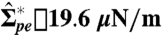 necessary to initiate tube retraction is indicated by an arrow. The fluorescence images show side views of the vesicle (A) before and (B–D) after applying a suction pressure. The images correspond to the points indicated in the graph. The arrowheads in A point to tubes accumulated at the pd interface and extending into the PEG-rich phase. In B–D, the micropipette tip is visible as well as the aspirated vesicle part indicated by arrowheads. At high tensions, no tubes are detected at the two-phase interface (D).
In the low tension regime, the apparent area increases very weakly. No detectable change of the fluorescent signal is observed in the vesicle interior (see Fig. 4 A and B). Above the tension threshold 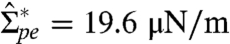 (measured on different vesicles
  ), the vesicle apparent area increases significantly by about 15%, accompanied by a decrease in the fluorescence signal from the tubes. Note that this area change arising from the tube retraction corresponds very well to the area decrease measured in the vesicle deflation experiments in Fig. 3 (see data for the Sp vesicle, which upon deflation from r = 1 to r = 1.4 shows a 13% area decrease). In some experiments, the cylindrical part of the vesicle inside the pipette is observed to bud off and form a small vesicle reflecting the relatively large excess area. Budding terminates the measurement at this stage. In the third regime,
  , the apparent area hardly changes, the tubes have been retracted, and no fluorescent signal is detected inside the vesicle (Fig. 4D).
Theoretical Analysis
Geometry of Deflated Vesicles.
After phase separation inside the vesicle, the two droplets of PEG-rich (or p) phase and dextran-rich (or d) phase are separated by the pd interface. In general, this interface may or may not be in touch with the vesicle membrane depending on the wetting properties of the system. For the exceptional case of complete wetting of the membrane by the PEG-rich phase, the vesicle is spherical and the pd interface has no contact with the membrane. For the typical case of partial wetting by the PEG-rich phase as in Figs. 1, 3, and 4, this membrane will consist of two segments: the pe membrane segment between the p droplet and the external (or e) phase, and the de membrane segment between the d droplet and the e phase. Both the pd interface and the two membrane segments form spherical caps, which meet at the contact line.
The pd interface pulls the membrane along the contact line with the interfacial tension Σpd. In mechanical equilibrium, this force must be balanced by two membrane tensions,  and
and  , acting tangential to the pe and de membranes, respectively. In spite of these latter tensions, the membrane area remains essentially unchanged during the deflation process (see SI section Membrane Tensions and Area Dilation) and, thus, has the constant value A0 as measured for the initial, spherical vesicle. In contrast, the apparent area of the vesicle, which represents the combined area of the pe and de membrane caps as observed in the optical microscope, is substantially reduced during the deflation process, as shown in Fig. 3. This reduction reflects the formation of hidden membrane area in the form of nanotubes, which have a diameter below optical resolution and become visible only when fluorescently labeled. The total area Atu of the nanotubes can be obtained by subtracting the apparent area from the total area A0. For the images shown in Fig. 1B, the tube area Atu is then found to be of the order of a few thousand square micrometers.
Elastic Properties of Membrane Segments.
Both membrane tensions  and
and  can be decomposed into two contributions. One contribution arises from the constraints on the area of the membrane segments (22); the other contribution is induced by the spontaneous curvatures, mpe and mde, of these segments, as previously discussed for uniform membranes (see, e.g., ref. 23). More precisely, the two membrane tensions may be written as
| [1] |
where the first terms, Σpe and Σde, arise from the area constraints and the second terms depend on the spontaneous curvatures and on the bending rigidity κ.
For the membranes studied here, the bending rigidity κ has been measured by flickering spectroscopy (see SI section Bending Rigidity Measurement Using Fluctuation Analysis) and was found to be κ ≅ 10-19 J. The spontaneous curvatures of the different membrane segments are both difficult to measure and difficult to estimate a priori because they depend, in general, on the details of the molecular structure. Therefore, it is appealing to assume that the two spontaneous curvatures mpe and mde are negligible (22). However, the latter assumption is not consistent with our experimental observations as we will now demonstrate in two ways. First, in the absence of spontaneous curvature, the observed vesicle shapes are unstable with respect to a shortening of the membrane tubes. Second, using the large separation of length scales between the curvature radii of the spherical membrane caps and the membrane nanotubes, the spontaneous curvature mpe can be estimated in terms of experimentally accessible quantities.
Shape Instability in the Absence of Spontaneous Curvature.
Each surface segment of the vesicle makes a certain contribution to the vesicle’s free energy. The contribution from the pd interface is proportional to the interfacial area Apd and given by Fpd = ApdΣpd. Likewise, if the spontaneous curvature mpe of the pe membrane segment vanishes, the contribution from the nanotubes, which are composed of pe segments, has the form Ftu = AtuΣpe (see SI section Bending Energy of Cylindrical Nanotubes). In contrast, the bending energies of the spherical membrane caps are not proportional to the cap areas but have a combined value of the order of 8πκ irrespective of the cap sizes.
Using the measured value κ ≅ 10-19 J of the bending rigidity, we find Fpd ∼ Ftu ∼ 10-14 J, whereas the bending energy of the spherical membrane caps is only approximately 10-18 J. Therefore, if the spontaneous curvature of the membranes were negligible, the free energy of the vesicle would be dominated by the free energy Fpd of the pd interface and the bending energy Ftu of the pe nanotubes. However, such a situation is intrinsically unstable because we could reduce the vesicle free energy by transferring membrane area from the nanotubes to the spherical membrane caps. For the vesicles shown in panels 2 and 3 of Fig. 1B, for example, we could use the transferred area to extend both the pe membrane cap and the de membrane cap in such a way that these extensions cover the outer part of the pd interface. As a result, the contact line would move toward the vesicle interior, and the interfacial area Apd would decrease. We then let the two droplets relax until they again adopt spherical cap shapes. A systematic stability analysis shows that such a transfer of membrane area is indeed possible for fixed volumes of the p and d droplets, even if one takes the force balance along the contact line into account. During such a transfer process, both the area Atu of the tubes and the area Apd of the pd interface are reduced simultaneously, which implies an overall reduction of the vesicle free energy. Therefore, for mpe = 0, the observed vesicle shapes would be unstable with respect to a shortening of the nanotubes.
Cylindrical Nanotubes.
If the nanotubes have a cylindrical shape with radius Rcy, they are characterized by constant mean curvature Mcy = -1/2Rcy, which is negative here because the tubes are located inside the vesicles. The spherical pe cap with curvature radius Rsc,pe, on the other hand, has the positive mean curvature Msc,pe = 1/Rsc,pe. The mechanical equilibrium between these two types of membrane segments can be described, for Rsc,pe≫Rcy, by relatively simple equations as derived in ref. 24 for membranes without spontaneous curvature. Extending these theoretical considerations to the systems studied here (see SI section Derivation of Eqs. 2 and 3), the mean curvature Mcy of the membrane tubes and the spontaneous curvature mpe of the pe membrane are found to satisfy the simple relation
| [2] |
In the same limit, the spontaneous curvature mpe is given by
| [3] |
which depends on the membrane tension  , the bending rigidity κ, and the curvature radius Rsc,pe. Comparing the asymptotic equality 3 with the general expression 1 for the tension
  , one concludes that this tension is dominated by the term
  arising from the spontaneous curvature and that the other term Σpe ∼ κmpe/Rsc,pe represents a small correction. As explained in SI section Membrane Tensions and Area Dilation, the membrane tension
  can be calculated from the measured interfacial tension Σpd and the (effective) contact angles. For the vesicles shown in panels 2 and 3 of Fig. 1B, for instance, one then obtains the membrane tension
 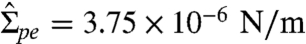 and 3.99 × 10⁻⁶ N/m, respectively. The measured radii Rsc,pe are 39.3 and 37.6 μm, respectively, and the bending rigidity κ = 1.13 ± 0.22 × 10⁻¹⁹ J (see SI section Bending Rigidity Measurement Using Fluctuation Analysis). It then follows from relation 3 that the pe membranes of the two vesicles have a spontaneous curvature mpe = -1/(245 ± 96 nm) and -1/(238 ± 93 nm), respectively. This result is confirmed by an analysis of two other vesicles that have been observed for similar osmolarity conditions. Furthermore, inserting these values for mpe into Eq. 2, the radii of the membrane nanotubes are found to be Rcy = 122 ± 48 and 119 ± 46 nm for the two cases.
Necklace-Like Morphology of Nanotubes.
In the previous subsection, the nanotubes were assumed to have a cylindrical shape. In analogy to the classical Rayleigh–Plateau instability of liquid cylinders, one might expect that cylindrical membrane nanotubes could reduce their free energy by transforming into a string of small spheres. A liquid cylinder of constant volume is unstable with respect to such a transformation because a string of spherical droplets has a smaller interfacial area and, thus, a smaller interfacial free energy. Thus, let us consider a membrane nanotube that consists of a necklace-like string of small spheres with radius Rss, which are connected by very thin membrane necks. Because the spheres are inverted relative to the large spherical segments, their mean curvature is negative and given by Mss = -1/Rss. Furthermore, the ideal neck condition (23) between two neighboring spheres implies that Mss = mpe, and the mechanical equilibrium between the small spheres and the large spherical (pe) cap now leads to the spontaneous curvature  . This expression is identical with the corresponding expression 3 for cylindrical nanotubes, apart from the prefactor of the correction term, which is now 1/2 instead of 1/4. Because this correction term is two orders of magnitude smaller than the leading term
  for the vesicles studied here, we obtain practically the same value for the spontaneous curvature mpe irrespective of the tube morphology. For the vesicles shown in panels 2 and 3 of Fig. 1B, the value mpe ≅ -1/(240 nm) as estimated above implies the small sphere radius Rss ≅ 240 nm for the necklace-like morphology.
Discussion
The formation and retraction of tubes is related to the membrane excess area and membrane tension. Depending on the experimental design, we control the membrane tension, as in micropipette manipulation, or create excess area, as in vesicle deflation. In previous work (4–15), the tension was generated by external forces. In the present study, the formation of the tubes is always associated with the process of phase separation inside the vesicle. Note that after the first deflation step, further stepwise changes in the osmolarity ratio r induce phase separation within the phases already formed, leading to the formation of new tubes or increasing the length of those already formed. The formation of a membrane tube requires overcoming an energy barrier (14, 25). This energy is provided by the phase separation of the internal solution (see Fig. 2B). The phase separation also determines the apparent area of the mother vesicle, and thus, the area stored in tubes.
The tube formation and vesicle morphological changes are governed by several factors associated with the deflation: (i) creation of “excess” membrane area, (ii) buoyancy-driven flows during phase separation, and (iii) tube stabilization by spontaneous curvature.
In general, the deflation of a vesicle leads to the reduction of vesicle volume by removal of water from the vesicle interior. This volume reduction relaxes the constraints imposed on the vesicle membrane, the area of which remains essentially constant during deflation. This relaxation process can be intuitively described as a “release” of excess area. If the aqueous phase within the vesicle did not undergo phase separation, this excess area would be used to change the vesicle shape, and a spherical vesicle would become increasingly prolate during deflation and further volume reduction. For vesicles containing two coexisting phases as considered here, the evolution of the vesicle shape is more complex. On the one hand, the excess area released during deflation leads to changes in the overall vesicle shape. On the other hand, this excess area is also used to form membrane nanotubes.
Because the two aqueous phases differ in their densities, phase separation leads to buoyancy-driven flows that can be directly observed in the microscope and act to displace large groups of molecules and small droplets within the vesicles. The resulting directional flows exert local forces on the vesicle membranes, forces that should contribute to the pulling of tubes. These flows and forces decay to zero as the system equilibrates, but this relaxation process does not lead to tube retraction; i.e., the hydrodynamic forces only “nucleate” the tubes but do not sustain them.
As explained in the theoretical analysis, the observed shapes of the equilibrated vesicles would be unstable to tube shortening if the pe membrane had no spontaneous curvature. Because these shapes are rather stable, we conclude that the pe membrane must have a spontaneous curvature. The magnitude of this curvature can be estimated from the mechanical equilibrium between the large spherical pe cap and the pe nanotubes as described in the theoretical analysis. As a result, the spontaneous curvature of the pe membrane is found to be mpe ≅ -1/(240 nm) for a certain range of osmolarity ratios.
The theoretical analysis also shows that the tube formation can be understood from the competition of two opposing constraints acting on the pe membrane. On the one hand, the membrane is forced to enclose a certain volume of PEG-rich phase. This volume constraint necessarily implies that a large segment of the pe membrane must curve toward the PEG-rich phase. However, because of its negative spontaneous curvature, the pe membrane would really prefer to curve in the opposite way (i.e., toward the external phase). The latter curvature can be achieved via membrane nanotubes that form inside the vesicle and, thus, enwrap small volumes of external phase. As a consequence, the pe membrane forms many such nanotubes and one large segment around the PEG-rich droplet, the latter segment adopting a spherical cap shape in order to minimize its area.
It is quite plausible that the deflation process affects the spontaneous curvature of the membranes. Indeed, deflation leads to an increased polymer concentration in the p and d droplets and, thus, to increased interactions between the polymers and the membranes. Because the pe and de membrane segments are in contact with the PEG-rich and dextran-rich phase, respectively, these segments experience different molecular interactions and, thus, are expected to develop different spontaneous curvatures. Local dehydration of the inner membrane leaflet induced by PEG or dextran (26) could contribute to this curvature. Some (parts) of the polymers will interact with the protruding moieties of membrane-anchored molecules such as the sugar groups of GM1, or the PEG chains of dioleoylphosphatidylethanolamine-N-[methoxy (polyethylene glycol)-2000] (DOPE-PEG; see Table S1). One relatively simple molecular mechanism is provided by the adsorption of the polymers onto the membranes. If more polymers are adsorbed at (27) or anchored to (28) the inner leaflet of the pe membrane compared to the outer leaflet, these asymmetries lead to negative spontaneous curvatures of the membrane. Membranes with anchored polymers have been studied experimentally, e.g., in refs. 29–31.
The mechanical equilibrium between the spherical pe caps and the pe nanotubes makes it possible to estimate the spontaneous curvature mpe of these membrane segments. Because no nanotubes composed of de membrane have been observed, the spontaneous curvature mde of the latter segments cannot be estimated in a similar manner. We certainly expect that the spontaneous curvature of the de membranes is different from the one of the pe segments, but the available experimental data do not allow us to estimate mde in a reliable way.
Tubes are relevant for membrane storage in cells. Here, we demonstrated that as much as 15% of a vesicle membrane can be stored in tubes (see Fig. 4A). Although the structure, purpose and functions of tubular membranous networks such as the trans-Golgi network and the smooth ER are relatively well understood, the physical mechanism and driving forces involved in their formation and restructuring remain elusive. Actin polymerization (32, 33) and molecular motors (34–36) may play a role in pulling membrane tubes. However, cytoskeletal filaments are not in abundance in the smooth ER. We propose that membrane restructuring in this area is governed by another mechanism, namely local phase separation in the crowded environment in the cell interior and spontaneous curvature stabilization as demonstrated here. Local phase separation could induce microcompartmentation by means of tube formation, whereby the spontaneous curvature stabilization may be assisted by proteins with banana-shaped Bin–Amphiphysin–Rvs domains or by lipids such as PI(3)P. The existence of a tension threshold for tube retraction as demonstrated here shows that cells can switch retraction on and off when needed.
Membrane tubes can recede under mild perturbations caused by osmotic swelling, morphological changes (as in the raspberry-shaped vesicles), or external pressure. Therefore, tubes, which form and recede easily, might be relevant to surface area regulation in cells. Many cells, including growing neurons and dividing cells, undergo rapid volume and surface area change. This requires a rapid exchange of membrane between the surface and the internal sources. Tubes could be the internal area reservoirs, from which the membrane can be easily recruited back. This area recruitment involves the control of the membrane tension, which can be tuned by the growth of volume, or a morphological change such as forming a raspberry-like surface.
Materials and Methods
Materials.
PEG (average molecular weight 8 kg/mol) and dextran from Leuconostoc mesenteroides (molecular weight 400–500 kg/mol) were purchased from Sigma-Aldrich. The polydispersity, measured with gel permeation chromatography, was 1.11 for PEG and 1.83 for dextran. The binodal of the polymers solution (Fig. 1A) was determined by cloud-point titration (21). Sucrose was purchased from Fluka. The lipids dioleoylphosphatidylcholine (DOPC), and dipalmitoylphosphatidylethanolamine-N-(lissamine rhodamine B sulfonyl) ammonium salt (DPPE-Rhod) as chloroform solutions and GM1 ganglioside (Brain, Ovine-Ammonium Salt) as powder were purchased from Avanti Polar Lipids. The powder was dissolved in chloroform/methanol 80/20 (volume ratio).
Vesicle Preparation and Deflation.
Giant vesicles were prepared in Sp or Sd solutions by the method of electroformation (21) (for details see SI section Vesicle Preparation, Deflation, and Observation). The membrane was composed of 95.9 mol% DOPC, 4.0 mol% GM1, and 0.1 mol% DPPE-Rhod. Other membrane compositions were also explored (see Table S1). After preparation, the vesicles were diluted in an isotonic solution (22 mOsmol/kg) containing 4.41 wt% PEG and 1.45 wt% dextran. The choice for this solution composition is justified below. The vesicles were rinsed several times with this solution to get rid of lipid aggregates and tiny vesicles. The phase separation of the polymer solution in the vesicles was induced by injecting a certain amount of the hypertonic solution prepared by dissolving 0.1 mol sucrose in 1 L of Sp, yielding a solution with 3.27% sucrose, 3.92% PEG, and 2.14% dextran and osmolarity of 146 mOsmol/kg. The deflation was done stepwise. The compositions of the polymer solutions were selected so that the density of the external one is lower than the overall density of the vesicle (see Fig. S6). In this way, the vesicles sediment on the chamber bottom to be observed with an inverted microscope. In addition, the density of the external medium must be lower than the d phase but higher than the p phase. This assures that the vesicles always “stand” on the chamber bottom with the p phase pointing upward (see Fig. 1B). Note that all vesicles were diluted in the same external medium and deflated with the same hypertonic solution.
Microscopy Observation.
The top-view vesicle observation was done by a confocal microscope (Leica TCS SP5) with a 63× water immersion objective. The fluorescent dye was excited with a diode-pumped solid-state laser at 561 nm. The emission signal was collected at 570–650 nm. Top-view observations, which are typically used in studies of giant vesicles, do not provide complete characterization of the morphology of vesicles enclosing two phases. The d phase, which is denser than the p phase (see Fig. S6) is located at the lower vesicle part. Thus, although a top-view observation yields an image of two concentric circles, side-view observation provides information about the exact vesicle geometry. Here, side-view observation was performed using a horizontally aligned inverted microscope (Axiovert 135, Zeiss) equipped with a 40× long-distance objective and a chamber illustrated in Fig. S7, or performing xz scans with the confocal microscope.
Vesicle Aspiration.
The newly formed vesicles were diluted in the isotonic solution and predeflated by adding the hypertonic solution into the external medium stepwise. The osmolarity increment was approximately 6.5% for each step, and the time interval between two steps was at least 15 min to avoid budding during deflation. At the end, the system was left overnight to equilibrate. The deflated vesicles were carefully transferred into the specimen chamber. The micropipettes with inner diameter of approximately 25 μm were prepared with a pipette puller (P-97, Sutter Instrument Co.), and the tips shaped with a micro forge (MF-900, Narishige). The pipette was inserted into the chamber, and the tip was precoated with lipids by breaking several vesicles to eliminate adhesion. The open side of the chamber was sealed with high viscous grease to avoid evaporation. Aspiration was realized by means of a hydrostatic pressure system with a motorized vertical stage (M-531.PD, Physik Instrumente). The aspirated vesicle was left to equilibrate for 3 min after each consecutive pressure change. The vesicles were observed from the side at room temperature. The images were analyzed using home-developed software.
Supplementary Material
Acknowledgments.
We thank H. Kusumaatmaja for useful discussions.
Footnotes
The authors declare no conflict of interest.
This article is a PNAS Direct Submission.
This article contains supporting information online at www.pnas.org/lookup/suppl/doi:10.1073/pnas.1015892108/-/DCSupplemental.
References
- 1.De Matteis MA, Luini A. Exiting the Golgi complex. Nat Rev Mol Cell Biol. 2008;9:273–284. doi: 10.1038/nrm2378. [DOI] [PubMed] [Google Scholar]
- 2.Benard G, Rossignol R. Ultrastructure of the mitochondrion and its bearing on function and bioenergetics. Antioxid Redox Sign. 2008;10:1313–1342. doi: 10.1089/ars.2007.2000. [DOI] [PubMed] [Google Scholar]
- 3.Lee C, Chen LB. Dynamic behavior of endoplasmic-reticulum in living cells. Cell. 1988;54:37–46. doi: 10.1016/0092-8674(88)90177-8. [DOI] [PubMed] [Google Scholar]
- 4.Hochmuth RM, Mohandas N, Blackshear PL. Measurement of elastic-modulus for red-cell membrane using a fluid mechanical technique. Biophys J. 1973;13:747–762. doi: 10.1016/S0006-3495(73)86021-7. [DOI] [PMC free article] [PubMed] [Google Scholar]
- 5.Waugh RE. Surface viscosity measurement from large bilayer vesicle tether formation II. Experiments. Biophys J. 1982;38:29–37. doi: 10.1016/S0006-3495(82)84527-X. [DOI] [PMC free article] [PubMed] [Google Scholar]
- 6.Schmidtke DW, Diamond SL. Direct observation of membrane tethers formed during neutrophil attachment to platelets or P-selectin under physiological flow. J Cell Biol. 2000;149:719–729. doi: 10.1083/jcb.149.3.719. [DOI] [PMC free article] [PubMed] [Google Scholar]
- 7.Dopheide SM, Maxwell MJ, Jackson SP. Shear-dependent tether formation during platelet translocation on von Willebrand factor. Blood. 2002;99:159–167. doi: 10.1182/blood.v99.1.159. [DOI] [PubMed] [Google Scholar]
- 8.Bo L, Waugh RE. Determination of bilayer-membrane bending stiffness by tether formation from giant, thin-walled vesicles. Biophys J. 1989;55:509–517. doi: 10.1016/S0006-3495(89)82844-9. [DOI] [PMC free article] [PubMed] [Google Scholar]
- 9.Hochmuth RM, Wiles HC, Evans EA, Mccown JT. Extensional flow of erythrocyte-membrane from cell body to elastic tether. 2. Experiment. Biophys J. 1982;39:83–89. doi: 10.1016/S0006-3495(82)84493-7. [DOI] [PMC free article] [PubMed] [Google Scholar]
- 10.Cuvelier D, Derenyi I, Bassereau P, Nassoy P. Coalescence of membrane tethers: Experiments, theory, and applications. Biophys J. 2005;88:2714–2726. doi: 10.1529/biophysj.104.056473. [DOI] [PMC free article] [PubMed] [Google Scholar]
- 11.Hochmuth RM, Shao JY, Dai JW, Sheetz MP. Deformation and flow of membrane into tethers extracted from neuronal growth cones. Biophys J. 1996;70:358–369. doi: 10.1016/S0006-3495(96)79577-2. [DOI] [PMC free article] [PubMed] [Google Scholar]
- 12.Dimova R, Seifert U, Pouligny B, Förster S, Döbereiner H-G. Hyperviscous diblock copolymer vesicles. Eur Phys J B. 2002;7:241–250. [Google Scholar]
- 13.Heinrich V, Waugh RE. A piconewton force transducer and its application to measurement of the bending stiffness of phospholipid membranes. Ann Biomed Eng. 1996;24:595–605. doi: 10.1007/BF02684228. [DOI] [PubMed] [Google Scholar]
- 14.Hosu BG, Sun M, Marga F, Grandbois M, Forgacs G. Eukaryotic membrane tethers revisited using magnetic tweezers. Phys Biol. 2007;4:67–78. doi: 10.1088/1478-3975/4/2/001. [DOI] [PubMed] [Google Scholar]
- 15.Upadhyaya A, Sheetz MP. Tension in tubulovesicular networks of Golgi and endoplasmic reticulum membranes. Biophys J. 2004;86:2923–2928. doi: 10.1016/S0006-3495(04)74343-X. [DOI] [PMC free article] [PubMed] [Google Scholar]
- 16.Schwarz-Romond T, Merrifield C, Nichols BJ, Bienz M. The Wnt signalling effector Dishevelled form dynamic protein assemblies rather than stabile associations with cytoplasmic vesicles. J Cell Sci. 2005;118:5269–5277. doi: 10.1242/jcs.02646. [DOI] [PubMed] [Google Scholar]
- 17.Sear RP. Dishevelled: A protein that functions in living cells by phase separating. Soft Matter. 2007;3:680–684. doi: 10.1039/b618126k. [DOI] [PubMed] [Google Scholar]
- 18.Dimova R, et al. A practical guide to giant vesicles. Probing the membrane nanoregime via optical microscopy. J Phys Condens Matter. 2006;18:S1151–S1176. doi: 10.1088/0953-8984/18/28/S04. [DOI] [PubMed] [Google Scholar]
- 19.Long MS, Jones CD, Helfrich MR, Mangeney-Slavin LK, Keating CD. Dynamic microcompartmentation in synthetic cells. Proc Natl Acad Sci USA. 2005;102:5920–5925. doi: 10.1073/pnas.0409333102. [DOI] [PMC free article] [PubMed] [Google Scholar]
- 20.Cans AS, Andes-Koback M, Keating CD. Positioning lipid membrane domains in giant vesicles by micro-organization of aqueous cytoplasm mimic. J Am Chem Soc. 2008;130:7400–7406. doi: 10.1021/ja710746d. [DOI] [PubMed] [Google Scholar]
- 21.Li Y, Lipowsky R, Dimova R. Transition from complete to partial wetting within membrane compartments. J Am Chem Soc. 2008;130:12252–12253. doi: 10.1021/ja8048496. [DOI] [PubMed] [Google Scholar]
- 22.Kusumaatmaja H, Li Y, Dimova R, Lipowsky R. Intrinsic contact angle of aqueous phases at membranes and vesicles. Phys Rev Lett. 2009;103:238103. doi: 10.1103/PhysRevLett.103.238103. [DOI] [PubMed] [Google Scholar]
- 23.Seifert U, Berndl K, Lipowsky R. Shape transformations of vesicles: Phase diagram for spontaneous-curvature and bilayer-coupling models. Phys Rev A. 1991;44:1182–1202. doi: 10.1103/physreva.44.1182. [DOI] [PubMed] [Google Scholar]
- 24.Lipowsky R, et al. Droplets, bubbles, and vesicles at chemically structured surfaces. J Phys Condens Matter. 2005;17:S537–S558. [Google Scholar]
- 25.Derenyi I, Julicher F, Prost J. Formation and interaction of membrane tubes. Phys Rev Lett. 2002;88:238101. doi: 10.1103/PhysRevLett.88.238101. [DOI] [PubMed] [Google Scholar]
- 26.MacDonald RI. Membrane-fusion due to dehydration by polyethylene-glycol, dextran, or sucrose. Biochemistry. 1985;24:4058–4066. doi: 10.1021/bi00336a039. [DOI] [PubMed] [Google Scholar]
- 27.Breidenich M, Netz RR, Lipowsky R. The influence of non-anchored polymers on the curvature of vesicles. Mol Phys. 2005;103:3169–3183. [Google Scholar]
- 28.Breidenich M, Netz RR, Lipowsky R. The shape of polymer-decorated membranes. Europhys Lett. 2000;49:431–437. [Google Scholar]
- 29.Simon J, Kuhner M, Ringsdorf H, Sackmann E. Polymer-induced shape changes and capping in giant liposomes. Chem Phys Lipids. 1995;76:241–258. [Google Scholar]
- 30.Tsafrir I, Caspi Y, Guedeau-Boudeville MA, Arzi T, Stavans J. Budding and tubulation in highly oblate vesicles by anchored amphiphilic molecules. Phys Rev Lett. 2003;91:138102. doi: 10.1103/PhysRevLett.91.138102. [DOI] [PubMed] [Google Scholar]
- 31.Ewers H, et al. GM1 structure determines SV40-induced membrane invagination and infection. Nat Cell Biol. 2010;12:11–18. doi: 10.1038/ncb1999. [DOI] [PubMed] [Google Scholar]
- 32.Pantaloni D, Le Clainche C, Carlier MF. Mechanism of actin-based motility. Science. 2001;292:2012–2012. doi: 10.1126/science.1059975. [DOI] [PubMed] [Google Scholar]
- 33.Rustom A, Saffrich R, Markovic I, Walther P, Gerdes HH. Nanotubular highways for intercellular organelle transport. Science. 2004;303:1007–1010. doi: 10.1126/science.1093133. [DOI] [PubMed] [Google Scholar]
- 34.Roux A, et al. A minimal system allowing tubulation with molecular motors pulling on giant liposomes. Proc Natl Acad Sci USA. 2002;99:5394–5399. doi: 10.1073/pnas.082107299. [DOI] [PMC free article] [PubMed] [Google Scholar]
- 35.Koster G, VanDuijn M, Hofs B, Dogterom M. Membrane tube formation from giant vesicles by dynamic association of motor proteins. Proc Natl Acad Sci USA. 2003;100:15583–15588. doi: 10.1073/pnas.2531786100. [DOI] [PMC free article] [PubMed] [Google Scholar]
- 36.Leduc C, et al. Cooperative extraction of membrane nanotubes by molecular motors. Proc Natl Acad Sci USA. 2004;101:17096–17101. doi: 10.1073/pnas.0406598101. [DOI] [PMC free article] [PubMed] [Google Scholar]
Associated Data
This section collects any data citations, data availability statements, or supplementary materials included in this article.