Abstract
In retinal microsurgery, surgeons are required to perform micron scale maneuvers while safely applying forces to the retinal tissue that are below sensory perception. Real-time characterization and precise manipulation of this delicate tissue has thus far been hindered by human limits on tool control and the lack of a surgically compatible endpoint sensing instrument. Here we present the design of a new generation, cooperatively controlled microsurgery robot with a remote center-of-motion (RCM) mechanism and an integrated custom micro-force sensing surgical hook. Utilizing the forces measured by the end effector, we correct for tool deflections and implement a micro-force guided cooperative control algorithm to actively guide the operator. Preliminary experiments have been carried out to test our new control methods on raw chicken egg inner shell membranes and to capture useful dynamic characteristics associated with delicate tissue manipulations.
I. INTRODUCTION
Retinal microsurgery is one of the most challenging set of surgical tasks due to human sensory-motor limitations, the need for sophisticated and miniature instrumentation, and the inherent difficulty of performing micron scale motor tasks in a small and fragile environment. Surgical performance is further challenged by imprecise instruments, physiological hand tremor, poor visualization, lack of accessibility to some structures, patient movement, and fatigue from prolonged operations. The surgical instruments in retinal surgery are characterized by long, thin shafts (typically 0.5 mm to 0.7 mm in diameter) that are inserted through the sclera (the visible white wall of the eye). The forces exerted by these tools are often far below human sensory thresholds [1]. The surgeon therefore must rely on visual cues to avoid exerting excessive forces on the retina. All of these factors contribute to surgical errors and complications that may lead to vision loss.
Although robotic assistants such as da Vinci [2] have been widely deployed for laparoscopic surgery, systems targeted at microsurgery are at the present time still at the research stage. Proposed systems include teleoperation systems [3], [4], freehand active tremor-cancellation systems [5], [6], and cooperatively controlled hand-over-hand systems such as the Johns Hopkins “Steady Hand” robots [7], [8]. In steady-hand control, the surgeon and robot both hold the surgical tool; the robot senses forces exerted by the surgeon on the tool handle, and moves to comply, filtering out any tremor. For retinal microsurgery, the tools typically pivot at the sclera insertion point, unless the surgeon wants to move the eyeball. This pivot point may either be enforced by a mechanically constrained remote center-of-motion (RCM) [7] or software [8]. Interactions between the tool shaft and sclera complicate both the control of the robot and measurement of tool-to-retina forces.
In earlier work, we reported the development of an extremely sensitive (0.25 mN resolution) force sensor mounted on the tool shaft, distal to the sclera insertion point [9]. This proved to be a straightforward way to measure tool-tissue forces while diminishing interference from tool-sclera forces [10]. Further, Kumar and Berkelman used endpoint micro-force sensors in surgical applications, where a force scaling cooperative control method generates robot response based on the scaled difference between tool-tissue and tool-hand forces [11], [12], [13]. In other recent work [8], we reported a first-generation steady-hand robot (Eye Robot 1) specifically designed for vitreoretinal surgery. It was successfully used in ex-vivo robot assisted vessel cannulation experiments, but was found to be ergonomically limiting [14].
In this paper, we report the development of the next generation vitreoretinal surgery platform (Eye Robot 2), a novel augmented cooperative control method, and present experiments utilizing this system. Eye Robot 2 incorporates both a significantly improved manipulator and an integrated microforce sensing tool. Ultimately, we are interested in using this platform to assess soft tissue behavior through vitreoretinal tissue manipulation. This information may enhance surgical technique by revealing factors that contribute to successful surgical results, and minimize unwanted complications. This capability may also be applied to the dynamic updating of virtual fixtures in robot assisted manipulation. All of these features could provide strategies that will revolutionize how vitreoretinal surgery is performed and taught.
We present a novel method called micro-force guided cooperative control that assists the operator in manipulating tissue in the direction of least resistance. This function has the potential to aid in challenging retinal membrane peeling procedures that require a surgeon to delicately delaminate fragile tissue that is susceptible to hemorrhage and tearing due to undesirable forces. Preliminary experiments with raw chicken eggs demonstrate the capabilities of our platform in characterizing the delicate inner shell membrane and test our new control algorithm in peeling operations.
II. EYE ROBOT: VERSION 2
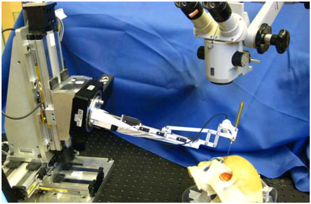
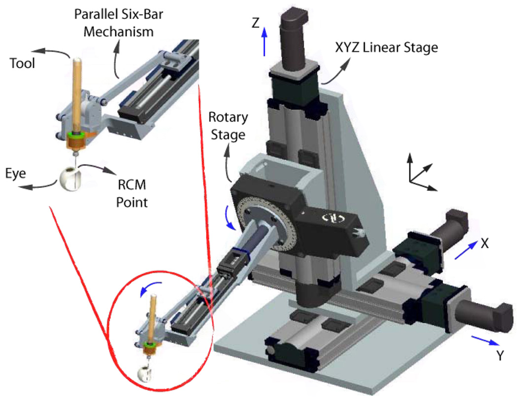
Eye Robot 2 (ER2) is an intermediate design towards a stable and fully capable microsurgery research platform for the evaluation and development of robot-assisted microsurgical procedures and devices (Fig. 1,2). Through extensive use of Eye Robot 1 (ER1), we have identified a number of limitations that are addressed in this new version.
Fig. 1.
Retinal surgery research platform.
Fig. 2.
CAD model of ER2, and close up view of its end effector.
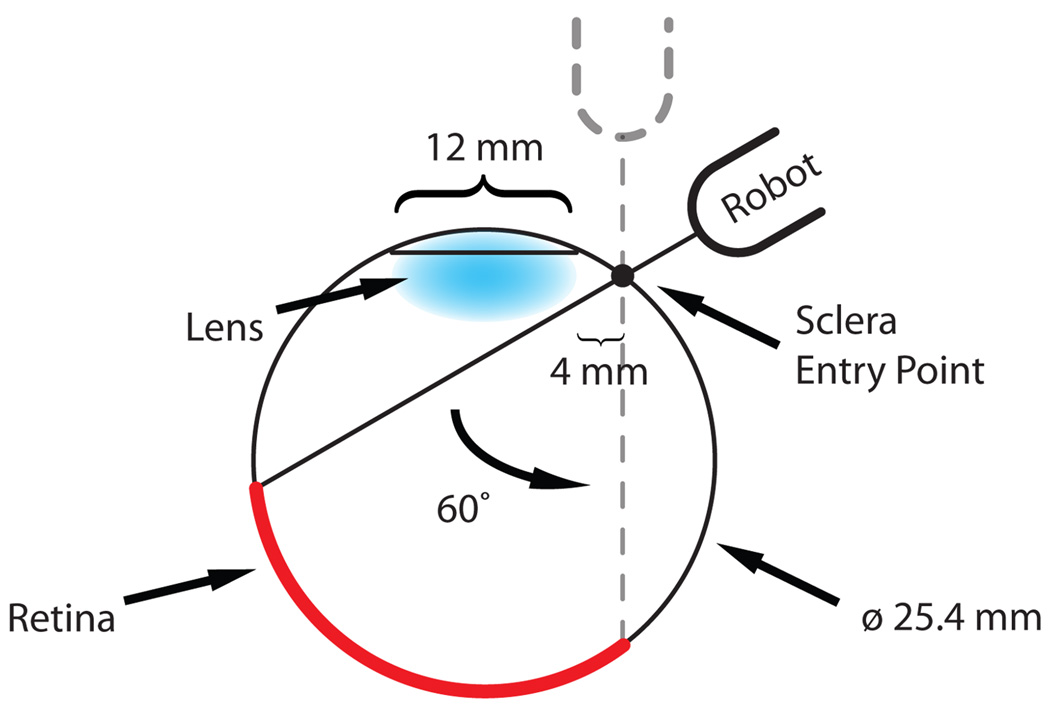
We increased the tool rotation range of the tilt axis to ±60° in order to cover a variety of user ergonomic preferences and extend the functionality of the robot for different tests and procedures. A geometric study of the eye (Fig. 3) reveals that the ±30° tool rotation limit of ER1 theoretically satisfies the necessary range of motion of the tool inside the eye. However, this required exact positioning of the robot relative to the skull, which is not always practical or even feasible.
Fig. 3.
Geometry study of tool motion through the sclera.
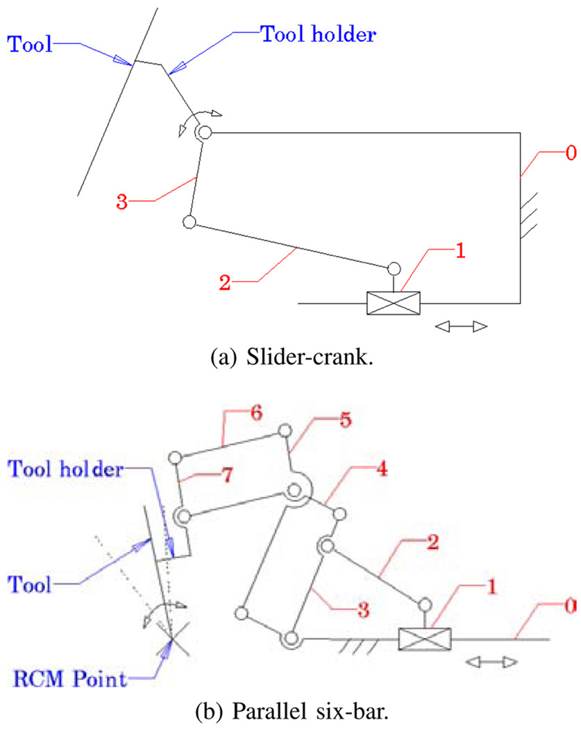
ER1 uses a slider-crank mechanism (Fig. 4a) for tilt rotation, which is a compact design with minimal connections and joints. It relies on software algorithm to programmatically constrain the tool axis to always intersect the sclerotomy opening on the eye [8]. Although this “Virtual RCM” was successful at constraining the motion, it was observed to introduce large concurrent joint velocities in the Cartesian stages. This is an undesirable behavior for a steady-hand robot. Here we have implemented a parallel six-bar mechanism (Fig. 4b) that mechanically provides the isocentric motion, which minimizes the translation of XYZ stages.
Fig. 4.
Tilting mechanisms of ER1 (a) and ER2 (b).
The lead-screws of ER1 were chosen to eliminate backlash, however through extensive use, we have found them to be unreliable, requiring regular maintenance and recalibration. The new design incorporates robust ball-screw linear stages that have high accuracy and precision. To further minimize the deflection error induced through user interaction, the extending carbon fiber arm was replaced by a more rigid tilt mechanism design with a rectangular profile.
A. Robot Components
The resulting robot manipulator consists of four subassemblies: 1) XYZ linear stages for translation; 2) a rotary stage for rolling 3) a tilting mechanism with a mechanical RCM and 4) a tool adaptor with a handle force sensor.
Parker Daedal 404XR linear stages (Parker Hannifin Corp., Rohnert Park, CA) with precise ball-screw are used to provide 100 mm travel along each axis with a bidirectional repeatability of 3 µm and positioning resolution of 1 µm. A Newport URS 100B rotary stage (Newport Corp., Irvine, CA) is used for rolling, with a resolution of 0.0005° and repeatability of 0.0001°. A THK KR15 linear stage (THK America Inc., Schaumburg, IL) with travel of 100 mm and repeatability of ±3 µm is used to provide tilting motion. The last active joint is a custom-designed RCM mechanism. A 6-DOF ATI Nano17 force/torque sensor (ATI Industrial Automation, Apex, NC) is mounted between the RCM and the tool handle. Assembly specifications are presented in Tab. I.
TABLE I.
ER2 ASSEMBLY SPECIFICATIONS.
| Specification | Value |
|---|---|
| XYZ motion | ±50 mm |
| roll/tilt motion | ±60° |
| tool tip speed during approach | 10 mm s−1 |
| insertion | 5 mm s−1 |
| manipulation | <1 mm s−1 |
| handle sensor force range/res | 0 N to 5 N (0.003 N) |
| handle sensor torque range/res | 0 N mm to 0.12 N mm (0.015 N mm) |
The new robot software is based on the CISST Surgical Assistant Workstation (SAW); a modular framework that provides multithreading, networking, data logging and standard device interfaces [15]. It enables rapid system prototyping by simplifying integration of new devices and smart tools into the systems.
B. Integrated Tip Force Sensor
ER2 is theoretically designed to achieve micron positioning accuracy. However, in practice, realizing this is greatly affected by the flexibility of the end effector, i.e. the surgical tool. The unknown interaction forces at the tool tip result in the deflection of the tool itself, which inherently affects the robot’s positioning performance. Measuring these forces directly allows us to compensate for this deformation. We can also integrate the real-time end-point sensing in intelligent control schemes with safety measures to minimize the risks associated with microsurgical procedures.
In related research, fiber Bragg grating (FBG) sensors were chosen to achieve high resolution force measurements at the tip of a long thin tube [16]. FBGs are optical sensors capable of detecting changes in force, pressure and acceleration, without interference from electrostatic, electromagnetic or radio frequency sources. The inherent design is theoretically temperature insensitive, but due to fabrication imperfections, temperature effects may be a factor. In such case it can be minimized by proper calibration and biasing.
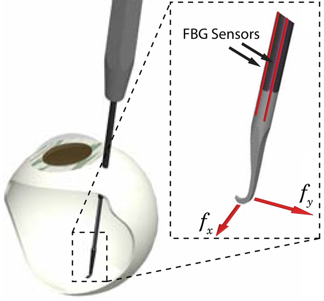
We have built a 2-axis hooked instrument (Fig. 5) presented in [9] that incorporates three optical fibers in a 0.5 mm diameter wire with a hooked tip. Based on the axial strain due to tool bending, the instrument senses forces at the tip in the transverse plane, with a sensitivity of 0.25 mN in the range of 0 mN to 60 mN.
Fig. 5.
Tool with FBG force sensors attached, inserted through a sclerotomy opening.
The instrument is rigidly attached to the handle of ER2 and is calibrated in order to transform it into the robot coordinates. Samples are acquired from the FBG interrogator at 2 kHz over a TCP/IP local network, and processed using software based on the same SAW framework.
III. METHODS
A. Tool Deflection Correction
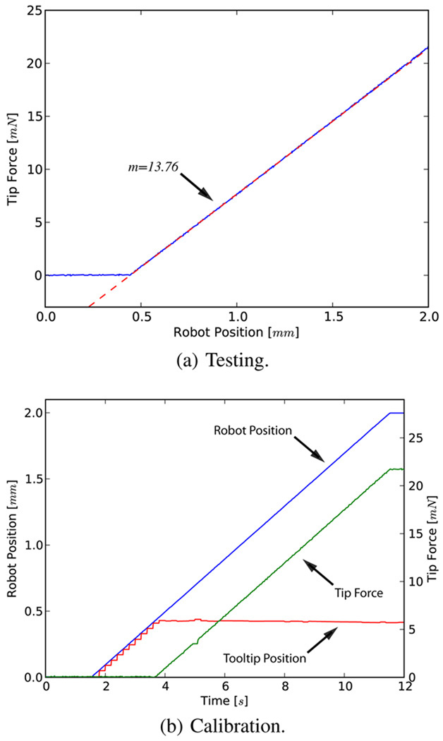
In order to address the issue of flexibility at the end effector we first characterized the deflection of the tool (Fig. 6a). The robot was translated 2 mm laterally, pushing the tool tip against a rigid surface. The corresponding reaction force is displayed in Fig. 6b.
Fig. 6.
Reaction force due to tool deflection for 2 mm travel. Note that the initial robot position is ~0.4 mm from the rigid surface.
The resulting response is linear and suggests a tool stiffness of 13.76 Nm−1. This constant (kt) is used to correct for the deformation in the following fashion.
| (1) |
| (2) |
| (3) |
where ft is the force at the tool tip and lt is the tool length. Since the amount of correction along the z-axis (Δz) is two orders of magnitude smaller than transverse plane correction we roughly approximate the tool as a rigid body pivoting around its base.
B. Constant Force Mode
This mode is used to command the robot to exert a desired constant force at the tool tip.
| (4) |
where the error between the desired force fd and tip force ft is scaled by a proportional gain kp and multiplied by the inverse Jacobian of the end effector to generate robot joint velocities.
C. Micro-force Guided Cooperative Control
Complications in vitreoretinal surgery may result from excess and/or incorrect application of forces to ocular tissue. Current practice requires the surgeon to keep operative forces low and safe through slow and steady maneuvering. The surgeon must also rely solely on visual feedback that complicates the problem, as it takes time to detect, assess and then react to the faint cues; a task especially difficult for novice surgeons.
Our cooperative control [8] was therefore “augmented” using the real-time information from the tool tip force sensor to gently guide the operator towards lower forces in a peeling task. The method can be analyzed in two main components as described below.
a) Global Force Limiting
This first layer of control enforces a global limit on the forces applied to the tissue at the robot tool tip. Setting a maximum force fmax, the limiting force flim on each axis would conventionally be defined as
| (5) |
However, this approach has the disadvantage of halting all motion when the tip force reaches the force limit, i.e. the operator has to back up the robot in order to apply a force in other directions. Distributing the limit with respect to the handle input forces
| (6) |
gives more freedom to the operator, allowing him/her to explore alternative directions (i.e. search for maneuvers that would generate lower tip forces) even when ft is at its limit. Considering the governing control law,
| (7) |
We apply the limit as follows;
| (8) |
Thus Cartesian velocity is proportionally scaled with respect to current tip force, where a virtual spring of length llim is used to ensure stability at the limit boundary.
b) Local Force Minimization
The second layer is to guide the operator in order to prevent reaching the limit in the first place. This is achieved by actively biasing the tool tip motion towards the direction of lower resistance. The ratio rt is used to update the operator input in the following fashion
| (9) |
where smin is the sensitivity of minimization that sets the ratio of the handle force to be locally minimized. Note that smin = 0% implies that the operator is not able to override the guided behavior.
Finally, for extra safety we also detect if either sensor is engaged, e.g. if the operator is not applying any force at the handle (< 0.1 N), the robot minimizes ft by “backing up”.
| (10) |
| Algorithm 1 Micro-force guided cooperative control. |
|---|
|
IV. EXPERIMENTS AND RESULTS
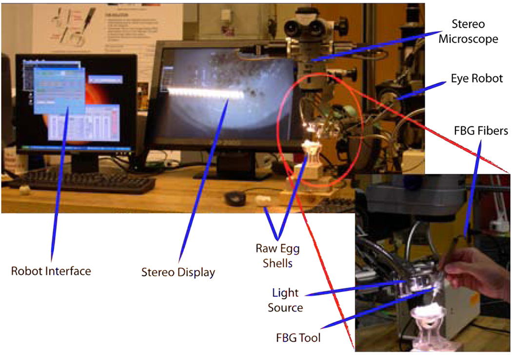
A series of experiments have been performed on the inner shell membrane of raw chicken eggs with the aim of identifying and controlling the forces associated with peeling operations (Fig. 8). We routinely use this membrane in our laboratory as a surrogate for an epiretinal membrane.
Fig. 8.
Setup for peeling experiments using raw eggs.
A. Tissue Force Characterization
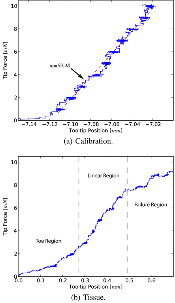
The first set of experiments was carried out to assess the capability of our system in characterizing tissue resistance forces through controlled motion and high resolution sensing. Attaching the surgical hook to the sample tissue we set a desired constant force and measured the translation with the corrected displacement of the tool tip. The applied force was increased by 1 mN with a 10 s delay between each increment. The system was first tested against a spring of known stiffness (Fig. 9a), where a 2.8% error was observed as compared to the calibrated value. Fig. 9b shows a sample force profile for the inner shell membrane. For these trials the surgical hook was first attached to the intact tissue and force was incrementally applied until failure. The membranes exhibit an average tearing force of 10 mN, after which, continuation of the tear is accomplished with lesser forces (~6 mN).
Fig. 9.
Force profiles for calibration and membrane peeling.
The characteristic curve obtained reveals a similar pattern to those seen in fibrous tissue tearing [17]. The toe region of the curve, the shape of which is due to the recruitment of collagen fibers, is a “safe region” from a surgical point of view and is followed by a predictable linear response. Yielding occurs as bonds begin to break, resulting in a sudden drop in resistive forces due to complete failure. In the surgical setting this marks the beginning of a membrane being peeled.
B. Micro-force Guided Cooperative Control
In the second set of experiments, we tested our control algorithm. A global limit of 7 mN was set, with a minimization sensitivity of 90%. An audio cue was also used to inform the operator when the limit was reached. We first tested the algorithm by stripping a piece of tape from a surface.
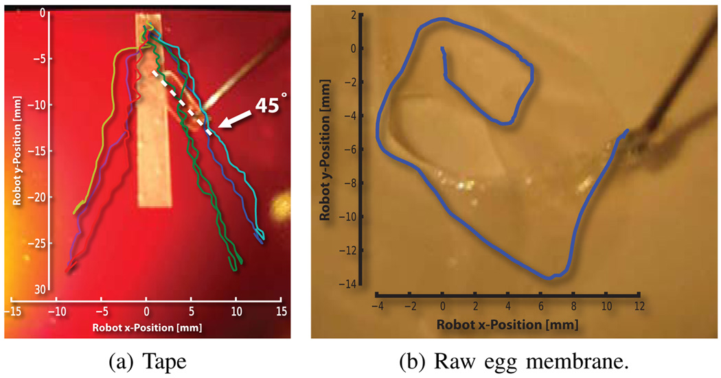
This work revealed the direction of minimum resistance for this phantom. The operator was naturally guided away from the centerline of the tape, following a gradient of force towards a local minimum resistance. Due to mechanical advantage, this corresponded to peeling at ~45° (Fig. 10a).
Fig. 10.
Diverging and circular robot trajectory overlays. Note that peeled section is half the distance traversed by the robot.
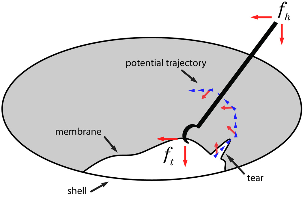
Repeating the experiments on the egg membrane, we observed a tendency to peel in circular trajectories (Fig. 10b). This behavior is consistent with the above trials with the added factor of continuously changing tear direction, i.e. tear follows the ~45° direction of force application (Fig. 7). Qualitatively, the algorithm was observed to magnify the perception of tip forces lateral to the operator’s desired motion.
Fig. 7.
Figure depicting a peeling process, with associated forces.
Upon reaching the force limit the operator explored around the boundary in search of points of lower resistance that would enable continuation of peel. This was achieved smoothly without requiring the operator to back up, as the limits on axes were redistributed based on operator’s application of handle force.
V. DISCUSSION AND CONCLUSION
We have designed, built and tested a platform for vitreoretinal surgery, on which we developed a novel cooperative control method that assists the operator in manipulating tissue within defined force limits. Using the system, we have identified basic tissue force profiles in egg inner shell membranes, which we then incorporated as input into our control algorithm.
The new generation system fulfills the function of simulating and evaluating microsurgical procedures to increase our understanding of the clinical requirements in microsurgical tasks. It also serves as a robot-assisted development test-bench for a multitude of smart tools, including but not limited to force sensing, optical coherence tomography, and spectroscopy modalities. Although we have incorporated lessons learned from the previous version, we are continuously improving ER2 towards a stable, fully capable and clinically compatible microsurgery assistance robot. We are redesigning the tool holder to accommodate quick exchange of a variety of instruments, and adding an encoder to the rotational passive joint of the tool. This would enable the use of more complex instruments like graspers, and track their pose in 6 DOF.
We have found that 2 DOF tool tip force sensing was adequate for the predefined manipulation tasks used in our controlled experimental setup. However, a 3 DOF force sensor will be required for interaction in less constrained maneuvers on more complex phantoms. The methods presented here can easily be extended to make use of the extra degree of sensing and expand their range of applications.
Our micro-force guided cooperative control method was successful in enforcing force limits, while assisting the operator in achieving the desired goal. According to our surgeon co-authors, the circular pattern obtained in egg membrane peeling resembled standard surgical peeling techniques they employ, e.g. capsulorhexis maneuver during opening of the anterior capsule for cataract surgery. Further assessment of this comparison could help us better understand the underlying principles of such surgical methods, eventually helping us to improve their performance.
The presented experiments with raw eggs demonstrate the potential capability of our platform for in-vivo analysis of tissue properties. Further information on tissue variation resulting from instantaneous reaction forces may be required to fully predict tissue behavior. These data will be fundamental to the design of intelligent robot control methods. The dynamic properties may help us to identify pathological signatures in target surgical tissue. More importantly such data can be used in training simulations for novice surgeons, especially to correlate the visual cues to quantifiable tissue behaviors.
Acknowledgments
This work was supported in part by the U.S. National Science Foundation under Cooperative Agreement ERC9731478, in part by the National Institutes of Health under BRP 1 R01 EB 007969-01 A1, and in part by Johns Hopkins internal funds.
REFERENCES
- 1.Gupta P, Jensen P, de Juan E. Surgical forces and tactile perception during retinal microsurgery. Medical Image Computing and Computer-Assisted Intervention (MICCAI) 1999:1218–1225. [Google Scholar]
- 2.Guthart G, Salisbury J.K J. The intuitive telesurgery system: overview and application. IEEE ICRA. 2000;vol. 1:618–621. [Google Scholar]
- 3.Nakano T, Sugita N, Ueta T, Tamaki Y, Mitsuishi M. A parallel robot to assist vitreoretinal surgery. International Journal of Computer Assisted Radiology and Surgery (IJCARS) 2009 Nov;vol. 4(no. 6):517–526. doi: 10.1007/s11548-009-0374-2. [DOI] [PubMed] [Google Scholar]
- 4.Wei W, Goldman R, Simaan N, Fine H, Chang S. Design and theoretical evaluation of micro-surgical manipulators for orbital manipulation and intraocular dexterity. IEEE ICRA. 2007 Apr;:3389–3395. [Google Scholar]
- 5.Riviere C, Ang WT, Khosla P. Toward active tremor canceling in handheld microsurgical instruments. IEEE ICRA. 2003 Oct;vol. 19(no. 5):793–800. [Google Scholar]
- 6.Tan U-X, Latt WT, Shee CY, Ang WT. Design and development of a low-cost flexure-based hand-held mechanism for micromanipulation. IEEE ICRA. 2009 May;:4350–4355. [Google Scholar]
- 7.Taylor R, Jensen P, Whitcomb L, Barnes A, Kumar R, Stoianovici D, Gupta P, Wang Z, deJuan E, Kavoussi L. A steady-hand robotic system for microsurgical augmentation. MICCAI. 1999:1031–1041. [Google Scholar]
- 8.Mitchell B, Koo J, Iordachita M, Kazanzides P, Kapoor A, Handa J, Hager G, Taylor R. Development and application of a new steady-hand manipulator for retinal surgery. IEEE ICRA. 2007 Apr;:623–629. [Google Scholar]
- 9.Iordachita I, Sun Z, Balicki M, Kang J, Phee S, Handa J, Gehlbach P, Taylor R. A sub-millimetric, 0.25 mn resolution fully integrated fiber-optic force-sensing tool for retinal microsurgery. International Journal of Computer Assisted Radiology and Surgery (IJCARS) 2009 Jun;vol. 4(no. 4):383–390. doi: 10.1007/s11548-009-0301-6. [DOI] [PMC free article] [PubMed] [Google Scholar]
- 10.Jagtap A, Riviere C. Applied force during vitreoretinal microsurgery with handheld instruments; IEEE International Conference on Engineering in Medicine and Biology Society (IEMBS); 2004. Sep, pp. 2771–2773. [DOI] [PubMed] [Google Scholar]
- 11.Berkelman P, Whitcomb L, Taylor R, Jensen P. A miniature microsurgical instrument tip force sensor for enhanced force feedback during robot-assisted manipulation. IEEE ICRA. 2003 Oct;vol. 19(no. 5):917–921. [Google Scholar]
- 12.Kumar R, Berkelman P, Gupta P, Barnes A, Jensen P, Whitcomb L, Taylor R. Preliminary experiments in cooperative human/robot force control for robot assisted microsurgical manipulation; IEEE International Conference on Robotics and Automation (ICRA); 2000. pp. 610–617. [Google Scholar]
- 13.Berkelman PJ, Rothbaum DL, Roy J, Lang S, Whitcomb LL, Hager GD, Jensen PS, Juan Ed, Taylor RH, Niparko JK. MICCAI. London, UK: Springer-Verlag; 2001. Performance evaluation of a cooperative manipulation microsurgical assistant robot applied to stapedotomy; pp. 1426–1429. [Google Scholar]
- 14.Fleming I, Balicki M, Koo J, Iordachita I, Mitchell B, Handa J, Hager G, Taylor R. Cooperative robot assistant for retinal microsurgery. MICCAI. 2008:543–550. doi: 10.1007/978-3-540-85990-1_65. [DOI] [PubMed] [Google Scholar]
- 15.Vagvolgyi B, DiMaio S, Deguet A, Kazanzides P, Kumar R, Hasser C, Taylor R. The Surgical Assistant Workstation: a software framework for telesurgical robotics research. MICCAI Workshop on Systems and Architectures for Computer Assisted Interventions. 2008 Sep; Midas Journal: http://hdl.handle.net/10380/1466. [Google Scholar]
- 16.Sun Z, Balicki M, Kang J, Handa J, Taylor R, Iordachita I. Development and preliminary data of novel integrated optical microforce sensing tools for retinal microsurgery. IEEE ICRA. 2009 May;:1897–1902. [Google Scholar]
- 17.Gentleman E, Lay AN, Dickerson DA, Nauman EA, Livesay GA, Dee KC. Mechanical characterization of collagen fibers and scaffolds for tissue engineering. Biomaterials. 2003;vol. 24(no. 21):3805–3813. doi: 10.1016/s0142-9612(03)00206-0. [DOI] [PubMed] [Google Scholar]


