Abstract
We demonstrate a new approach to utilize copper(I) iodide coordination complexes as emissive layers in organic light-emitting diodes (OLEDs), by in situ codeposition of copper(I) iodide and 3,5-bis(carbazol-9-yl)pyridine (mCPy). With a simple three-layer device structure, pure green electroluminescence at 530 nm from a copper(I) complex was observed. Maximum luminance and external quantum efficiency (EQE) of 9700 cd/m2 and 4.4% have been achieved, respectively. The luminescent species has been identified as [CuI(mCPy)2]2 based on photophysical studies of model complexes and X-ray absorption spectroscopy (XAS).
Tremendous improvements in organic light-emitting diodes (OLEDs) have been achieved using phosphorescent emissive iridium-based complexes.1–4 Unfortunately, iridium is low in natural abundance, so there has been an increasing interest in luminescent copper(I) complexes5–8 for use in high efficiency OLEDs. However, since most copper(I) complexes are unstable to sublimation,9 and hence not amenable to the vacuum deposition methods typically used to fabricate OLEDs, few devices containing such emitters have been reported.10–15
Among luminescent copper(I) complexes, those based on copper(I) iodide (CuI) are well known for their structural diversity, rich photophysical behavior, and high luminance efficiency.16–18 A wide range of structure motifs have been prepared by combining CuI and pyridine-based ligands in different ratios.19–22 Excited states in the resulting complexes have been proposed to be halide-to-ligand charge transfer (XLCT), metal-to-ligand charge transfer (MLCT), and/or halide-to-metal charge transfer (XMCT), based on experimental and computational studies.16, 23 Generally, CuI-based complexes, especially with pyridine-based ligands are highly emissive at room temperature regardless of structure and nature of the excited state. However, the application of these complexes in OLEDs has not been demonstrated, due to the aforementioned difficulties with sublimation, as well as their poor solubility or stability in solution. In this paper, we demonstrate that codeposition of CuI and 3,5-bis(carbazol-9-yl)pyridine (mCPy, Figure 1) is an efficient way to utilize CuI complexes as emissive materials in OLEDs. Devices made using CuI:mCPy films exhibit pure green electroluminescence (EL) from a copper(I) emitting species. The chemical composition of the luminescent species in the codeposited film has been deduced by studies of model complexes and X-ray absorption spectroscopy (XAS) and determined to be primarily [CuI(mCPy)2]2.
Figure 1.
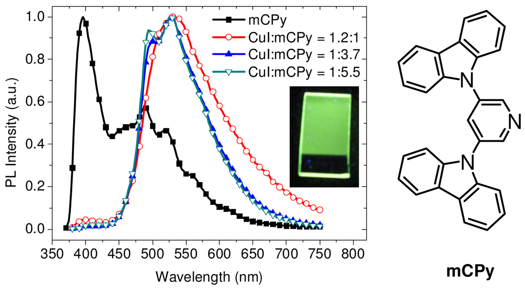
Left: PL spectra of neat mCPy film at 77 K and CuI:mCPy films at room temperature with excitation wavelength of 350 nm. Insert: photo of CuI:mCPy film under UV light (365 nm). Right: Chemical structure of mCPy.
Figure 1 shows the photoluminescence (PL) spectra of a series of CuI:mCPy films made by codepositing CuI and mCPy in different molar ratios from two separate heating sources in a vacuum chamber. For comparison, the PL spectrum of a neat mCPy film at 77 K is also shown in Figure 1. The spectrum for the neat mCPy film consists of an overlapping fluorescent band at 400 nm (biexponential decay, τ = 10.9 (17%) and 2.0 (83%) ns) and phosphorescent band at 500 nm (monoexponential decay, τ = 0.48 s). PL was observed for CuI:mCPy codeposited films over a wide range of molar ratios, with quantum yields as high as 64%. PL spectra from CuI:mCPy films are dominated by a band centered near 520 nm and have decay lifetimes (Table 1) that differ markedly from the mCPy film, implying the formation of phosphorescent copper(I) complexes. The emission spectra of CuI:mCPy films sometimes show an additional feature at 495 nm (Figure 1). While the shoulder at 495 nm is coincident with the phosphorescent band of neat mCPy, other data are inconsistent with emission from the neat ligand. Transient measurements at the two wavelengths give the same biexponential lifetimes listed in Table 1 for each composition. In addition, the CuI:mCPy film has identical PL spectra at 298 K and 77 K. If the band at 495 nm were caused by emission from neat mCPy, one would expect it to be more prominent at the lower temperature. Thus, the 495 nm feature is likely due to a second copper(I) complex at low concentration.
Table 1.
Photophysical data of codeposited CuI:mCPy films.
| CuI:mCPy (molar ratio) |
λem (nm) |
PLQYa (%) |
Lifetimeb(percentage) (µs, %) |
|---|---|---|---|
| 1.8 : 1.0 | - | 0 | - |
| 1.2 : 1.0 | 532 | 8 | 0.5 (32), 3.0 (68) |
| 1.0 : 2.3 | 496, 528 | 48 | 3.1 (28), 10.1 (72) |
| 1.0 : 2.6 | 502, 528 | 62 | 4.4 (35), 12.8 (65) |
| 1.0 : 3.7 | 500, 528 | 63 | 3.4 (21), 11.5 (79) |
| 1.0 : 5.5 | 495, 528 | 64 | 3.5 (28), 11.6 (72) |
PL quantum yield, and
Emission lifetimes were measured at 520 nm with excitation energy of 331 nm.
To verify that CuI:mCPy complexes are responsible for the luminescence from codeposited films, we prepared a film by codepositing CuI and 1,3-bis(carbazol-9-yl)benzene (mCP), which lacks the coordinating pyridyl group in mCPy. The emission spectrum of the CuI:mCP film is identical to that of mCP (λmax = 425 nm), indicating that pyridine coordination is required to form the emissive species in the CuI:mCPy film.
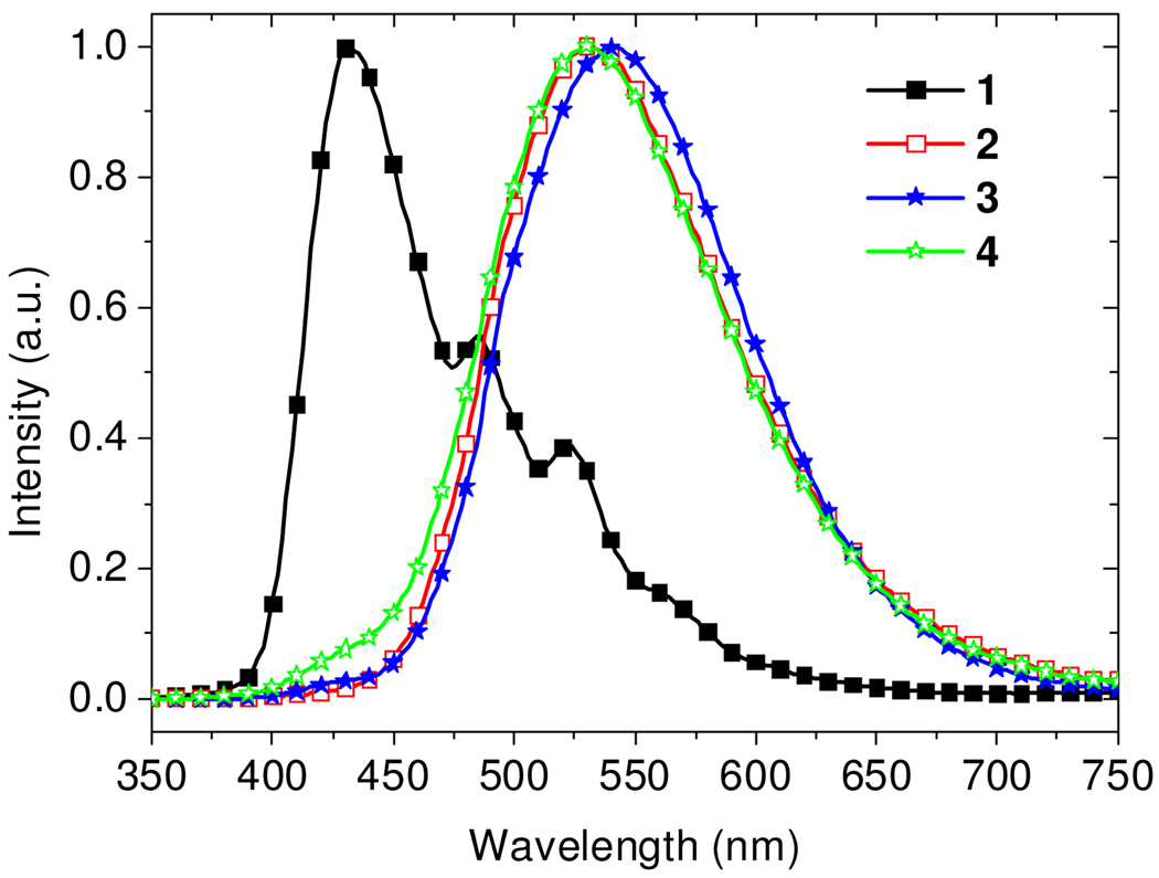
CuI:mCPy films were used to fabricate four OLEDs (ITO/NPD (25 nm)/CuI:mCPy (20 nm)/BCP (40 nm)/LiF (1 nm)/Al (100 nm)) where the molar ratio of the CuI:mCPy films was varied, i.e. 0:1 (device 1), 1:4 (device 2), 1:6 (device 3) and 1:10 (device 4); NPD = N,N'-bis(naphthalen-1-yl)-N,N'-bis(phenyl)-benzidine, BCP = bathocuproine. Figure 2 shows electroluminescence (EL) spectra of the devices at 8 V. Emission from devices 2–4 is significantly different from that of device 1, indicating that the luminescence arises from a CuI:mCPy complex, consistent with the aforementioned PL study. EL solely from CuI:mCPy was observed in device 2 under all applied voltages. Devices 3 and 4, with higher mCPy concentrations, exhibited a very small emissive contribution from mCPy at high applied voltages (Figure S5). Among the OLEDs 1–4, device 4 with highest mCPy ratio (CuI:mCPy = 1:10) shows the highest external quantum efficiency (EQE = 3.2%).
Figure 2.
EL spectra of devices ITO/ NPD/ EML/ BCP/ LiF/ Al at 8V, where the EML is neat mCPy (device 1), CuI:mCPy (1:4, device 2), CuI:mCPy (1:6, device 3), or CuI:mCPy (1:10, device 4).
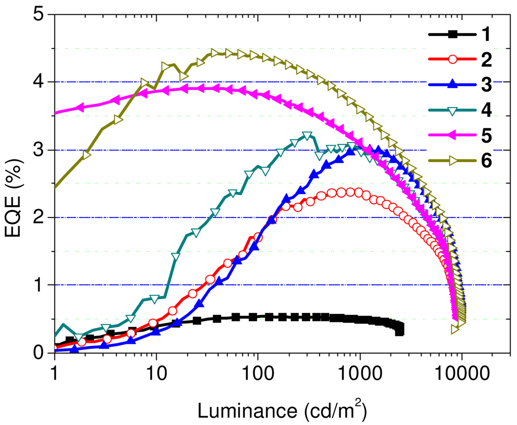
Two more devices were fabricated with an Alq3 electron transport layer (ETL). The structure is ITO/ NPD (25 nm)/ CuI:mCPy (1:5, 20 nm)/ BCP (x nm)/ Alq3 (30 nm)/ LiF (1 nm)/ Al (100 nm) (Alq3 = tris(8-hydroxy-quinolinato)aluminum), where the thickness of BCP layer was either x = 10 nm (device 5) or x = 0 nm (device 6). The two devices have emission spectra similar to that of device 3, indicating that hole–electron combination occurs within the CuI:mCPy layer and that EL arises from a CuI:mCPy complex. As shown in Figure 3 and Table 2, device 6 gives the highest EQE (4.4%), power efficiency (PE = 10.2 lm/W) and current efficiency (CE = 13.8 cd/A). Device 6 with Alq3 as the sole ETL gives a higher efficiency than devices with BCP, i.e. 2–5, likely as a result of better balance in charge injection/transport. Moreover, the increase in efficiency suggests that further improvement in performance can be achieved by optimizing the device configuration.
Figure 3.
EQE-luminance curves of devices 1–6, where the EML is CuI:mCPy (1:5) for both devices 5 and 6.
Table 2.
Performance of devices 1–6
| device |
Vona (V) |
Lmax (cd/m2) |
EQEmax (%) |
PEmax (lm/W) |
CEmax (cd/A) |
|---|---|---|---|---|---|
| 1 | 6.4 | 2500 | 0.54 | 0.28 | 0.86 |
| 2 | 3.6 | 8800 | 2.4 | 3.8 | 7.4 |
| 3 | 3.5 | 9900 | 3.0 | 4.9 | 9.7 |
| 4 | 3.7 | 9100 | 3.2 | 5.3 | 9.8 |
| 5 | 3.5 | 9100 | 3.9 | 10.3 | 11.7 |
| 6 | 3.6 | 9700 | 4.4 | 10.2 | 13.8 |
Von is the voltage required to reach a brightness of 1 cd/m2
Our initial lifetime measurements on CuI:mCPy-based OLEDs are encouraging. In this study we monitored the light output of device 6 under vacuum (150 mTorr), while driving the device at a current density of 20 mA/cm2 (brightness = 2100 cd/m2). The half-life for the device under these conditions was 21 hours, corresponding to 440 hours at 100 cd/m2. While this is well below the lifetimes reported for optimized OLEDs, it is a factor of five longer than an analogous device with the CuI:mCPy emissive layer replaced with a 20 nm layer of Ir(ppy)3:mCPy (10 wt%, Ir(ppy)3 = fac-tris(2-phenylpyridine)iridium). When this Ir(ppy)3 based device was driven under the same conditions, a projected half-life at 100 cd/m2 of 75 hours was observed. This indicates that the CuI:mCPy emissive layer is quite stable and promising for OLED applications.
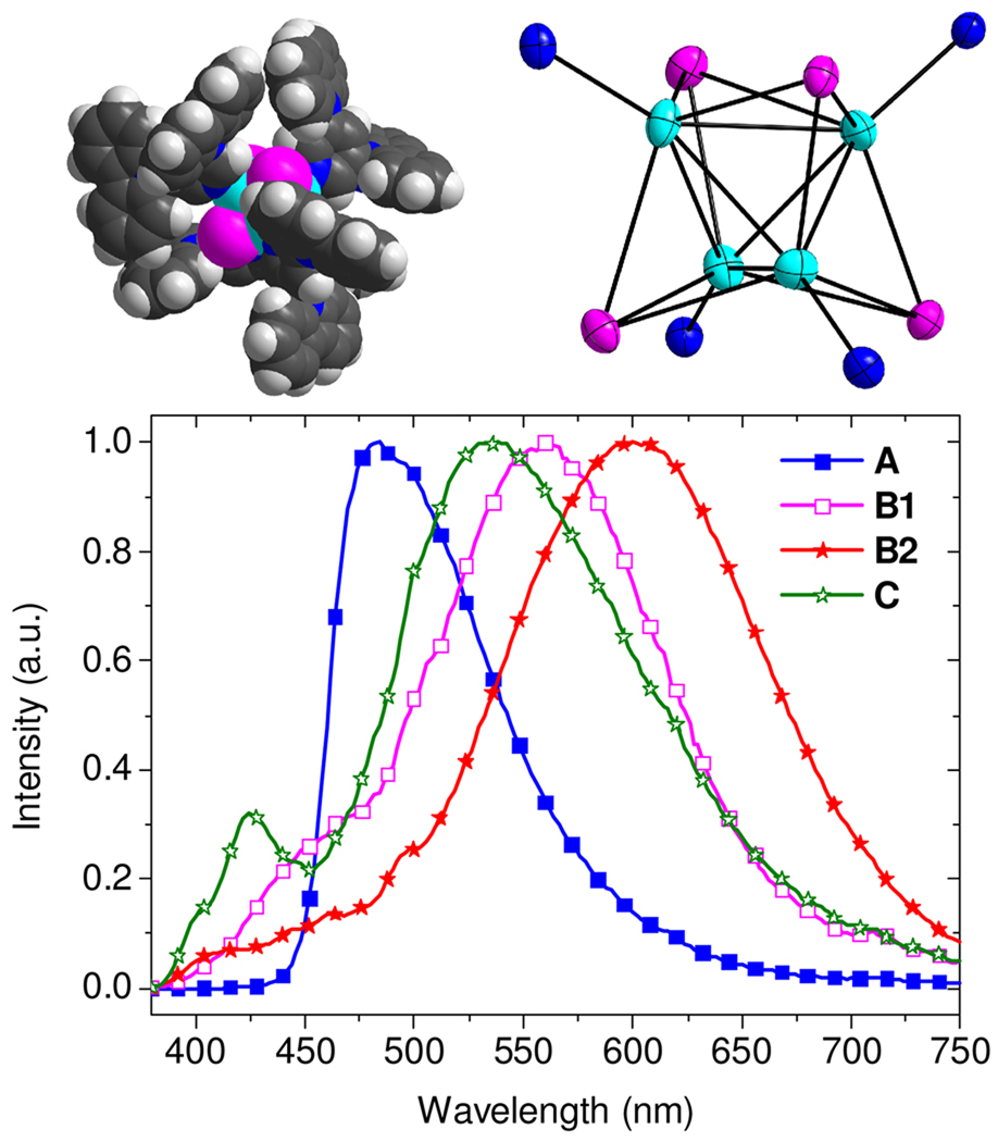
Previous work has shown that the three main products from reactions of CuI and pyridine, that is, [CuI(py)]∞, [CuI(py)2]2, and [CuI(py)]4 (py = pyridine), show blue, green, and orange emission, respectively, in the solid state at room temperature.16 We have prepared several related complexes to model the luminescent species in the codeposited CuI:mCPy film. [CuI(mCPy)]∞ (model A) was synthesized via the reported method for [CuI(py)]∞ 16 and characterized by elemental analysis and emission spectroscopy. The complex gives blue emission with maximum wavelength around 480 nm (Figure 4) and PLQY of 64% in the solid state at room temperature. The emission exhibited a slight red shift as the temperature was decreased to 77 K (λmax = 486, 508 nm). The PL lifetimes measured at 480 nm were found to be 3.0 and 16.8 µs at room temperature and 77 K, respectively.
Figure 4.
Upper left: Space-filling drawing of [CuI(mCPy)]4·3CH2Cl2 (Model B1) from crystal coordinates. Upper right: ORTEP structure (50%) of the Cu4I4 core of B1 with only the coordinating N atoms of the mCPy ligands shown. Lower: PL spectra of [CuI(mCPy)]∞ (model A), B1, [CuI(mCPy)]4 (model B2), and ground CuI with mCPy (model C) with excitation wavelength of 350 nm.
Another model complex, [CuI(mCPy)]4·3CH2Cl2 (model B1), was synthesized by mixing CuI and mCPy in CH2Cl2, and characterized by single crystal X-ray diffraction. The structure consists of Cu4 tetrahedra with iodides capping all four faces and the mCPy pyridyl ligands at the apexes (Figure 4). This structure is very similar to that of [CuI(py)]4.20 The model B1 gives a primary emission band around 560 nm with decay lifetime of 2.1 µs at room temperature. Exposure of crystalline B1 to vacuum results in loss of CH2Cl2, forming model B2, [CuI(mCPy)]4, with dominating emission at 620 nm and decay lifetime of 7.3 µs. Both models B1 and B2 show clear luminescent thermochromism with strong blue emission (λmax = 500 nm) at 77 K and decay lifetimes of ~30 µs, similar to many reported (CuIL)4 clusters.16,24,25 In contrast, the codeposited films show identical spectra at 298 K and 77 K.
It was found that an amorphous material (model C), prepared by simple grinding of CuI with mCPy at a molar ratio of 1:4, gives emission centered at 530 nm with decay lifetimes of 4.0 (37%) and 11.0 (63%) µs, quite similar to our deposited films. No complex could be isolated on dissolution of model C, since it transforms to polymeric [CuI(mCPy)]∞ in CH3CN and tetrameric [CuI(mCPy)]4 in CH2Cl2. Moreover, grinding either [CuI(mCPy)]∞ or [CuI(mCPy)]4 with or without mCPy leads to a material that has photophysical properties similar to that of the codeposited CuI:mCPy film, although the most efficient emission is observed with added mCPy.
To characterize the structure of the luminescent species in codeposited films, we have used X-ray absorption spectroscopy (XAS). In order to generate sufficient material for XAS study, approximately 2 µm CuI:mCPy films (ratio = 1:2.5) were deposited on five four-inch Si wafers and scraped off to give a 40 mg powdered sample (model D). The molar ratio was confirmed by elemental analysis. Model D shows identical photophysical properties to the codeposited films used for photophysical and EL studies. Details of sample preparation, characterization, data collection and analysis for XAS are given in the Supporting Information. Investigation of the XANES pre-edge region confirms the presence of only monovalent copper in the sample. The XANES spectrum was compared with those of known 2-, 3-, and 4-coordinate model complexes [Cu(xypz)]2(BF4)2 (xypz = bis(3,5-dimethylpyrazoyl)-m-xylene), [(C6H5)4P]2[Cu(SC6H5)3], and [Cu(py)4]ClO4, respectively (Figure S10).26 The intensity of the peak at ~8984.5 eV, which is characteristic of 1s→4p transitions in Cu(I) species, precludes the possibility of 2-coordinate Cu(I) in the sample. The energy of the 3-coordinate Cu(I) model complex closely matches that of the Cu(I) in the film. However, the energy of the 1s→4p transition can decrease with iodide ligation due to greater electron donation ability of iodide over that of the N/S based ligands of the model complexes, thus resulting in a lower Zeff. In addition, decreased antibonding of the halide orbitals with Cu(I) 4p orbitals compared with the N/S-ligand reference complexes can also contribute to a shift to lower energy. Thus, the data are also consistent with the presence of a 4-coordinate Cu(I) species in the CuI:mCPy film (model D).
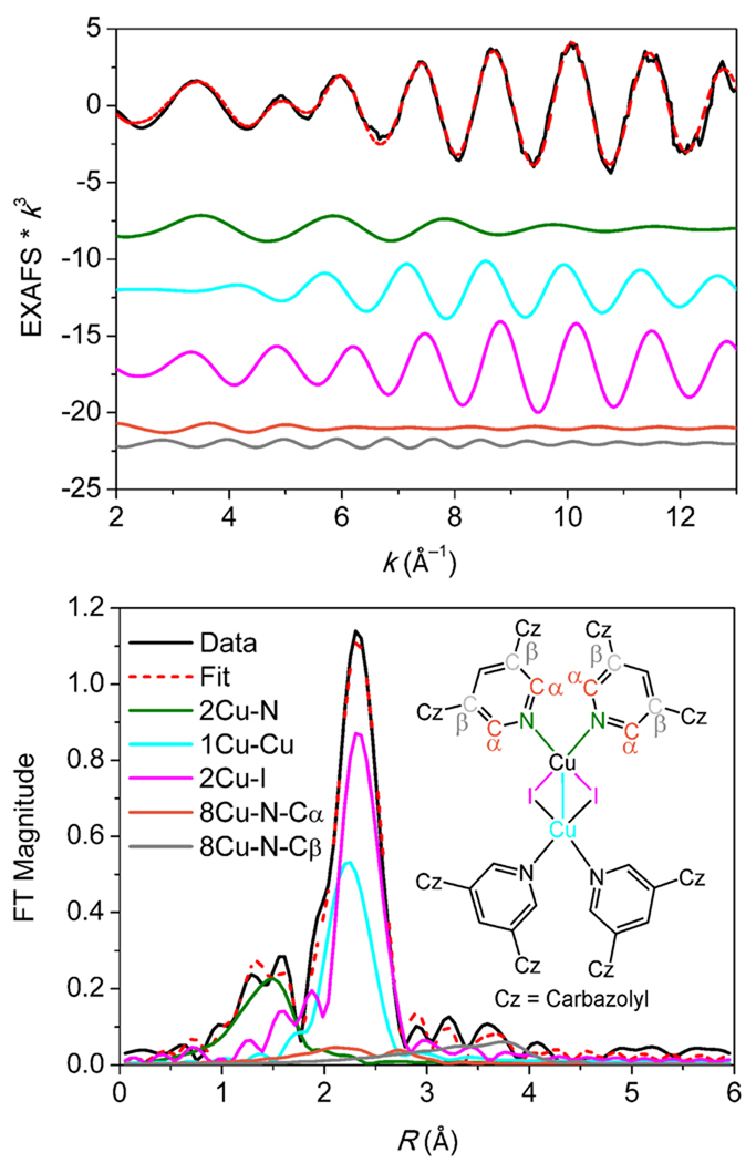
The k3-weighted Cu K-edge EXAFS data and Fourier transform (FT) are shown in Figure 5 and the EXAFS fit parameters are given in Table 3. Also in Table 3 are EXAFS fit parameters for polymeric model complex A and related parameters, derived from crystallographic coordinates, for model B1 and [CuI(pyCN)2]2 27 (pyCN = 3-cyanopyridine, model E) for comparison. The combination of 1 Cu–Cu and 2 Cu–I paths around 2.6 Å gives the best fit to the data. The distance and σ2-parameter for the two paths are strongly correlated. On the other hand, a poor fit to the data is found when either of these paths is excluded or when any one of the two paths, in the absence of the other, is split into two. Other coordination numbers between 1 and 4 for Cu–Cu and Cu–I can be excluded based on a poorer fit factor, F, and/or higher σ2. A Cu–N path at 2.02 Å is also necessary. A slight, albeit insignificant, improvement in the fit is observed using a 2 Cu–N, rather than a 1 Cu–N path.
Figure 5.
Cu K-edge EXAFS data to k = 13.4 Å−1 (top) and non-phase-shift-corrected Fourier transform (bottom) of CuI:mCPy codeposited film species (model D, CuI:mCPy = 1:2.5). Insert: chemical structure of [CuI(mCPy)2]2. Phase shift in the first shell is ~0.4 Å. Data, fit, and deconvoluted waves shown.
Table 3.
EXAFS least-squares fitting results for k = 2–13.4 Å−1 for CuI:mCPy codeposited film species (model D), as well as key parameters for model complexes [CuI(mCPy)]∞ (model A), [CuI(mCPy)]4·3CH2Cl2 (model B1), and [CuI(pyCN)2]2 (model E).
| Model | Path | Cu-Cu | Cu-I | Cu-N | Cu- N-Cα |
Cu-N- Cβ |
|
|---|---|---|---|---|---|---|---|
|
D film |
Coord. R(Å)a σ2(Å2)b |
1 2.60 755 |
2 2.63 570 |
2 2.02 1108 |
8 3.23 663 |
8 4.34 756 |
|
|
Ac (CuIL)∞ |
 |
Coord. R(Å) |
2 2.70 |
3 2.63 |
1 2.05 |
||
|
B1d (CuIL)4 |
See Figure 4 upper right |
Coord. R(Å) |
3 2.65 |
3 2.63 |
1 2.03 |
||
|
Ed (CuIL2)2 |
Coord. R(Å) |
1 2.66 |
2 2.65 |
2 2.08 |
|||
ΔE0(eV) = −13.68 for the EXAFS fit of D, while the goodness of fit, Fnormalized, defined by Σ[(χobsd – χcalcd)2k6]/Σ[(χobsd)2k6]0.5 is 0.117.
The estimated standard deviations in R for each fit is ±0.02 Å.
The σ2 values have been multiplied by 105.
The EXAFS fit of A is shown in the Supporting Information.
Parameters for B1 and E have been taken from their respective crystal structures.
Analysis of the EXAFS and FT data enable us to distinguish the major Cu(I) species present in the CuI:mCPy film. The data for Model D and [CuI(mCPy)]∞ polymer (Figures S11–13) show major differences, confirming that the CuI:mCPy film and polymer are comprised of different species. A complex related to the [CuI(mCPy)]4 tetramer (model B1) can also be eliminated as a possibility upon comparing the Cu–Cu and Cu–I coordination numbers in Table 3. The structural parameters found in Model D closely match those reported in the literature for [CuI(pyCN)2]2 (model E).27 Thus, on the basis of both the luminescent spectra and XAS studies, the emitting species in CuI:mCPy thin films is most likely a dimeric complex, [CuI(mCPy)2]2, illustrated in the insert to Figure 5, and small variable amounts of [CuI(mCPy)]∞, in low enough concentration that it does not contribute significantly to the XAS.
The codeposition of mCPy with CuBr and CuCl was also examined. Both CuBr and CuCl react with mCPy to form luminescent films. However, neither halide material shows a luminescent efficiency comparable to the CuI-based materials. Films made using CuBr display an emission peak at 550 nm (τ = 6.7 µs) with maximum PLQY of 37%. The CuCl-based film has a red-shifted emission peak at 570 nm (τ = 3.1 µs), and a lower PLQY of 14%. The red-shifted emission spectra and decreased PLQY are consistent with the low ligand field strengths of the Br and Cl anions and the expected reduction in the spin-orbit coupling for the lower Z halogens.
We have also examined thin films prepared by codeposition of CuI and common OLED materials namely 1,3,5-tris(N-phenylbenzimidazole-2-yl)benzene (TPBi) and 2-(4-biphenylyl)-5-(4-tert-butylphenyl)-1,3,4-oxadiazole (PBD). Emission form both TPBi- and PBD-based films give substantial components for the organic materials themselves as well as a CuI complex (Figure S15) and only moderate PLQYs (~17% and 14%, respectively). The low efficiency and ligand contamination of the spectra are likely due to the fact that both TPBi and PBD are poor ligands for copper, leading to incomplete formation of the emissive Cu(I) complex.
In summary, we have demonstrated that copper(I) iodide coordination complexes can be formed in situ by codeposition of CuI and ligand, leading to efficient OLEDs containing copper(I) complexes. The ligand material in this case serves a dual role as both a ligand for forming the emissive complex and as a host matrix for the formed emitter. While complex formation occurs for a number of materials, care must be taken in the design of the organic material to ensure that it is a good ligand for copper coordination. This new approach may be easily extended to other ligands to generate functional layers for use in organic optoelectronic devices.
Supplementary Material
Acknowledgments
We gratefully acknowledge financial support of this work from Universal Display Corporation and Center for Energy Nanoscience, an Energy Frontier Research Center funded by the U.S. Department of Energy, Office of Science, Office of Basic Energy Sciences (DE-SC0001011). Portions of this research were carried out at the Stanford Synchrotron Radiation Lightsource (SSRL). The SSRL Structural Molecular Biology Program is supported by the DOE Office of Biological and Environmental Research, and by the National Institutes of Health (NIH), National Center for Research Resources (NCRR), Biomedical Technology Program (P41RR001209). This study was supported in part by the NCRR (Grant Number 5 P41 RR001209), a component of the NIH.
Footnotes
Supporting Information Available: Experimental details; PL spectra of mCPy film and mCPy in 2-MeTHF at room temperature and 77 K; Decay lifetimes of codeposited CuI:mCPy film measured at various wavelengths; PL spectra of codeposited CuI:mCPy film at room temperature and 77 K; PL spectra of mCP and codeposited CuI:mCP films; EL spectra of devices 2 and 3 at different applied voltages; Current density-voltage curves of devices 1–6; PL spectra of models A, B1, B2, and D at room temperature and 77 K; The XANES comparison between codeposited CuI:mCPy powder sample with those of known 2-, 3-, and 4-coordinate Cu(I) complexes, as well as the EXAFS fit of model A; PL spectra of codeposited CuBr:mCPy, CuCl:mCPy, CuI:TPBi, and CuI:PBD films, and CIF file for the crystal [CuI(mCPy)]4·3CH2Cl2. This material is available free of charge via the internet at http://pubs.acs.org.
References
- 1.Baldo MA, Lamansky S, Burrows PE, Thompson ME, Forrest SR. Appl. Phys. Lett. 1999;75:4–6. [Google Scholar]
- 2.Lamansky S, Djurovich PI, Murphy D, Abdel-Razzaq F, Lee HE, Adachi C, Burrows PE, Forrest SR, Thompson ME. J. Am. Chem. Soc. 2001;123:4304–4312. doi: 10.1021/ja003693s. [DOI] [PubMed] [Google Scholar]
- 3.Djurovich PI, Thompson ME. Chapter 3. In: Yersin H, editor. Highly Efficient OLEDs with Phosphorescent Materials. Berlin: Wiley-VCH; 2007. pp. 131–161. [Google Scholar]
- 4.Thompson ME, Djurovich PI, Barlow S, Marder SR. In: Comprehensive Organmetallic Chemistry. O’Hare D, editor. Vol. 12. Oxford: Elsevier; 2007. pp. 101–194. [Google Scholar]
- 5.Ford PC, Cariati E, Bourassa J. Chem. Rev. 1999;99:3625–3647. doi: 10.1021/cr960109i. [DOI] [PubMed] [Google Scholar]
- 6.Armaroli N, Accorsi G, Cardinali F, Listorti A. Top. Curr. Chem. 2007;280:69–115. [Google Scholar]
- 7.Scaltrito DV, Thompson DW, O'Callaghan JA, Meyer GJ. Coord. Chem. Rev. 2000;208:243–266. [Google Scholar]
- 8.McMillin DR, McNett KM. Chem. Rev. 1998;98:1201–1219. doi: 10.1021/cr9601167. [DOI] [PubMed] [Google Scholar]
- 9.Manbeck GF, Brennessel WW, Evans CM, Eisenberg R. Inorg. Chem. 2010;49:2834–2843. doi: 10.1021/ic902236n. [DOI] [PubMed] [Google Scholar]
- 10.Zhang QS, Zhou QG, Cheng YX, Wang LX, Ma DG, Jing XB, Wang FS. Adv. Mater. 2004;16:432–436. [Google Scholar]
- 11.Che GB, Su ZS, Li WL, Chu B, Li MT, Hu ZZ, Zhang ZQ. Appl. Phys. Lett. 2006;89 103511. [Google Scholar]
- 12.Su ZS, Che GB, Li WL, Su WM, Li MT, Chu B, Li B, Zhang ZQ, Hu ZZ. Appl. Phys. Lett. 2006;88 213508. [Google Scholar]
- 13.Tsuboyama A, Kuge K, Furugori M, Okada S, Hoshino M, Ueno K. Inorg. Chem. 2007;46:1992–2001. doi: 10.1021/ic0608086. [DOI] [PubMed] [Google Scholar]
- 14.Deaton JC, Switalski SC, Kondakov DY, Young RH, Pawlik TD, Giesen DJ, Harkins SB, Miller AJM, Mickenberg SF, Peters JC. J. Am. Chem. Soc. 2010;132:9499–9508. doi: 10.1021/ja1004575. [DOI] [PubMed] [Google Scholar]
- 15.Armaroli N, Accorsi G, Holler M, Moudam O, Nierengarten JF, Zhou Z, Wegh RT, Welter R. Adv. Mater. 2006;18:1313–1316. [Google Scholar]
- 16.Kyle KR, Ryu CK, Dibenedetto JA, Ford PC. J. Am. Chem. Soc. 1991;113:2954–2965. [Google Scholar]
- 17.Kim TH, Shin YW, Jung JH, Kim JS, Kim J. Angew. Chem. Int. Ed. 2008;47:685–688. doi: 10.1002/anie.200704349. [DOI] [PubMed] [Google Scholar]
- 18.Araki H, Tsuge K, Sasaki Y, Ishizaka S, Kitamura N. Inorg. Chem. 2005;44:9667–9675. doi: 10.1021/ic0510359. [DOI] [PubMed] [Google Scholar]
- 19.Dyason JC, Healy PC, Pakawatchai C, Patrick VA, White AH. Inorg. Chem. 1985;24:1957–1960. [Google Scholar]
- 20.Raston CL, White AH. J. Chem. Soc., Dalton Trans. 1976:2153–2156. [Google Scholar]
- 21.Rath NP, Maxwell JL, Holt EM. J. Chem. Soc., Dalton Trans. 1986:2449–2453. [Google Scholar]
- 22.Eitel E, Oelkrug D, Hiller W, Strahle J. Z. Naturforsch. B. 1980;35:1247–1253. [Google Scholar]
- 23.De Angelis F, Fantacci S, Sgamellotti A, Cariati E, Ugo R, Ford PC. Inorg. Chem. 2006;45:10576–10584. doi: 10.1021/ic061147f. [DOI] [PubMed] [Google Scholar]
- 24.Perruchas S, Le Goff XF, Maron S, Maurin I, Guillen F, Garcia A, Gacoin T, Boilot JP. J. Am. Chem. Soc. 2010;132:10967–10969. doi: 10.1021/ja103431d. [DOI] [PubMed] [Google Scholar]
- 25.Tard C, Perruchas S, Maron S, Le Goff XF, Guillen F, Garcia A, Vigneron J, Etcheberry A, Gacoin T, Boilot JP. Chem. Mater. 2008;20:7010–7016. [Google Scholar]
- 26.Kau LS, Spirasolomon DJ, Pennerhahn JE, Hodgson KO, Solomon EI. J. Am. Chem. Soc. 1987;109:6433–6442. [Google Scholar]
- 27.Huang XC, Ng SW. Acta Cryst. 2004;60:m1055–m1056. [Google Scholar]
Associated Data
This section collects any data citations, data availability statements, or supplementary materials included in this article.


