

Abstract
A fundamental question in developmental biology is how spatial patterns are self-organized from homogeneous structures. In 1952, Turing proposed the reaction-diffusion model in order to explain this issue. Experimental evidence of reaction-diffusion patterns in living organisms was first provided by the pigmentation pattern on the skin of fishes in 1995. However, whether or not this mechanism plays an essential role in developmental events of living organisms remains elusive. Here we show that a reaction-diffusion model can successfully explain the shoot apical meristem (SAM) development of plants. SAM of plants resides in the top of each shoot and consists of a central zone (CZ) and a surrounding peripheral zone (PZ). SAM contains stem cells and continuously produces new organs throughout the lifespan. Molecular genetic studies using Arabidopsis thaliana revealed that the formation and maintenance of the SAM are essentially regulated by the feedback interaction between WUSHCEL (WUS) and CLAVATA (CLV). We developed a mathematical model of the SAM based on a reaction-diffusion dynamics of the WUS-CLV interaction, incorporating cell division and the spatial restriction of the dynamics. Our model explains the various SAM patterns observed in plants, for example, homeostatic control of SAM size in the wild type, enlarged or fasciated SAM in clv mutants, and initiation of ectopic secondary meristems from an initial flattened SAM in wus mutant. In addition, the model is supported by comparing its prediction with the expression pattern of WUS in the wus mutant. Furthermore, the model can account for many experimental results including reorganization processes caused by the CZ ablation and by incision through the meristem center. We thus conclude that the reaction-diffusion dynamics is probably indispensable for the SAM development of plants.
Introduction
A major subject of developmental biology is how stationary patterns are generated from homogeneous fields. In 1952, in order to account for this issue, Turing proposed the reaction-diffusion model in which stable patterns are self-organized by diffusible components interacting with each other [1]. Whereas this Turing model has been extensively studied by mathematical biologists [2]–[4], until recently it has not been widely accepted by experimental biologists. However, following the description in 1995 of a Turing pattern in the skin pigmentation of marine angelfish [5], the Turing model has attracted attention from developmental and molecular biologists. However, as most of morphogenetic events of animals are irreversible, the patterns that we can observe have been completed and are fixed. Therefore, it would be difficult to verify whether or not the reaction-diffusion pattern plays essential roles in morphogenesis processes in animals [6], [7].
The shoot apical meristem (SAM) of plants resides in the top of the shoot and repetitively produces leaves, branches, and flowers. Whereas many morphogenetic events in animals are completed during embryogenesis, SAM continuously forms new organs throughout the lifespan. SAM is spatially restricted to a small area with an almost constant cell population despite active cell division. The SAM consists of a central zone (CZ) and a surrounding peripheral zone (PZ), which are distinct from an outer differentiated region named the organ zone (OZ) [8]. Stem cells in the SAM are located in the outermost cell layers of the CZ region, and are positively controlled by a group of cells, termed the organizing center (OC), located beneath the stem cells. Many genes show variable levels of expression in different zones of the SAM [9]. Molecular genetic studies in Arabidopsis thaliana revealed that many genes are involved in SAM formation and that a feedback interplay between WUSCHEL (WUS) and CLAVATA (CLV) is central to the regulation of the SAM [10]–[13]. Mutation of WUS or CLV results in opposite phenotypes: clv mutants have enlarged meristems and frequently generate fasciated and bifurcated shoots [14]–[16]; wus mutants initially form a flat shoot apex without leaf primordia, in contrast to the dome-shaped structure of the wild type, suggesting that WUS is a positive regulator of SAM [17]. Interestingly, the wus mutant initiates ectopic secondary shoot meristems across the flattened apex, resulting in the formation of a bushy plant with a number of shoots and leaves. It is unclear why and how weakened WUS activity in the SAM leads to the production of so many ectopic meristems. A small peptide derived from CLV3 is perceived as a ligand by the leucine-rich repeat receptor-like kinase CLV1, and possibly by CLV2-CORYNE (CRN) complex and RECEPTOR-LIKE PROTEIN KINASE 2 (RPK2) to restrict WUS expression [18]–[22]. In contrast, the homeodomain transcription factor WUS promotes the CLV3 expression in a non-cell-autonomous manner [19], [24], and also activates its own expression [25], [26].
To date, three mathematical models for the SAM pattern formation using reaction-diffusion system have been proposed based on WUS-CLV dynamics [27]–[29]. These models can explain autonomous pattern formation in the SAM, for example, the expression of WUS is stably established at the meristem center in the wild type, is enlarged by defects of CLV, and is regenerated following CZ ablation. However, these models do not take into account effects of cell division and spatial restrictions of the meristem and, accordingly, cannot explain the derivation of morphological features such as homeostatic control despite cell proliferation in the wild type and drastic morphological changes in clv and wus mutants. Therefore, we developed an alternative mathematical model to describe the mechanism underlying SAM proliferation and patterning by integrating cell division and spatial restrictions of the meristem into the reaction-diffusion dynamics based on WUS-CLV regulation.
Results
Basic Model for SAM Dynamics
We developed as simple a mathematical model as possible because we aimed to understand the essential dynamics that underlie the proliferation and patterning of the SAM in plants. Our SAM model is based on WUS-CLV dynamics and the spatial restrictions of these dynamic interactions.
(I) WUS-CLV dynamics
Pattern formation by a Turing system has been extensively studied, especially
the activator-inhibitor system. In this system, the activator enhances its
own production and also production of the inhibitor, while the inhibitor
represses activator synthesis [2]–[4]. Here,
we modeled WUS-CLV dynamics by reference to the activator-inhibitor system,
because the two systems have very similar regulatory interactions (Fig. 1A). Thus, in our
model, WUS and CLV equate to the activator and inhibitor, respectively. In
more detail, the diffusible peptide CLV3 corresponds to the inhibitor, and
CLV1, CLV2-CRN, and RPK2 are involved in its downstream pathway for
repressing the activator. On the other hand, as it is not known whether WUS
moves between cells, we assume that WUS is involved in the self-activation
pathway of the activator, a hypothetical diffusible molecule distinct from
WUS in the model. It should be noted that the model has two distinct
feedback loops centering on the activator: the positive feedback loop
depending on WUS and the negative feedback loop via CLV signaling (Fig. 1D). The basic
dynamics of the activator ( ) and inhibitor
(
) and inhibitor
( ) in the i-th cell is described by
the following form of equations:
) in the i-th cell is described by
the following form of equations:
| (1a) |
| (1b) |
with the constraint condition in the activator synthesis (Fig. 1B),
 |
(2a) |
or
 |
(2b) |
where
 ,
,  ,
,
 ,
,  ,
,
 ,
,  ,
,
 ,
,  ,
,
 , and
, and  are positive
constants, and
are positive
constants, and  is the
equilibrium value of the activator (
is the
equilibrium value of the activator ( ) in a
simplified form by Equations (3) without space.
) in a
simplified form by Equations (3) without space.
 is a sigmoidal function ranged between 0 and
 (Fig.
1B). The constraint on the activator synthesis
(Fig.
1B). The constraint on the activator synthesis
 results in that on the activator concentration
 , because the equilibrium condition in Equation (1a)
without space leads to the equation
, because the equilibrium condition in Equation (1a)
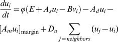
without space leads to the equation  . Three terms
of the right hand side of Equation (1a) or (1b) represent the synthesis,
degradation, and diffusion of the activator or inhibitor, respectively. That
is, the activator is induced by itself in the strength
. Three terms
of the right hand side of Equation (1a) or (1b) represent the synthesis,
degradation, and diffusion of the activator or inhibitor, respectively. That
is, the activator is induced by itself in the strength
 , is repressed by the inhibitor in the intensity of
 , decays at the rate
  , and diffuses
between adjacent cells with the diffusion coefficient
, and diffuses
between adjacent cells with the diffusion coefficient
 . On the other hand, the inhibitor is induced by the
activator in the strength
. On the other hand, the inhibitor is induced by the
activator in the strength  , decays at the
rate D, and diffuses with the diffusion coefficient
, decays at the
rate D, and diffuses with the diffusion coefficient
 . Therefore, the functional strength of WUS is
represented by
. Therefore, the functional strength of WUS is
represented by  in the model,
because the activator and WUS positively regulate each other, in other
words, the activator is self-induced via WUS (Fig. 1A). On the other hand, mutations in
CLV can result in the change of
in the model,
because the activator and WUS positively regulate each other, in other
words, the activator is self-induced via WUS (Fig. 1A). On the other hand, mutations in
CLV can result in the change of
 or
or  .
.
Figure 1. Model framework.

(A) Schematic representation of the WUS-CLV dynamics with respect to
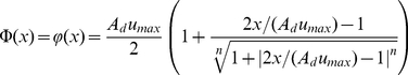
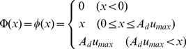
the activator-inhibitor system. (B)  (solid
line, Equation (2a); n = 2.0)
and
(solid
line, Equation (2a); n = 2.0)
and  (dashed line, Equation (2b)) are constraint functions ranged between
0 and
(dashed line, Equation (2b)) are constraint functions ranged between
0 and  . (C)
Schematic representation of a spatially restricted SAM. While
. (C)
Schematic representation of a spatially restricted SAM. While
 is the
threshold of the activator (blue line) for the CZ differentiation,
Zs is the threshold of
diffusible molecule z (red line) for the SAM
differentiation. (D) The SAM is regulated by the interaction between
WUS-CLV dynamics at the molecular level and CZ-PZ relationship at
the tissue level. (E) The procedure of numerical calculations is
divided into four steps (for details, see Materials and Methods).
is the
threshold of the activator (blue line) for the CZ differentiation,
Zs is the threshold of
diffusible molecule z (red line) for the SAM
differentiation. (D) The SAM is regulated by the interaction between
WUS-CLV dynamics at the molecular level and CZ-PZ relationship at
the tissue level. (E) The procedure of numerical calculations is
divided into four steps (for details, see Materials and Methods).
We also examined a simplified version written by
| (3a) |
| (3b) |
with the constraint condition of
 ;
;  if
if
 and
and  if
if
 . Equation (3a) can be obtained from Equation (1a) by
linearizing the activator synthesis and imposing the constraint condition on
the activator concentration instead of its synthesis. A theoretical analysis
indicates that the positive and negative feedback strengths are associated
with
. Equation (3a) can be obtained from Equation (1a) by
linearizing the activator synthesis and imposing the constraint condition on
the activator concentration instead of its synthesis. A theoretical analysis
indicates that the positive and negative feedback strengths are associated
with  and
and  , respectively,
in this simplified dynamics (Fig. 1D, see Methods S1).
, respectively,
in this simplified dynamics (Fig. 1D, see Methods S1).
(II) Spatial restrictions on WUS-CLV dynamics
The SAM in plants is usually limited in its size, indicating that there must
be a mechanism for its spatial restriction. In A. thaliana,
the CZ is known to induce formation of the PZ, but the detailed molecular
mechanism is still unclear [11], [30]. In order to incorporate this feature in our
model, we have assumed that a diffusible factor
( ) is present. The CZ is defined as the cells in which
the activator is expressed at levels greater than the threshold
concentration of
) is present. The CZ is defined as the cells in which
the activator is expressed at levels greater than the threshold
concentration of  (Fig. 1C, blue broken
line). In CZ cells, the diffusible factor z is synthesized
at the rate of
(Fig. 1C, blue broken
line). In CZ cells, the diffusible factor z is synthesized
at the rate of  ; diffusion of
the factor generates a gradient (Fig. 1C, red solid line) and induces
formation of the PZ. The PZ and OZ are differentiated by having a
z concentration higher or lower, respectively, than a
fixed threshold value (
; diffusion of
the factor generates a gradient (Fig. 1C, red solid line) and induces
formation of the PZ. The PZ and OZ are differentiated by having a
z concentration higher or lower, respectively, than a
fixed threshold value ( ) (Fig. 1C, red broken line).
Accordingly, parameter
) (Fig. 1C, red broken line).
Accordingly, parameter  represents the
strength of PZ induction (Fig.
1D). The dynamic interaction of WUS and CLV is spatially
restricted to the CZ and PZ and does not occur in the OZ, by limiting the
activator synthesis to the CZ and PZ. Thus, in PZ cells, the activator is
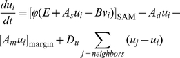
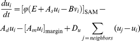
synthesized but remains at very low levels (Fig. 1C). The basic dynamics including
the spatial restriction is described by the following
equations:
represents the
strength of PZ induction (Fig.
1D). The dynamic interaction of WUS and CLV is spatially
restricted to the CZ and PZ and does not occur in the OZ, by limiting the
activator synthesis to the CZ and PZ. Thus, in PZ cells, the activator is
synthesized but remains at very low levels (Fig. 1C). The basic dynamics including
the spatial restriction is described by the following
equations:
| (4a) |
| (4b) |
| (4c) |
with
| (5a) |
| (5b) |
where
 ,
,  ,
,
 ,
,  , and
, and
 are positive constants. Note that, in this model,
the SAM is controlled by the interaction between two regulations: WUS-CLV
dynamics at the molecular level and CZ-PZ relationship at the tissue level
(Fig. 1D). That is,
WUS-CLV dynamics induces the CZ and subsequent PZ, and in turn the SAM
spatially defines WUS-CLV activity.
are positive constants. Note that, in this model,
the SAM is controlled by the interaction between two regulations: WUS-CLV
dynamics at the molecular level and CZ-PZ relationship at the tissue level
(Fig. 1D). That is,
WUS-CLV dynamics induces the CZ and subsequent PZ, and in turn the SAM
spatially defines WUS-CLV activity.
The numerical simulations were performed by a repeated sequence of all or subsets of the four steps: cell network dynamics, reaction-diffusion dynamics, cell removal, and cell division (Fig. 1E). In the steps of the cell network dynamics and reaction-diffusion dynamics, numerical calculations were carried out until an almost steady state. Detailed conditions and parameter values of each numerical analysis are described in Material and Methods, Methods S1, and Table S1.
Effect of Expressional Separation Between WUS and CLV3
The expression pattern of WUS-CLV dynamics is spatially regulated in a
two-dimensional manner, because its expression domain changes drastically in the
lateral direction by defects in the dynamics but does not longitudinally across
cell layers [18]–[20], [23], [30]. We therefore modeled SAM pattern formation in
two-dimensional space. CLV3 is, however, exclusively expressed
in the outermost cell layers, while WUS is expressed in the
underlying layers [10]–[13], [18], [24]. We examined the effect of this expressional
separation using a simplified two-layered cell network. This analysis indicated
that while stable patterns develop in the absence of any expressional
restrictions (Fig. S1A), they are completely disrupted by introducing expressional
separation in which the activator and inhibitor are synthesized only in the
lower or upper layers, respectively (Fig. S1B). We presume that this disappearance
of patterning results from the retardation of signal transition from the
activator to the inhibitor, because activator synthesized in the lower layer
cannot induce the inhibitor until after reaching the upper layer. In fact,
stable patterns are restored by adding another diffusible factor
( ) into the signaling pathway from the activator to
inhibitor (Fig.
S1C). Furthermore, the patterns depended on the diffusion coefficient
of this factor (Fig. S1D). That is, pattern restoration requires that the diffusion
coefficient of
) into the signaling pathway from the activator to
inhibitor (Fig.
S1C). Furthermore, the patterns depended on the diffusion coefficient
of this factor (Fig. S1D). That is, pattern restoration requires that the diffusion
coefficient of  (
( ) is sufficiently larger than that of the activator
(
) is sufficiently larger than that of the activator
( ) (Fig. S1D). This evidence suggests that the
CLV3 induction pathway involves an unknown diffusible
signal molecule other than the activator. These results indicate that pattern
formation caused by WUS-CLV dynamics in the SAM is essentially governed by the
activator-inhibitor mechanism. Therefore, for simplification, we performed the
numerical analyses described below using a conventional activator-inhibitor
system in Fig. 1A, with
single-layered cell networks.
) (Fig. S1D). This evidence suggests that the
CLV3 induction pathway involves an unknown diffusible
signal molecule other than the activator. These results indicate that pattern
formation caused by WUS-CLV dynamics in the SAM is essentially governed by the
activator-inhibitor mechanism. Therefore, for simplification, we performed the
numerical analyses described below using a conventional activator-inhibitor
system in Fig. 1A, with
single-layered cell networks.
Stem Cell Proliferation Mode
(I) Pattern evolution caused by area expansion
Since the SAM has the potential for continuous growth due to active cell division, we first investigated the effect of cell division in the absence of any spatial restrictions. This analysis showed that pattern evolution could be classified into four modes:
Elongation mode: an initial spot with high activator concentrations continues to elongate to form stripes as the meristem grows (Fig. 2E and Movie S4).
Division mode: spots continue to multiply by binary fission after their elongation (Fig. 2D and Movie S3).
Emergence mode: spots multiply by the appearance of new spots from areas free of these (Fig. 2C and Movie S2). These three modes generate stable patterns with strong expression of the activator.
Fluctuation mode: spots with weak activator levels continuously move and also elongate, increase by division, and merge with neighboring spots (Fig. 2B and Movie S1).
Figure 2. Stem cell proliferation modes.

(A) The proliferation mode clearly depends on parameters
 and
and
 .
(B–E) Pattern evolution of the reaction-diffusion system in
relation to cell division is classified into four proliferation
groups: the fluctuation mode (B), emergence mode (C), division mode
(D), and elongation mode (E). See also Movies
S1, S2, S3, S4 (B–E, respectively). The
intensity of the blue indicates the activator concentration
(B–E).
.
(B–E) Pattern evolution of the reaction-diffusion system in
relation to cell division is classified into four proliferation
groups: the fluctuation mode (B), emergence mode (C), division mode
(D), and elongation mode (E). See also Movies
S1, S2, S3, S4 (B–E, respectively). The
intensity of the blue indicates the activator concentration
(B–E).
These proliferation patterns during area expansion are similar to those
identified in previous numerical studies [4], [31], [32].
Since the region with high activator concentrations corresponds to the CZ or
the stem cells, the proliferation mode represents the growth pattern of stem
cells in the absence of spatial restrictions. The proliferation mode is
affected by the dynamic balance between the positive and negative feedback
loops. Thus, the mode shifts sequentially from elongation, to division, then
to emergence, and finally to the fluctuation mode as the negative feedback
increases in strength compared with the positive feedback by decreasing
 or increasing
  (Fig. 2A). The effect of
 on the proliferation mode is the same as that of
 (compare with Fig.
S2). This fact is consistent with a theoretical analysis (see Methods
S1). In addition, a similar effect on the proliferation mode is
obtained in the simplified dynamics expressed by Equations (3) (Fig.
S3). This result indicates that the proliferation mode is not
qualitatively affected by the nonlinearity of the dynamics.
(compare with Fig.
S2). This fact is consistent with a theoretical analysis (see Methods
S1). In addition, a similar effect on the proliferation mode is
obtained in the simplified dynamics expressed by Equations (3) (Fig.
S3). This result indicates that the proliferation mode is not
qualitatively affected by the nonlinearity of the dynamics.
(II) Effect of constraint condition of the dynamics
It is known that the constraint condition has a crucial effect on pattern formation in reaction-diffusion systems. For example, while the activator-inhibitor system can generate spotted, striped, or reverse spotted patterns on a fixed two-dimensional plane [2]–[4], [33], these patterns are responsive to the ratio of distances from the equilibrium to the upper and lower limitations of the activator [33]. That is, the spotted pattern, the reverse spotted pattern, and the striped pattern are generated when the equilibrium is closer to the lower limitation, or closer to the upper limitation, or equally distant from the both limitations, respectively.
Our model dynamics explicitly includes the constraint condition of the
activator, and it is shown that this constraint has crucial effects on the
proliferation mode during cell division (Fig.
S4A). When the equilibrium of the activator is situated at the
exact middle between the upper and lower limitations (Fig.
S4A,  ), regions with
high and low activator concentrations cover almost equivalent areas,
resulting in the stripe mode (Fig. S4B). As the upper limitation
becomes high by increasing
), regions with
high and low activator concentrations cover almost equivalent areas,
resulting in the stripe mode (Fig. S4B). As the upper limitation
becomes high by increasing  , the region
with high concentrations becomes small compared to that with low
concentrations, and accordingly becomes to generate spots rather than
stripes. Resultantly the pattern shifts to the elongation mode, division
mode, fluctuation mode, and emergence mode (Fig.
S4A,
, the region
with high concentrations becomes small compared to that with low
concentrations, and accordingly becomes to generate spots rather than
stripes. Resultantly the pattern shifts to the elongation mode, division
mode, fluctuation mode, and emergence mode (Fig.
S4A,  ). In contrast,
as the upper limitation becomes low by decreasing
). In contrast,
as the upper limitation becomes low by decreasing
 , the pattern shifts to the reverse elongation mode
(Fig.
S4C), reverse division mode (Fig.
S4D), reverse fluctuation mode (Fig.
S4E), and reverse emergence mode (Fig.
S4F). In these cases, spots with low concentrations grow
according to each proliferation mode. The SAM of plants probably has the
condition that can generate the spotted pattern, because the expression of
WUS-CLV system usually results in a spot-like appearance. Therefore, we used
a large value of
, the pattern shifts to the reverse elongation mode
(Fig.
S4C), reverse division mode (Fig.
S4D), reverse fluctuation mode (Fig.
S4E), and reverse emergence mode (Fig.
S4F). In these cases, spots with low concentrations grow
according to each proliferation mode. The SAM of plants probably has the
condition that can generate the spotted pattern, because the expression of
WUS-CLV system usually results in a spot-like appearance. Therefore, we used
a large value of  in the
numerical simulations in this article.
in the
numerical simulations in this article.
SAM Patterns Generated by the Model
The SAM in plants usually does not proliferate indefinitely but is strongly limited to a small area. Accordingly, we investigated the effect of spatial restriction. In this analysis, the SAM patterns that developed from an initial CZ spot are divided into six groups according to their structure and proliferation (Fig. 3).
Figure 3. SAM patterns generated by the model.

(A) The model generates different SAM patterns by varying
 (WUS-CLV
dynamics) and
(WUS-CLV
dynamics) and  (the
spatial restriction). Crosses indicate situations where no patterns are
generated. (B–H) SAM patterns can be divided into six groups
according to their structure and proliferation mode. See also Movies
S5, S6, S7,
S8, S9, S10, S11 (B–H, respectively). Blue
and red indicate the activator concentration in the CZ and PZ,
respectively. The green area indicates the OZ.
(the
spatial restriction). Crosses indicate situations where no patterns are
generated. (B–H) SAM patterns can be divided into six groups
according to their structure and proliferation mode. See also Movies
S5, S6, S7,
S8, S9, S10, S11 (B–H, respectively). Blue
and red indicate the activator concentration in the CZ and PZ,
respectively. The green area indicates the OZ.
(I) Runaway proliferation
When there is strong induction of the PZ due to a large Z component, the resulting patterns of proliferation produce an enlarged SAM with spots or stripes of the CZ. (i) The fasciation pattern produces an enlarged SAM with a strikingly elongated CZ by the elongation mode (Fig. 3B and Movies S5). (ii) The multiplication pattern generates multiple CZ spots by the division mode (Fig. 3C and Movie S6) or by the emergence mode (Fig. 3D and Movie S7). (iii) The fluctuation pattern forms multiple weak CZ spots that proliferate by the fluctuation mode (Fig. 3E and Movie S8). In these patterns, runaway proliferation of stem cells is caused by a chain reaction between PZ expansion and CZ growth.
(II) SAM breakdown
In contrast to runaway proliferation, when there is weak PZ induction due to
a small Z, the PZ area induced by the CZ is too small to
maintain the CZ cells, leading to the disappearance of the CZ and subsequent
breakdown of the SAM (Fig.
3A,  ).
).
(III) Homeostasis pattern
Under the intermediate condition between runaway proliferation and SAM breakdown, (iv) a homeostasis pattern appears in which the SAM keeps an almost constant cell population with a single CZ spot at its center (Fig. 3F and Movie S9). This results from a balance between cell multiplication by division and cell loss from the SAM. In other words, through the homeostasis pattern, the plant prevents runaway proliferation of the stem cells by constricting the size of the meristem. We named this effect “stem cell containment”. Whether or not containment occurs will depend on the proliferation mode: containment readily occurs in the division and emergence modes, but is difficult in the elongation and fluctuation modes (Fig. 3A).
(IV) Branching-related patterns
The intermediate condition between the homeostasis pattern and runaway proliferation produces patterns related to shoot branching, in which each CZ spot develops into a separate independent SAM (Fig. 3A). These patterns fall into two classes according to their proliferation mode: (v) dichotomous pattern by the division mode (Fig. 3G and Movie S10) and (vi) monopodial pattern by the emergence mode (Fig. 3H and Movie S11). The two patterns respectively resemble dichotomous branching and monopodial branching in plant shoots.
(V) Effect of relative frequency of cell division between CZ, PZ, and OZ
It is known that cell division rate in the SAM is distinct between the CZ and PZ, that is, the PZ shows a more rapid rate of cell division than the CZ [34], [35]. Thus we investigated the effect of relative frequency of cell division on the SAM pattern formation. A variety of relative frequencies does not affect the homeostasis pattern formation, with the exception that extremely high division rates in the PZ compared to the CZ generate the dichotomous pattern (Fig. S5). This result suggests that spatial heterogeneity of cell division activity does not have a large effect on the SAM patterning.
Regulation of SAM Patterns in Plants
SAM patterning with regard to the WUS and CLV
genes (which are associated with  and
and
 , respectively, in our model) has been intensively
studied in A. thaliana
[10]–[13]. Thus, the effect of
, respectively, in our model) has been intensively
studied in A. thaliana
[10]–[13]. Thus, the effect of  ,
,
 and
and  was investigated
in detail under an intermediate containment condition that induces the
homeostasis pattern. As
was investigated
in detail under an intermediate containment condition that induces the
homeostasis pattern. As  increases or
 is reduced, the SAM pattern shifts from SAM breakdown,
to the fluctuation pattern, then to the homeostasis pattern, then to the
dichotomous pattern and finally to the fasciation pattern (Fig. 4A and Fig. S6).
That is,
is reduced, the SAM pattern shifts from SAM breakdown,
to the fluctuation pattern, then to the homeostasis pattern, then to the
dichotomous pattern and finally to the fasciation pattern (Fig. 4A and Fig. S6).
That is,  and
and  parameters have
opposite effects (Fig.
4C).
parameters have
opposite effects (Fig.
4C).
Figure 4. Effect of WUS and CLV on SAM patterning.

(A) As  increases or
  decreases,
the SAM pattern shifts sequentially from the fluctuation pattern (filled
diamonds), to the homeostasis pattern (open circles), then to the
dichotomous pattern (open squares), and finally to the fasciation
pattern (filled circles). Crosses indicate situations where no patterns
are generated, and filled square indicates the multiplication pattern by
the division mode. (B) The SAM area in the homeostasis pattern expands
as
decreases,
the SAM pattern shifts sequentially from the fluctuation pattern (filled
diamonds), to the homeostasis pattern (open circles), then to the
dichotomous pattern (open squares), and finally to the fasciation
pattern (filled circles). Crosses indicate situations where no patterns
are generated, and filled square indicates the multiplication pattern by
the division mode. (B) The SAM area in the homeostasis pattern expands
as  increases or
  decreases.
The blue and red areas indicate the relative sizes of the CZ and PZ,
respectively. (C) The effect of
decreases.
The blue and red areas indicate the relative sizes of the CZ and PZ,
respectively. (C) The effect of  and
and
 on the SAM
patterning is summarized schematically. The predictions of our model
agree with many experimental results (for details, see text). The blue,
red, and green areas indicate the CZ, PZ, and OZ, respectively.
on the SAM
patterning is summarized schematically. The predictions of our model
agree with many experimental results (for details, see text). The blue,
red, and green areas indicate the CZ, PZ, and OZ, respectively.
(I) Wild type
It is evident that development of the wild type is morphologically related to the homeostasis pattern because the both keep a constant SAM size despite active cell division. In order to prove this relationship, we examined the expression pattern of a pWUS::GUS reporter that reflected the activity of the activator. As has been reported in many studies [19]–[26], strong expression of the reporter is detected as a single spot at the center of the SAM (Fig. 5A). This finding confirms that the wild-type SAM of A. thaliana corresponds to the homeostasis pattern of our model (Fig. 4C).
Figure 5. Expression patterns of the pWUS::GUS reporter construct.

Top view of the SAM in wild type Ler (A) and wus-1 (B) plants. Wild-type plants show strong β-glucuronidase (GUS) activity as a single spot at the center of the SAM (A, arrowhead). In contrast, wus-1 plants have an enlarged SAM with multiple foci of expression at very weak levels (B, arrowheads). Ten-day-old seedlings were stained with GUS overnight. The broken lines indicate the extent of the SAM. Scale bars, 10 µm.
(II) SAM size
SAM size in the homeostasis pattern can be expanded by increasing
 or decreasing
  (Fig. 4B). It is generally
believed that the SAM size in plants is controlled by two separate effects:
first, the CZ restricts its own domain by preventing transition of PZ cells
into the CZ; in addition, the CZ restricts overall SAM size by preventing
differentiation of PZ cells into OZ [11], [30]. The former effect is
obviously derived from the property that Turing pattern has its intrinsic
spatial scale (Methods S1) [4]. On the other hand, the
latter is rather related to stem cell containment, namely, PZ induction. The
cooperation of the two effects determines overall SAM size.
(Fig. 4B). It is generally
believed that the SAM size in plants is controlled by two separate effects:
first, the CZ restricts its own domain by preventing transition of PZ cells
into the CZ; in addition, the CZ restricts overall SAM size by preventing
differentiation of PZ cells into OZ [11], [30]. The former effect is
obviously derived from the property that Turing pattern has its intrinsic
spatial scale (Methods S1) [4]. On the other hand, the
latter is rather related to stem cell containment, namely, PZ induction. The
cooperation of the two effects determines overall SAM size.
(III) wus mutant
The model predicts that a decrease in parameter
 will change the wild-type homeostasis pattern to the
fluctuation pattern or SAM breakdown (Fig. 4C). This prediction is supported by
the similar morphological features of the wus mutant and
the fluctuation pattern, namely, an enlarged SAM and secondary meristems
initiated ectopically across the SAM (Fig. 3E) [17]. Furthermore, because
expression pattern of WUS in wus mutant
has not been investigated in detail, we examined in a null allele
wus-1. We found that the expression pattern of a
pWUS::GUS reporter in the wus-1 mutant
showed a patchy pattern at very weak levels compared to the wild type (Fig. 5B). These
morphological and expressional similarities confirm the relationship between
the wus mutant and the fluctuation pattern.
will change the wild-type homeostasis pattern to the
fluctuation pattern or SAM breakdown (Fig. 4C). This prediction is supported by
the similar morphological features of the wus mutant and
the fluctuation pattern, namely, an enlarged SAM and secondary meristems
initiated ectopically across the SAM (Fig. 3E) [17]. Furthermore, because
expression pattern of WUS in wus mutant
has not been investigated in detail, we examined in a null allele
wus-1. We found that the expression pattern of a
pWUS::GUS reporter in the wus-1 mutant
showed a patchy pattern at very weak levels compared to the wild type (Fig. 5B). These
morphological and expressional similarities confirm the relationship between
the wus mutant and the fluctuation pattern.
(IV) stip mutant
Mutation of STIP (also known as WOX9), which encodes a WUS homolog, produces a phenotype that is similar to but more severe than strong wus mutants [36]. That is, secondary shoots are never formed due to failure of growth of the vegetative SAM in the stip mutant. In addition, the SAM of stip lacks WUS expression. This indicates that a drastic reduction in the positive feedback causes the elimination of WUS expression and subsequent SAM breakdown in stip.
(V) WUS overexpression
Our model predicts that an intensified positive feedback will lead to the dichotomous or fasciation pattern (Fig. 4C). An enlarged fasciated SAM, similar to that of the clv mutant, is caused by strong ectopic expression of WUS under the CLV1 promoter in the OC and the surrounding region [19], [23]. This morphological defect can be generated by numerical simulations using similar conditions (Figs. 6B and Fig. S7A).
Figure 6. Numerical simulations for experiments affecting SAM patterning.

(A) Conditional knockdown of CLV3 causes a gradual expansion of the CZ area. (B–C) Ectopic expression of pCLV1::WUS (B) or pCLV1::CLV3 (C) causes clv-like and wus-like SAM morphologies, respectively. (D–E) CZ spots reform after ablation of the CZ cells. CZ foci reform as either a single (D) or two spots (E). (F) As a result of the incision through the meristem center, the two halves reorganize into two new meristems. See also Fig. S2A (B), S2B (C), and Movies S12, S13, S14, S15 (A, D, E and F, respectively). Blue and red indicate the activator concentration in the CZ and PZ, respectively. The green area indicates the OZ.
(VI) Cytokinin effect
The plant hormone cytokinin stimulates the positive feedback pathway
involving WUS, and thereby causes expansion of the
WUS expression domain [26]. Knockdown of the
ARR7 and ARR15 genes, negative
regulators of cytokinin signaling, causes both increase of
WUS expression and enlarged meristems [37]. On the
other hand, SAM size is diminished by decreasing cytokinin levels [38], [39] and
by defects in its signal transduction [40], [41]. In addition,
WUS expression is also reduced by the defect of AHK2, a
cytokinin receptor [26]. These experimental results are consistent with
the outcome of changing parameter  in the model
(Fig. 4C). The
relatively weak effects of cytokinin compared to those of
wus mutation suggest that cytokinin has a limited
involvement in the feedback regulation.
in the model
(Fig. 4C). The
relatively weak effects of cytokinin compared to those of
wus mutation suggest that cytokinin has a limited
involvement in the feedback regulation.
(VII) clv mutants
Defects in clv cause morphological abnormalities such as
enlarged, fasciated, or bifurcated SAMs [14]–[16]. In
addition, these structural changes are correlated strongly with the
expression pattern of WUS. That is, WUS
expression is expanded in enlarged SAMs and is elongated in fasciated SAMs
[19],
[20],
[26].
These results also agree with the predictions of the model as
CLV defects cause a reduction in parameter
 (Fig.
4C).
(Fig.
4C).
(VIII) CLV3 knockdown
The conditional knockdown of CLV3 results in a gradual expansion of the pCLV3::GFP expression area [30]. This observation is consistent with the expectations of our model (Fig. 6A and Movie S12).
(IX) CLV3 overexpression
Reinforcement of the negative feedback is expected to produce a diminished homeostatic SAM, or the fluctuation pattern, or SAM breakdown (Fig. 4C). The introduction of multiple copies of CLV3, under its own promoter, reduces both the WUS-expressing domain and SAM size [23]. The relatively weak effect in this case may be due to buffering by the WUS-CLV system [23]. In addition, ectopic expression of CLV3 under the CLV1 promoter resulted in a wus-like SAM, which is closely associated with the fluctuation pattern [23]. This change in the SAM can also be produced by numerical simulations under similar conditions (Figs. 6C and Fig. S7B). Moreover, the SAM of many p35S::CLV3 transgenic plants ceases to initiate organs after the emergence of the first leaves [20]. This is due to strong inhibition against the activator that precludes pattern formation, resulting in SAM breakdown.
(X) pt mutant
The mutant defective in PT (also known as AMP1, COP2, and HPT) forms an enlarged SAM with discrete spots of CLV3 expression and a subsequent excess of shoots [42], [43]. These results strongly indicate that pt is related to the multiplication pattern in the model.
(XI) Meristem reorganization
In tomato, the CZ can be regenerated following laser ablation of CZ cells [44]. Our model can also produce this regeneration process (Fig. 6DE and Movies S13, S14). After CZ ablation, the activator is transiently induced in a ring-shaped region of the PZ (Fig. 6D, t = 10). Then, the high activator region is gradually restricted to a few spots (Fig. 6D, t = 40), each of which develops a stable CZ spot if the activator level exceeds the threshold for CZ (Fig. 6D, t = 100). This modeled regeneration process is similar to that observed in the ablation experiments [44].
In addition, the incision through the meristem center by laser ablation causes reorganization into two new meristems in tomato [45]. This experimental observation is also consistent with a model prediction (Fig. 6F and Movie S15). That is, after the incision, the activator expression is transiently reduced and dispersed (Fig. 6F, t = 10), but is then gradually reorganized at the center of each meristem half (Fig. 6F, t = 40). Finally, stable CZ spots are regenerated (Fig. 6F, t = 200).
Discussion
We show here that SAM patterning is essentially governed by only two parameters: the proliferation mode and stem cell containment (Fig. 7). The proliferation mode is defined by the dynamics of a molecular network, such as WUS-CLV interaction in A. thaliana. We also show that the proliferation mode has only four groups, and this is a common property of Turing systems [4], [31], [32]. Accordingly, the summary of our results in Fig. 7 is applicable not only to A. thaliana but also to all other plant species. However, since the dynamics of each regulatory network may favor particular proliferation modes, it is likely that each plant species also show preferred patterns. On the other hand, stem cell containment is achieved through a spatial restriction mechanism. Under conditions of overly strong containment, a plant will die because of SAM breakdown; however, with weak containment, the plant loses control over the SAM resulting in excessive shoots. By contrast, under intermediate containment conditions, a plant can control the cell populations in the SAM. It is likely that this homeostasis pattern is present in most plant species including A. thaliana. This result also provides an insight into why and how most plant species have a main shoot axis with a constant diameter.
Figure 7. Model for SAM patterning.

SAM pattern essentially depends on the proliferation mode and stem cell containment strength. The proliferation mode can be sub-divided into four groups, depending on the molecular dynamics regulating the SAM, such as WUS-CLV dynamics of A. thaliana. On the other hand, stem cell containment is associated with the spatial restriction of the dynamics. The blue, red and green areas indicate the CZ, PZ and OZ, respectively.
The branching of plant shoots is classified into two types: dichotomous or monopodial. Dichotomous branching, as is observed in Psilotum, appears to be the equivalent of the dichotomous pattern in our model. In contrast, it is likely that the lateral branches observed in many plant species are not associated with the monopodial pattern but rather are controlled by the distinct dynamics of auxin and its carrier, PIN1, because shoots in the pin1 mutant of A. thaliana elongate normally but fail to generate lateral branches [46]. Our model also provides an insight into how shoot structures of plants has evolved between monopodial shoot axis and dichotomous shoot branching.
For extending the model of this article to explain the pattern of a three-dimensional shoot, it is first required to introduce a three-dimensional cell network system that is capable of cell division. Furthermore, in order to generate the correct three-dimensional pattern of WUS-CLV expression, it seems to need spatial restrictions according to cell layer. As described in the above, spatial expressions of WUS and CLV3 are strongly limited to the outermost cell layers and the underlying layers, respectively. It is likely that these spatial restrictions are not regulated by WUS-CLV dynamics itself but rather depend on an unknown upstream signaling pathway associated with cell layer differentiation. Therefore, these expressional limitations according to cell layer are required for simulating a three-dimensional meristem.
Over half a century ago, Turing first proposed the reaction-diffusion mechanism as the basis for self-organization and pattern formation in biological systems [1]. In several developmental events of animals, candidate molecules that play a central role in pattern formation by the reaction-diffusion mechanism have been proposed [6], [7]. However, it would be difficult to demonstrate reaction-diffusion activity in these cases, because morphogenetic processes in most of them are irreversible and experimental perturbations may be lethal. By contrast, the SAM of plants repetitively produces new organs throughout the lifespan. In order to demonstrate the reaction-diffusion pattern in living systems, it is thought that two lines of evidence are required [6], [7]. One is the identification of elements of interactive networks that fulfill the criteria of short-range positive feedback and long-range negative feedback. By a number of experimental studies, WUS-CLV dynamics clearly satisfies the criteria in the SAM pattern formation [10]–[13]. The other requirement is to show that a reaction-diffusion wave exists, that is, we need to identify dynamic properties of the reaction-diffusion pattern that is predicted by the computer simulation. In the case of the SAM, results of earlier studies suggest that WUS-CLV dynamics satisfies this requirement [27]–[29]. Furthermore, the findings of this article strongly reinforce this argument. Accordingly, it appears that WUS-CLV dynamics fulfills the requirement for demonstrating the reaction-diffusion pattern in the SAM. We thus conclude that the reaction-diffusion mechanism is probably indispensable for the SAM development of plants.
Materials and Methods
GUS Staining Analysis
The pWUS::GUS reporter line [47] was crossed with wus-1/+ heterozygous plants to produce pWUS::GUS+ wus-1/+ F1 plants. pWUS::GUS expression was analyzed in wus-1 homozygotes in the F2 generation. β-glucuronidase (GUS) staining of whole mount SAMs was performed largely as previously described [19], except for use of 10 mM potassium-ferricyanide as the staining buffer. Samples were cleared in 70% ethanol and mounted in chloral hydrate. The expression pattern of pWUS::GUS was analyzed using a Zeiss AxioPlan2 microscope.
Numerical Calculations
The numerical calculations were implemented in C, and the cell network dynamics and reaction-diffusion dynamics were integrated using the Euler method. The graphics of cell networks was made in Mathematica ver.4.2 (Wolfram Research Inc.).
The numerical simulations were performed by a repeated sequence of all or subsets
of the four steps: cell network dynamics, reaction-diffusion dynamics, cell
removal, and cell division (Fig.
1F). In the steps of the cell network dynamics and reaction-diffusion
dynamics, numerical calculations were carried out until an almost steady state.
That is, the step of the cell network dynamics was carried out with the total
time 10.0 and the time step  , while the step of
the reaction-diffusion dynamics was done with the total time
, while the step of
the reaction-diffusion dynamics was done with the total time
 and the time step
  .
.
As the shoot lengthens, cells become increasingly distant to the SAM with
downward move. To accommodate this fact, cells leave the cell networks after
becoming sufficiently distant from the SAM. That is, in the cell removal step,
we remove cells from the cell network if  is lower than a
threshold level,
is lower than a
threshold level,  , that is smaller
than
, that is smaller
than  . In the cell division step, the largest cell divides in
a random direction with the exception of Fig S5.
. In the cell division step, the largest cell divides in
a random direction with the exception of Fig S5.
The initial value of variables was given as their equilibrium with a random fluctuation of 1.0%, and numerical simulations of the reaction-diffusion dynamics were imposed on the boundary condition of zero flux. Steps and parameter values used in each numerical simulation are summarized in Table S1.
Numerical Condition in Figure S1
A two-layered lattice was obtained by the periclinal division of a single-layered lattice with 1,000 cells generated by cell division from an initial lattice with four cells. We examined three spatial restriction conditions by varying activator and inhibitor syntheses. In Fig. S1A, the activator and inhibitor are synthesized in all the cells using Equations (1) and (2a). By contrast, in Fig. S1B, they are synthesized separately in the upper and lower layers with the equations of
| (6a) |
| (6b) |
with
| (7a) |
| (7b) |
In
Fig. S1C and
D, a diffusible molecule  was introduced
into the dynamics of Equations (6); this molecule is active in the signal
transduction pathway from the activator to the inhibitor. Then the set of
differential equations used is given by
was introduced
into the dynamics of Equations (6); this molecule is active in the signal
transduction pathway from the activator to the inhibitor. Then the set of
differential equations used is given by
| (8a) |
| (8b) |
| (8c) |
where  is a constant.
Thus
is a constant.
Thus  is induced by the activator, diffuses with the diffusion
coefficient
is induced by the activator, diffuses with the diffusion
coefficient  , and stimulates the inhibitor.
Numerical condition in Figures 2 and S2, S3, S4
Cell number increased from 10 to 1,000 cells without cell removal. We used Equations (1) and (2a) in Fig. 2A and S2, Equations (3) in Fig. S3, and Equations (1) and (2b) in Fig. S4. In Fig. 2B–E, we used the following modified version from Equations (1);
 |
(9a) |
| (9b) |
with
| (10) |
where  is a positive
constant. Thus the activator has a higher rate of degradation in marginal cells
than in non-marginal cells, and this condition prevents CZ spots from migrateing
to the edge of the cell network.
is a positive
constant. Thus the activator has a higher rate of degradation in marginal cells
than in non-marginal cells, and this condition prevents CZ spots from migrateing
to the edge of the cell network.
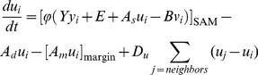
Numerical Condition in Figures 3, 4, and S6
We used the following form modified from Equations (4);
 |
(11a) |
| (11b) |
| (11c) |
where positive constant
 is introduced in order to prevent CZ spots from
migrating to the edge of the cell network as in the case of Equations (9).
Pattern development by a Turing system requires a minimal area size that depends
on dynamics parameters [4]. Accordingly, in the previous step, the activator is
synthesized in all cells and cell number is increased without cell removal,
until a CZ spot emerges and is maintained stably in the center of the SAM. Then,
the dynamics expressed by Equations (11) was applied until the cell population
reach 1000 cells together with removal cells. The resultant SAM patterns were
subjected to pattern classification. The dominant pattern for each set of
parameter conditions was determined after at least ten independent numerical
simulations.
is introduced in order to prevent CZ spots from
migrating to the edge of the cell network as in the case of Equations (9).
Pattern development by a Turing system requires a minimal area size that depends
on dynamics parameters [4]. Accordingly, in the previous step, the activator is
synthesized in all cells and cell number is increased without cell removal,
until a CZ spot emerges and is maintained stably in the center of the SAM. Then,
the dynamics expressed by Equations (11) was applied until the cell population
reach 1000 cells together with removal cells. The resultant SAM patterns were
subjected to pattern classification. The dominant pattern for each set of
parameter conditions was determined after at least ten independent numerical
simulations.
Numerical Condition in Figure S5
Numerical simulations were carried out as in Fig. 3F except for the cell division step.
Cell division occurs in the cell with the largest value of multiplying its cell
volume by a constant factor;  in CZ,
 in PZ, or
  in OZ. Therefore,
the activity of cell division becomes high according to the increase in this
factor. The dominant pattern for each set of parameter conditions was determined
after at least ten independent numerical simulations.
in OZ. Therefore,
the activity of cell division becomes high according to the increase in this
factor. The dominant pattern for each set of parameter conditions was determined
after at least ten independent numerical simulations.
Numerical condition in Figure 6A
The homeostasis pattern was initially generated as in Fig. 3F, and then the synthesis of the inhibitor was interrupted by reducing parameter C to zero.
Numerical Condition in Figures 6BC and S7
CLV1 is strongly expressed in the OC and its surrounding region;
however, the regulatory mechanism of this expression pattern has not yet been
clarified. We, therefore, assumed a diffusible signal molecule
( ) that is induced by the activator, and diffuses at the
rate
) that is induced by the activator, and diffuses at the
rate  to stimulate the CLV1 promoter with an
intensity of
to stimulate the CLV1 promoter with an
intensity of  (see Fig. S7). Consequently, sets of equations
under the condition overexpressed by the CLV1 promoter are
described by
(see Fig. S7). Consequently, sets of equations
under the condition overexpressed by the CLV1 promoter are
described by
 |
(12a) |
| (12b) |
| (12c) |
| (12d) |
for pCLV1::WUS (Figs. 6B and S7A) and
 |
(13a) |
| (13b) |
| (13c) |
| (13d) |
for pCLV1::CLV3 (Figs. 6C and S7B). The dominant pattern for each set of parameter conditions was determined after at least ten independent numerical simulations.
Numerical Condition in Figure 6D–F
After SAM in the homeostasis state was initially generated as in Fig. 2F, the CZ cells (Fig. 6DE) or a line of cells through the meristem center (Fig 6F) was removed from the cell network. Then the calculations were carried out in the same way as before the cell ablation.
Supporting Information
Effect of expressional separation between the activator and inhibitor in a two-layered cell network. (A) Stable patterns are developed without any spatial restrictions under the Turing condition (inside the dashed lines, see Methods S1). (B) However, stable patterns are completely eliminated by introducing expressional separation in which the activator and inhibitor are synthesized only in the lower and upper cell layers, respectively. (C) In contrast, stable patterns are restored by introducing another diffusible signal molecule (x) into the signaling pathway from the activator to the inhibitor. (D) Pattern restoration requires that the diffusion coefficient of x (Dx) is sufficiently larger than that of the activator (Du = 0.25). Filled circles and crosses indicate stable patterns and no stable patterns, respectively. In A–C, the area enclosed by the dashed lines indicates the Turing condition of Equations (3) (see Methods S1).
(EPS)
Effect of
C
on the
proliferation mode. Parameter  has the same
effect as
has the same
effect as  on the proliferation mode (compare with Fig. 2A).
(EPS)
Effect of a simplified dynamics on the proliferation mode. The simplified activator-inhibitor dynamics described by Equations (3) shows a similar result to that by Equations (1) (compare with Fig. 2A).
(EPS)
Effect of the upper limitation of the activator on the proliferation
mode. (A) Patterns are responsive to the ratio of distances from
the equilibrium of the activator ( ) to the upper
limitation (
) to the upper
limitation ( ) and lower
limitation (
) and lower
limitation ( ). (B–F)
Pattern evolutions of the stripe mode (B, double circles), reverse
fluctuation mode (C, open diamonds), reverse emergence mode (D, open
triangles), reverse division mode (E, open squares), and reverse elongation
mode (F, open circles). Filled diamonds, filled triangles, filled squares,
and filled circles indicate the fluctuation mode, emergence mode, division
mode, and elongation mode, respectively.
). (B–F)
Pattern evolutions of the stripe mode (B, double circles), reverse
fluctuation mode (C, open diamonds), reverse emergence mode (D, open
triangles), reverse division mode (E, open squares), and reverse elongation
mode (F, open circles). Filled diamonds, filled triangles, filled squares,
and filled circles indicate the fluctuation mode, emergence mode, division
mode, and elongation mode, respectively.
(EPS)
Effect of relative frequency of cell division between CZ, PZ, and OZ on
the homeostasis pattern formation. Cell division frequency is
varied by changing parameters  and
and
 (for detail see Materials and Methods). Blue, magenta, and green in bar graphs
indicate relative frequency of cell division in CZ, PZ, and OZ,
respectively. Open circles and open squares indicate the homeostasis pattern
and dichotomous pattern, respectively.
(for detail see Materials and Methods). Blue, magenta, and green in bar graphs
indicate relative frequency of cell division in CZ, PZ, and OZ,
respectively. Open circles and open squares indicate the homeostasis pattern
and dichotomous pattern, respectively.
(EPS)
Effect of
C
on SAM pattern
formation.
 has the same effect as
 on the SAM pattern formation (compare with Fig. 4A) as in the case of
the proliferation mode.
on the SAM pattern formation (compare with Fig. 4A) as in the case of
the proliferation mode.
(EPS)
Effect of ectopic expression of
WUS
or
CLV3
driven by the
CLV1
promoter. We
assumed a signal molecule ( ) that is
induced by the activator, diffuses with the diffusion coefficient
) that is
induced by the activator, diffuses with the diffusion coefficient
 , and stimulates the CLV1 promoter
with the strength
, and stimulates the CLV1 promoter
with the strength  . (A) Ectopic
expression of pCLV1::WUS induces morphological alteration
from the wild-type homeostasis pattern (open circles) to a
clv-like dichotomous (open squares) or fasciation
(filled circles) pattern. (B) On the other hand, ectopic expression of
pCLV1::CLV3 causes the fluctuation pattern (filled
diamonds) that is similar to the phenotype of the wus
mutant. Crosses indicate conditions where no patterns are generated, and
filled square indicates the multiplication pattern by the division mode
proliferation.
. (A) Ectopic
expression of pCLV1::WUS induces morphological alteration
from the wild-type homeostasis pattern (open circles) to a
clv-like dichotomous (open squares) or fasciation
(filled circles) pattern. (B) On the other hand, ectopic expression of
pCLV1::CLV3 causes the fluctuation pattern (filled
diamonds) that is similar to the phenotype of the wus
mutant. Crosses indicate conditions where no patterns are generated, and
filled square indicates the multiplication pattern by the division mode
proliferation.
(EPS)
The steps and parameter values used in the numerical simulations.
(XLS)
Theoretical background of the reaction-diffusion system and numerical condition of the cell network dynamics.
(DOC)
Acknowledgments
We thank T. Laux and Y. Iwasa for providing pWUS::GUS line and critical reading of the manuscript, respectively.
Footnotes
Competing Interests: The authors have declared that no competing interests exist.
Funding: This work was supported by Grant-in-Aid Science Research on Priority Areas (Grant No. 21027011) from the Ministry of Education, Culture, Sports, Science and Technology of Japan. The funders had no role in study design, data collection and analysis, decision to publish, or preparation of the manuscript.
References
- 1.Turing AM. The chemical basis of morphogenesis. Philos Trans R Soc London Ser B. 1952;237:37–72. doi: 10.1098/rstb.2014.0218. [DOI] [PMC free article] [PubMed] [Google Scholar]
- 2.Meinhardt H. Models of Biological Pattern Formation. London: Academic Press; 1982. [Google Scholar]
- 3.Meinhardt H. Algorithmic Beauty of Sea Shells. Berlin: Springer-Verlag; 1995. [Google Scholar]
- 4.Murray JD. Mathematical Biology II: Spatial Models and Biomedical Applications. Berlin: Springer-Verlag; 2003. [Google Scholar]
- 5.Kondo S, Asai R. A reaction-diffusion wave on the skin of the marine angelfish Pomacanthus. Nature. 1995;376:765–768. doi: 10.1038/376765a0. [DOI] [PubMed] [Google Scholar]
- 6.Kondo S, Iwashita M, Yamaguchi M. How animals get their skin patterns: fish pigment pattern as a live Turing wave. Int J Dev Biol. 2009;53:851–856. doi: 10.1387/ijdb.072502sk. [DOI] [PubMed] [Google Scholar]
- 7.Kondo S, Miura T. Reaction-diffusion model as a framework for understanding biological pattern formation. Science. 2010;329:1616–1620. doi: 10.1126/science.1179047. [DOI] [PubMed] [Google Scholar]
- 8.Clark SE. Organ formation at the vegetative shoot meristem. Plant Cell. 1997;9:1067–1076. doi: 10.1105/tpc.9.7.1067. [DOI] [PMC free article] [PubMed] [Google Scholar]
- 9.Yadav RK, Girke T, Pasala S, Xie M, Reddy GV. Gene expression map of the Arabidopsis shoot apical meristem stem cell niche. Proc Natl Acad Sci U S A. 2009;106:4941–4946. doi: 10.1073/pnas.0900843106. [DOI] [PMC free article] [PubMed] [Google Scholar]
- 10.Sablowski R. The dynamic plant stem cell niches. Curr Opin Plant Biol. 2007;10:639–644. doi: 10.1016/j.pbi.2007.07.001. [DOI] [PubMed] [Google Scholar]
- 11.Reddy GV. Live-imaging stem-cell homeostasis in the Arabidopsis shoot apex. Curr Opin Plant Biol. 2008;11:88–93. doi: 10.1016/j.pbi.2007.10.012. [DOI] [PubMed] [Google Scholar]
- 12.Rieu I, Laux T. Signaling pathways maintaining stem cells at the plant shoot apex. Semin Cell Dev Biol. 2009;20:1083–1088. doi: 10.1016/j.semcdb.2009.09.013. [DOI] [PubMed] [Google Scholar]
- 13.Stahl Y, Simon R. Plant primary meristems: shared functions and regulatory mechanisms. Curr Opin Plant Biol. 2010;13:53–58. doi: 10.1016/j.pbi.2009.09.008. [DOI] [PubMed] [Google Scholar]
- 14.Clark SE, Running MP, Meyerowitz EM. CLAVATA1, a regulator of meristem and flower development in Arabidopsis. Development. 1993;119:397–418. doi: 10.1242/dev.119.2.397. [DOI] [PubMed] [Google Scholar]
- 15.Clark SE, Running MP, Meyerowitz EM. CLAVATA3 is a specific regulator of shoot and floral meristem development affecting the same processes as CLAVATA1. Development. 1995;121:2057–2067. [Google Scholar]
- 16.Chuang CF, Meyerowitz EM. Specific and heritable genetic interference by double-stranded RNA in Arabidopsis thaliana. Proc Natl Acad Sci U S A. 2000;25:4985–4990. doi: 10.1073/pnas.060034297. [DOI] [PMC free article] [PubMed] [Google Scholar]
- 17.Laux T, Mayer KF, Berger J, Jürgens G. The WUSCHEL gene is required for shoot and floral meristem integrity in Arabidopsis. Development. 1996;122:87–96. doi: 10.1242/dev.122.1.87. [DOI] [PubMed] [Google Scholar]
- 18.Fletcher JC, Brand U, Running MP, Simon R, Meyerowitz EM. Signaling of cell fate decisions by CLAVATA3 in Arabidopsis shoot meristems. Science. 1999;283:1911–1914. doi: 10.1126/science.283.5409.1911. [DOI] [PubMed] [Google Scholar]
- 19.Schoof H, Lenhard M, Haecker A, Mayer KF, Jürgens G, et al. The stem cell population of Arabidopsis shoot meristems is maintained by a regulatory loop between the CLAVATA and WUSCHEL genes. Cell. 2000;100:635–644. doi: 10.1016/s0092-8674(00)80700-x. [DOI] [PubMed] [Google Scholar]
- 20.Brand U, Fletcher JC, Hobe M, Meyerowitz EM, Simon R. Dependence of stem cell fate in Arabidopsis on a feedback loop regulated by CLV3 activity. Science. 2000;289:617–619. doi: 10.1126/science.289.5479.617. [DOI] [PubMed] [Google Scholar]
- 21.Müller R, Bleckmann A, Simon R. The receptor kinase CORYNE of Arabidopsis transmits the stem cell-limiting signal CLAVATA3 independently of CLAVATA1. Plant Cell. 2008;20:934–946. doi: 10.1105/tpc.107.057547. [DOI] [PMC free article] [PubMed] [Google Scholar]
- 22.Kinoshita A, Betsuyaku S, Osakabe Y, Mizuno S, Nagawa S, et al. RPK2 is an essential receptor-like kinase that transmits the CLV3 signal in Arabidopsis. Development. 2010;137:3911–3920. doi: 10.1242/dev.048199. [DOI] [PubMed] [Google Scholar]
- 23.Lenhard M, Laux T. Stem cell homeostasis in the Arabidopsis shoot meristem is regulated by intercellular movement of CLAVATA3 and its sequestration by CLAVATA1. Development. 2003;130:3163–3173. doi: 10.1242/dev.00525. [DOI] [PubMed] [Google Scholar]
- 24.Mayer KF, Schoof H, Haecker A, Lenhard M, Jürgens G, et al. Role of WUSCHEL in regulating stem cell fate in the Arabidopsis shoot meristem. Cell. 1998;95:805–815. doi: 10.1016/s0092-8674(00)81703-1. [DOI] [PubMed] [Google Scholar]
- 25.Leibfried A, To JP, Busch W, Stehling S, Kehle A, et al. WUSCHEL controls meristem function by direct regulation of cytokinin-inducible response regulators. Nature. 2005;438:1172–1175. doi: 10.1038/nature04270. [DOI] [PubMed] [Google Scholar]
- 26.Gordon SP, Chickarmane VS, Ohno C, Meyerowitz EM. Multiple feedback loops through cytokinin signaling control stem cell number within the Arabidopsis shoot meristem. Proc Natl Acad Sci U S A. 2009;106:16529–16534. doi: 10.1073/pnas.0908122106. [DOI] [PMC free article] [PubMed] [Google Scholar]
- 27.Jönsson H, Heisler M, Reddy GV, Agrawal V, Gor V, et al. Modeling the organization of the WUSCHEL expression domain in the shoot apical meristem. Bioinformatics. 2005;21:Suppl. i232–i240. doi: 10.1093/bioinformatics/bti1036. [DOI] [PubMed] [Google Scholar]
- 28.Nikolaev SV, Penenko AV, Lavreha VV, Mjolsnes ED, Kolchanov NA. A model study of the role of proteins CLV1, CLV2, CLV3, and WUS in regulation of the structure of the shoot apical meristem. Russ J Dev Biol. 2007;38:383–388. [PubMed] [Google Scholar]
- 29.Hohm T, Zitzler E, Simon R. A dynamic model for stem cell homeostasis and patterning in Arabidopsis meristems. PLoS One. 2010;12:e9189. doi: 10.1371/journal.pone.0009189. [DOI] [PMC free article] [PubMed] [Google Scholar]
- 30.Reddy GV, Meyerowitz EM. Stem-cell homeostasis and growth dynamics can be uncoupled in the Arabidopsis shoot apex. Science. 2005;310:663–667. doi: 10.1126/science.1116261. [DOI] [PubMed] [Google Scholar]
- 31.Madzvamuse A, Wathen AJ, Maini PK. A moving grid finite element method applied to a model biological pattern generator. J Comp Phys. 2003;190:478–500. [Google Scholar]
- 32.Holloway DM. The role of chemical dynamics in plant morphogenesis (1). Biochem Soc Trans. 2010;38:645–650. doi: 10.1042/BST0380645. [DOI] [PubMed] [Google Scholar]
- 33.Shoji H, Iwasa Y, Kondo S. Stripes, spots, or reversed spots in two-dimensional Turing systems. J Theor Biol. 2003;224:339–350. doi: 10.1016/s0022-5193(03)00170-x. [DOI] [PubMed] [Google Scholar]
- 34.Steeves TA, Sussex IM. Patterns in Plant Development. New York: Cambridge University Press; 1989. [Google Scholar]
- 35.Lyndon RF. The Shoot Apical Meristem: Its Growth and Development. Cambridge: Cambridge University Press; 1998. [Google Scholar]
- 36.Wu X, Dabi T, Weigel D. Requirement of homeobox gene STIMPY/WOX9 for Arabidopsis meristem growth and maintenance. Curr Biol. 2005;15:436–440. doi: 10.1016/j.cub.2004.12.079. [DOI] [PubMed] [Google Scholar]
- 37.Zhao Z, Andersen SU, Ljung K, Dolezal K, Miotk A, et al. Hormonal control of the shoot stem-cell niche. Nature. 2010;465:1089–1092. doi: 10.1038/nature09126. [DOI] [PubMed] [Google Scholar]
- 38.Werner T, Motyka V, Laucou V, Smets R, Van Onckelen H, et al. Cytokinin-deficient transgenic Arabidopsis plants show multiple developmental alterations indicating opposite functions of cytokinins in the regulation of shoot and root meristem activity. Plant Cell. 2003;15:2532–2550. doi: 10.1105/tpc.014928. [DOI] [PMC free article] [PubMed] [Google Scholar]
- 39.Miyawaki K, Tarkowski P, Matsumoto-Kitano M, Kato T, Sato S, et al. Roles of Arabidopsis ATP/ADP isopentenyltransferases and tRNA isopentenyltransferases in cytokinin biosynthesis. Proc Natl Acad Sci U S A. 2006;103:16598–16603. doi: 10.1073/pnas.0603522103. [DOI] [PMC free article] [PubMed] [Google Scholar]
- 40.Higuchi M, Pischke MS, Mähönen AP, Miyawaki K, Hashimoto Y, et al. In planta functions of the Arabidopsis cytokinin receptor family. Proc Natl Acad Sci U S A. 2004;101:8821–8826. doi: 10.1073/pnas.0402887101. [DOI] [PMC free article] [PubMed] [Google Scholar]
- 41.Nishimura C, Ohashi Y, Sato S, Kato T, Tabata S, et al. Histidine kinase homologs that act as cytokinin receptors possess overlapping functions in the regulation of shoot and root growth in Arabidopsis. Plant Cell. 2004;16:1365–1377. doi: 10.1105/tpc.021477. [DOI] [PMC free article] [PubMed] [Google Scholar]
- 42.Mordhorst AP, Voerman KJ, Hartog MV, Meijer EA, van Went J, et al. Somatic embryogenesis in Arabidopsis thaliana is facilitated by mutations in genes repressing meristematic cell divisions. Genetics. 1998;149:549–563. doi: 10.1093/genetics/149.2.549. [DOI] [PMC free article] [PubMed] [Google Scholar]
- 43.Vidaurre DP, Ploense S, Krogan NT, Berleth T. AMP1 and MP antagonistically regulate embryo and meristem development in Arabidopsis. Development. 2007;134:2561–2567. doi: 10.1242/dev.006759. [DOI] [PubMed] [Google Scholar]
- 44.Reinhardt D, Frenz M, Mandel T, Kuhlemeier C. Microsurgical and laser ablation analysis of interactions between the zones and layers of the tomato shoot apical meristem. Development. 2003;130:4073–4083. doi: 10.1242/dev.00596. [DOI] [PubMed] [Google Scholar]
- 45.Reinhardt D, Frenz M, Mandel T, Kuhlemeier C. Microsurgical and laser ablation analysis of leaf positioning and dorsoventral patterning in tomato. Development. 2005;132:15–26. doi: 10.1242/dev.01544. [DOI] [PubMed] [Google Scholar]
- 46.Okada K, Ueda J, Komaki MK, Bell CJ, Shimura Y. Requirement of the auxin polar transport system in early stages of Arabidopsis floral bud formation. Plant Cell. 1991;3:677–684. doi: 10.1105/tpc.3.7.677. [DOI] [PMC free article] [PubMed] [Google Scholar]
- 47.Gross-Hardt R, Lenhard M, Laux T. WUSCHEL signaling functions in interregional communication during Arabidopsis ovule development. Genes Dev. 2002;16:1129–1138. doi: 10.1101/gad.225202. [DOI] [PMC free article] [PubMed] [Google Scholar]
Associated Data
This section collects any data citations, data availability statements, or supplementary materials included in this article.
Supplementary Materials
Effect of expressional separation between the activator and inhibitor in a two-layered cell network. (A) Stable patterns are developed without any spatial restrictions under the Turing condition (inside the dashed lines, see Methods S1). (B) However, stable patterns are completely eliminated by introducing expressional separation in which the activator and inhibitor are synthesized only in the lower and upper cell layers, respectively. (C) In contrast, stable patterns are restored by introducing another diffusible signal molecule (x) into the signaling pathway from the activator to the inhibitor. (D) Pattern restoration requires that the diffusion coefficient of x (Dx) is sufficiently larger than that of the activator (Du = 0.25). Filled circles and crosses indicate stable patterns and no stable patterns, respectively. In A–C, the area enclosed by the dashed lines indicates the Turing condition of Equations (3) (see Methods S1).
(EPS)
Effect of
C
on the
proliferation mode. Parameter has the same
effect as on the proliferation mode (compare with Fig. 2A).
(EPS)
Effect of a simplified dynamics on the proliferation mode. The simplified activator-inhibitor dynamics described by Equations (3) shows a similar result to that by Equations (1) (compare with Fig. 2A).
(EPS)
Effect of the upper limitation of the activator on the proliferation
mode. (A) Patterns are responsive to the ratio of distances from
the equilibrium of the activator () to the upper
limitation () and lower
limitation (). (B–F)
Pattern evolutions of the stripe mode (B, double circles), reverse
fluctuation mode (C, open diamonds), reverse emergence mode (D, open
triangles), reverse division mode (E, open squares), and reverse elongation
mode (F, open circles). Filled diamonds, filled triangles, filled squares,
and filled circles indicate the fluctuation mode, emergence mode, division
mode, and elongation mode, respectively.
(EPS)
Effect of relative frequency of cell division between CZ, PZ, and OZ on
the homeostasis pattern formation. Cell division frequency is
varied by changing parameters and
(for detail see Materials and Methods). Blue, magenta, and green in bar graphs
indicate relative frequency of cell division in CZ, PZ, and OZ,
respectively. Open circles and open squares indicate the homeostasis pattern
and dichotomous pattern, respectively.
(EPS)
Effect of
C
on SAM pattern
formation.
has the same effect as
on the SAM pattern formation (compare with Fig. 4A) as in the case of
the proliferation mode.
(EPS)
Effect of ectopic expression of
WUS
or
CLV3
driven by the
CLV1
promoter. We
assumed a signal molecule () that is
induced by the activator, diffuses with the diffusion coefficient
, and stimulates the CLV1 promoter
with the strength . (A) Ectopic
expression of pCLV1::WUS induces morphological alteration
from the wild-type homeostasis pattern (open circles) to a
clv-like dichotomous (open squares) or fasciation
(filled circles) pattern. (B) On the other hand, ectopic expression of
pCLV1::CLV3 causes the fluctuation pattern (filled
diamonds) that is similar to the phenotype of the wus
mutant. Crosses indicate conditions where no patterns are generated, and
filled square indicates the multiplication pattern by the division mode
proliferation.
(EPS)
The steps and parameter values used in the numerical simulations.
(XLS)
Theoretical background of the reaction-diffusion system and numerical condition of the cell network dynamics.
(DOC)