

Abstract
Low-cost, robust, and user-friendly diagnostic capabilities at the point-of-care (POC) are critical for treating infectious diseases and preventing their spread in developing countries. Recent advances in micro- and nano-scale technologies have enabled the merger of optical and fluidic technologies (optofluidics) paving the way for cost-effective lensless imaging and diagnosis for POC testing in resource limited settings. Applications of the emerging lensless imaging technologies include detecting and counting cells of interest, which allows rapid and affordable diagnostic decisions. This review presents the advances in lensless imaging and diagnostic systems, and their potential clinical applications in developing countries. The emerging technologies are reviewed from a POC perspective considering cost-effectiveness, portability, sensitivity, throughput and ease of use for resource-limited settings.
Keywords: Microfluidics, lensless imaging, point-of-care, resource-limited settings
1. Introduction
The challenges associated with delivering healthcare in point-of-care (POC) are significant in developing countries [1–4]. Prevention and treatment of diseases require accurate diagnosis, which is generally achieved with trained personnel and equipment readily available in developed countries. However, the limited availability of qualified personnel, adequate infrastructure and costly medical instruments present significant challenges in treating and preventing the spread of especially the communicable diseases in resource-limited countries [5–7]. There is a significant need for affordable and simple diagnostic technologies for infectious diseases and for measurement of patients’ health conditions in these countries [6, 8].
World Health Organization (WHO) has recognized the critical requirements and outlined the standards for diagnostic instruments for resource limited settings [7, 9–11]. According to WHO standards, these devices need to be inexpensive, disposable and easy to use [12]. They should also be functional under heat and humidity, given the lack of refrigeration, reliable electricity, and clean water resources in many developing countries. The diagnostic devices that can be utilized in POC generally require an analysis equipment, which need to be automated and operable within clinically acceptable sensitivity without extensive technical training. A comparison between the needs for resource-limited POC diagnosis and conventional diagnosis has been presented in the light of WHO standards in Table 1, which clearly displays the differences and the specific requirements in these two settings. These specific needs impose challenges and require innovative approaches for efficient delivery of healthcare in POC in resource limited settings [3].
Table 1.
The Differences in Needs for Resource-limited Point-of-Care (POC) Diagnosis and Conventional Diagnosis based on World Health Organization (WHO) Standards
| Resource-limited POC Diagnosis | Conventional Diagnosis | |
|---|---|---|
| Cost | Inexpensive, disposable | Expensive and costly to maintain |
| Functionality | Single diagnosis readout per unit | Multiple readouts possible with one unit |
| Personnel | Minimally trained personnel can operate, user-friendly operation | Requires highly-trained personnel |
| Environmental Conditions | Functional at high temperature and high humidity environments | Not suitable for high temperature and high humidity environments |
| Infrastructure | Does not require an infrastructure and a constant electrical supply | Requires advanced infrastructure and vulnerable to blackouts |
| Flexibility of Operation | Can perform multiple diagnosis of pathogens and strains with minimal alteration | Requires different platforms for different diagnostic applications |
| Accessibility | Deliverable to end users without a need for centralized hospitals or clinics | Generally performed at established hospitals and clinics |
| Accuracy & Precision | Moderate-high (based on application) | High |
| Throughput | High | High |
Lab-on-a-chip technologies have been emerging in detection and monitoring of infectious diseases at resource-limited settings [3, 5, 13–24]. Healthcare personnel including technicians, nurses and physicians can use these devices with minimum training to diagnose patients for infectious diseases or monitor the progress of a disease [2, 5, 25]. Thus, these technologies will allow the healthcare workforce to deliver medical services more efficiently without the need for expensive equipment or extensive training [1, 13, 24–26]. Miniaturization and integration of diagnostic devices would allow rapid and reliable high-throughput chemical and biomedical imaging and analysis from a tiny amount of sample such as a fingerprick volume of blood [7, 27–31]. Optofluidics takes advantage of integrating microfluidics and microelectronic optical components onto the same platform [32, 33]. Such a platform, with fluidics for sample delivery/capture and lensless optics for sensing and detection, can be applied to areas such as ultra wide-field cell monitoring array [14, 34, 35], digital in-line holography [36–42], optofluidic microscopy [43–46], and lensless on-chip microscopy [15, 42, 43, 47]. In this review, we provide an overview of the recent literature on lensless imaging technologies with a POC perspective in a resource limited setting. We present the current state of lensless imaging, its advantages, application challenges and the potential for use in POC.
2. Optical and Fluidic Concepts and Considerations for POC Testing
Microscale investigations in life sciences have so far been largely carried out by conventional light microscopes using lenses and visible light (i.e. geometrical optics) [47–49]. These technologies and instruments are difficult to miniaturize and require highly trained personnel. Hence they are mostly confined to laboratory settings, and currently they have limited practical use for POC testing at resource limited settings [46]. However, these technologies can be integrated and supplemented with the emerging nano- and microscale methods in fluidics (i.e., nano- and microfluidics), which would allow new and feasible approaches in POC testing and diagnosis. In this section, we will review the current status of optics and fluidics with a resource-limited POC perspective, and highlight the associated challenges, needs and future perspectives.
2.1. Optical Aspects and Components for Imaging
Conventional microscopic imaging and detection technologies primarily consist of four main components: (i) a light source, (ii) optical modulators, (iii) lenses and (iv) a detector, which are sequentially positioned on the spatial beam path [50]. Here, we will discuss each of these components, their roles and relevance for POC applications.
2.1.1. Light sources
Microscopes use various light sources ranging from incandescent light bulbs to solid state light emitting devices (i.e., light emitting diodes, LEDs) [51]. LEDs are miniaturized light sources that are commonly used in compact optical devices without high power demands. However, LEDs emit non-collimated light, whereas high resolution imaging applications require collimated light sources that minimize diffraction. On the other hand, laser is an intense coherent light source with a narrow bandwidth, high spatial coherence and insignificant chromatic aberration. Laser can be easily focused and facilitates high resolution imaging [52]. Therefore, laser diodes that combine the portability, low cost and low power consumption of LEDs and the coherent emission characteristics of lasers would be ideal for on-chip POC diagnostic platforms [53, 54].
2.1.2. Optical modulators
The properties of light (e.g., intensity, path, and wavelength) change as it travels through a medium (e.g., sample of interest), which acts as an optical modulator. The medium reflects, diffracts, and deflects the incident light. Sample characteristics and incident light wavelength affect the sample-light interaction and the observed outcome. For instance, in high resolution fluorescent imaging, fluorescent molecules transfer energy from the incident light to the emitted light at a different (longer) wavelength. Due to this phenomenon, fluorescent-based detection requires expensive optical filters to eliminate the background noise and the wavelengths other than the emission which carries the relevant information. Therefore, it would be challenging to adapt fluorescent imaging in on-chip microscopy for POC oriented applications. However, advances in LED and CCD technologies may overcome these challenges and facilitate feasible utilization of fluorescent luminescence in POC [55, 56].
High resolution imaging can also be achieved without lenses or filters by employing surfaces as optical modulators (i.e., surface plasmon resonance) [57–61]. Fabrication of nanoscale structures and features on surfaces has been well established and therefore, enabled the surface plasmon methods for imaging [62–69], This imaging method is based on optical energy changes, converting incident light into a surface plasmon resonance through interactions between nanoscale structures and incident waves [57, 59–61, 70]. Metals are commonly used for surface-plasmon optical systems as they support surface electric charge waves. Non-metallic materials can also have similar energy transformation properties when used as nanoscale hole arrays on metallic films [71]. High resolution imaging can also be achieved through light phase images which differentiate features according to their geometry using a collimated light source [35, 36, 38]. Since these methods do not require expensive filters and can operate in a lensless setting, they may be considered for applications in POC detection.
2.1.3. Lenses
Lens-based imaging is an optical method where a lens is situated away from the object. Lenses condense and modulate light resulting from the sample of interest (e.g., cells). A lens can be realized by an aperture or using convex or concave optically clear materials. The term aperture in optics refers to an opening that can determine the diffraction angle of a bundle of rays, focusing them on an image plane. The aperture can also determine how much light reaches the image plane. Although the resolution increases with decreased aperture size, images become darker as apertures become narrow due to the constriction of light. Challenges exist regarding both the diffraction limited resolution and practical use of lens-based optical microscopy because of the narrow field of view at high magnifications [72, 73]. Lens-based methods are not capable of imaging nanofeatures (i.e. less than 100 nm) that are smaller than the imaging wavelength (i.e. diffraction limit) [74]. One solution is to send light through a tiny aperture on an opaque screen (e.g., metallic or nonmetallic films) without using conventional lenses (i.e. near optical detection approaches). In this method, the target must remain at a sub-wavelength distance (less than the wavelength of the incident light) to the detector to eliminate diffraction effects caused by incoherent light [72, 73, 75]. However, these approaches present challenges in terms of their applications in POC due to requirements such as: expensive high energy light sources, sensitive detection systems and complex peripheral equipment. Lensless approaches hold great promise in POC testing due to simpler operation and low-cost [13, 25, 42, 43].
2.1.4. Detectors
Detector is an electronic sensor that converts incident light into an electrical current as a function of the light intensity. Photomultiplier tubes (PMTs), avalanche photodiodes (APDs), and PIN (p-type-intrinsic type-n-type) photodiodes are also used as optical detectors. Traditionally, PMTs and APDs have been used in commercial cytometers that measure fluorescence intensity because of their high sensitivity, including the ability to count photons. PMTs are typically chosen for very low intensity light applications because they have large internal gains, and low noise [76]. However, they are difficult to use for point-of-care systems, as they are expensive and require peripheral circuitry and heavy equipment (e.g. high voltage power supply). APDs are more intrinsically sensitive than PMTs (typically 3–4 orders of magnitude higher). However, they are sensitive to temperature changes. The disadvantage of both types of detectors is their cost. When more light is available, PIN photodiodes can be well-suited for detection and integration in a miniaturized device [77]. Different from a single sensor, imaging array using CCD (Charge Coupled Device) and CMOS (Complementary Metal Oxide Semiconductor) are more preferable for wide FOV (Field of View) detection since they do not require a peripheral apparatus to scan the entire sample area. In lensless microscopy, CMOS (high speed and low light sensitivity) and CCDs (low speed and high light sensitivity) can be used as light detectors based on the speed and sensitivity needs. For the wide FOV applications, CCD and CMOS imaging arrays have been employed in lensless systems and have proven to be effective and feasible. Recently, a wide FOV system using arrayed CCD image sensor was adopted for high speed imaging by sacrificing the resolution using sequential frame detection [15, 78].
2.2 General Microfluidics for Biological Applications
Applications of fluidics in the form of nano- and microfluidic systems have been emerging in biomedicine [79–91]. In biological applications, the size and operational regimes of fluidic devices can be adjusted to match that of the target, e.g., ~10 μm for cells, 10 ~ 100 nm for macro molecules, and ~10 nm for small single molecules [92–96]. In these systems, the flow is driven by pressure which is generated by peripheral syringe pumps, integrated peristaltic pumps, electrokinetic drive, or gravity [43, 97–99]. Optical forces can also be used in microfluidic channels such as optical tweezers which can manipulate cells [100–102]. Integration of fluidic systems and lensless optics can offer platforms for a wide range of cell manipulation processes, including capture [13], separation, isolation, high-resolution imaging [13, 43, 103], and probing cellular functions at the single-cell level [104].
3. Integration of Optics and Microfluidics
Optofluidic approaches eliminate the need for lenses and filters by benefiting from low-resolution ultra-wide FOV approaches with CCD based detection. In these methods, fluidics is used to immobilize cells and maintain a single layer of cells within confined flow geometry. One example application is cell identification using whole blood. LUCAS system is used with microfluidic channels to detect cells from whole blood [13, 15]. So, both the LUCAS and holographic systems use microfluidic channels and flow [13, 15]. Lensless diagnosis systems can be built onto chips with the existing fabrication techniques [32, 43, 44, 46, 105]. The portability achieved by the lensless operation of lensless optofluidic systems would significantly benefit POC diagnosis devices. On the other hand, the imaging and diagnostic methods targeted for POC need to be robust, user-friendly and operable without extensive training. A comparison of the lensless on-chip imaging technologies has been presented in relation to POC applications in Table 2. The advantages and challenges associated with each method in terms of functionality and application in resource-limited POC have been highlighted discussed in the next sections.
Table 2.
Comparison of lensless on-chip imaging platforms for POC applications: Optofluidic Microscope (OFM), Digital Holography and Lensless Ultra Wide-Field Cell Monitoring Array Platform (LUCAS)
| Optofluidic Microscope (OFM) | Digital Holography | LUCAS | |
|---|---|---|---|
| Function | Images sample shape in a dynamic fluidic environment with high resolution | Detects and images microscale objects in 3D space | Rapidly detects and counts thousands of target particles in real- time |
| Method | Interchanges fluids to manipulate the fluid medium optical properties | Sample is imaged with a spherical wavefront using a focused laser beam | Rapid pattern analysis with captured target particle shadow images |
| Image Capture | CCD | CCD/CMOS | CCD/CMOS |
| Illumination | Halogen lamp | LED/Xenon lamp | LED |
| Image Properties | Two dimensional | Three dimensional with phase information | Two dimensional |
| Size of smallest feature | Submicrometer level resolution is possible | Micrometer level resolution | Micrometer level resolution |
| Window size | Assembles partial images to create a full image | Physical scanning is needed to create wide field of view images | Rapid ultra-wide field of view imaging |
| Portability | Requires peripheral equipment such as pumps to mobilize fluid | Requires peripheral equipment and computational capabilities | Requires minimal equipment, highly portable |
3.1 Optofluidic Microscopy (OFM)
Optofluidic microscopes (OFM) integrate microscale fluidics and optics in a single system. An earlier application of this approach aimed to investigate the effects of spaceflight on living organisms (i.e., Caenorhabditis elegans or round worm) [106]. The samples of interest were transferred through microchannels into a microchamber illuminated by an LED light source placed above, and imaged with a CMOS sensor array below. When the chamber was illuminated, the samples casted a shadow on the CMOS array, which recorded the images. A challenge in utilization of this system was caused by the convex corners of the microchamber, which reduced the imaging area and necessitated manual recording of the signal spectrum with a vector signal analyzer. In addition, the use of non-collimated LED illumination led to a low resolution, which could be improved by decreasing the distance between the imaging plane and the sensor array or reducing the illumination distance. In an effort to improve the resolution and performance of this approach, masks of nanometer sized apertures were placed above a CMOS array [43, 44]. This was achieved by coating an opaque metal film layer onto the sensor array with two lines of nano-apertures (Figure 1a) and encasing them into a microfluidic chip (Figure 1b). The system can be operated in an upright position to utilize gravity driven flow and hence eliminate the need for external pumps, which is suitable for elongated samples such as round worms in this case (Figure 1c). However, when spherical or ellipsoidal samples (e.g., cells, bacteria) are imaged, an external pump should be used such as electrokinetic pumps [43]. In the case of imaging cells, a uniform fluid flow bestowed by an external pump would minimize the imaging artifacts due to rotation of the cells. The device is uniformly illuminated from the top with white light (~20 mW/cm2, approximately the intensity of sunlight) using a halogen lamp. The target object is flowed across the aperture array, creating a series of image slices that produce a high resolution image when assembled (Figure 1d). The flow speed of the specimen can be calculated by tracking the time difference between the detection obtained through each aperture, which is then used to reconstruct an image. Since the object passes over each aperture at different time intervals, the time varying light transmission through the aperture constitutes a line trace. When these line traces from all the apertures are assembled an image is constructed (Figure 1d).
Figure 1. Optofluidic Microscope (OFM) system.
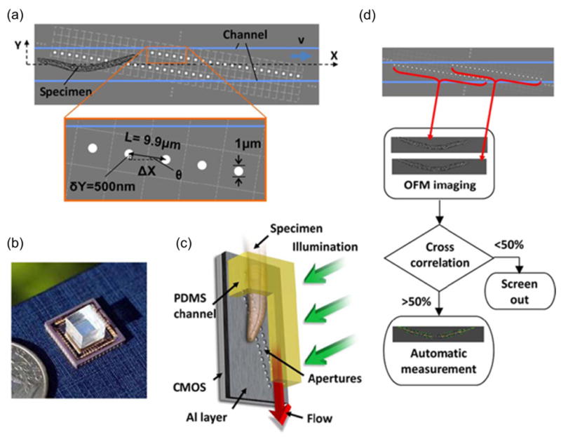
(a) OFM combines microfluidics with aperture based optics. The apertures (white circles) are fabricated on a CMOS sensor array, which span across the microfluidic channel (blue lines). (b) The assembled chip on a CMOS array. (c) The chip can be operated in an upright position to facilitate gravity driven flow and hence to avoid use of external pumps. (d) Flow diagram of OFM operation, which involves comparison between two images (red arrows) acquired by the two OFM arrays. The image pair is accepted if the image correlation is greater than 50%. (adapted from: [43])
The challenges associated with OFM approach include the critical dependence of the imaging outcome on the orientation of the sample and the constant flow rate within the channel. In other words, an acceptable image would not be obtained if the sample orientation during imaging changes (i.e., rotation of the sample during flow). A constant and uniform flow rate needs to be achieved inside the channel for this approach to work effectively, which introduces operational difficulties that is not suitable for resource limited POC applications. On the other hand, the aperture array needs to be in perfect alignment with the underlying sensor grid and the resolution is limited by the size of the apertures and the spacing in between. If these challenges are addressed or minimized with improved design and fabrication methods, OFM microscopy would be suitable for POC since it allows portable operation and does not require expensive peripheral equipment.
3.2. Digital Holography
Digital holography is an emerging phase contrast imaging technique that offers both qualitative and quantitative information [35, 39, 107]. In holographic imaging (Figure 2a), samples are illuminated with a spherical wavefront produced by focusing a laser beam from a 1 μm diameter pinhole (Figure 2b). The focused light serves as a reference beam, while the scattered light serves as an object beam. The CCD sensor array records the interference pattern produced by the superposition of the two wavefronts (the hologram). A subsequent digital elaboration allows retrieving the volume information on the sample from a single 2D hologram (Figure 2c–h). In this method, multiple focal planes can be achieved and captured mimicking the focus control of conventional optical microscopes. Digital holography records the entire object in three-dimensional (3D) space whereas a conventional microscope has a 2D focal plane and requires mechanical scanning to create a full image. Due to the complex analysis that can be performed with holography, the orientation of asymmetric yeast cells can be determined by the broken symmetry as shown in the figure (Figure 2c-h). The resolving power in this method is a function of the hologram recording geometry, the CCD dimensions and incident wavelength.
Figure 2. Digital Holography with lensless ultra wide-field operation.

(a) The photograph of a digital holographic microscope platform. (b) Schematic drawing of the Holographic-microscope platform. (c–e) Microscope images of asymmetric S. pombe yeast cells imaged under 10x objective-lens. (f–h) Detection of the 2D orientation of the cells using Holographic microscope, which are in the same field of view as in (c–e) respectively. (adapted from: [35])
Digital holography has been integrated with fluorescent imaging to achieve lensless fluorescent detection without any thin-film filters or mechanical scanning with an ultra-wide field-of-view (2.5 cm × 3.5 cm) [104]. In this approach, the sample was illuminated with an incoherent excitation beam from an LED or a Xenon lamp source located directly above (Figure 3a). Fluorescent excitation was provided from the side by utilizing a rhomboid prism. The incoherent light beam interacted with the sample and undergoing total internal reflection (TIR) at the bottom (Figure 3a). Detection of the fluorescent emission from the excited cells/particles over the entire FOV of the sensor-array (CCD or CMOS) was achieved without using any lenses. Unlike the traditional fluorescent microscopy, a need for expensive interference filters was not a limiting factor for this method. An inexpensive plastic-based absorption filter was used between the sample and detector planes to achieve a better dark-field background. The issue of potential overlapping of diverged fluorescent emission of cells or particles at the sensor plane was addressed by deconvolving the acquired images, which provided a resolution of ~40–50 μm over the entire sensor FOV without the use of a lens. The system was validated by imaging white blood cells as seen in Figure 3b–h.
Figure 3. Digital Holography integrated with fluorescent imaging.

(a) Wide field lensless fluorescent imaging platform with digital holography. (b)–(e) show the fluorescent imaging of calcein labeled white blood cells and corresponding results using iterative deconvolution algorithm. The cross-sections of fluorescent signatures for the raw lensless image (blue curve) as well as for 100 (green curve) and 600 (red curve) iterations of deconvolution are shown in (g) and (h), respectively. (adapted from: [104])
Digital holography and lensless fluorescent imaging platforms discussed above are innovative approaches that are transforming the microscopy techniques dramatically by simplifying and reducing the cost of imaging equipment. These methods can provide valuable information about the sample, such as the 3D structure and orientation, at the expense of relatively more complex nature, operation and higher computational needs compared to other on-chip imaging technologies (Table 2). Therefore, the aptness and feasibility of utilizing digital holography based approaches in resource-limited POC is questionable and warrants further investigation.
3.3. Lensless Ultra Wide-Field Cell Monitoring Array Platform (LUCAS)
A wide FOV imaging platform would be an alternative to optical microscopes for detection and counting applications, where high resolution is not critical. Therefore, a “lensless, ultra wide-field cell monitoring array platform” has been developed that can be used to detect and count cells on-chip with a two orders of magnitude wider FOV than conventional light microscopes (Figure 4a–b) [13, 15]. This system has been shown to detect and count thousands of individual cells in real time in seconds. LUCAS system is based on recording the “shadow images” of microscale objects onto an optoelectronic sensor array plane. Microscopic objects (e.g., cells) are placed between two microscope glass slides (in a microfluidic device) and are uniformly illuminated with an incoherent white-light source or a laser beam (Figure 4a). Cell shadow pattern is digitally recorded using a CCD sensor array. A CMOS chip, depending on the application type, can also be used as the optoelectronic sensor array. While the former is preferred for applications where image signal-to-noise (S/N) ratio is important, the latter is the sensor of choice for high speed image acquisition. Each cell’s shadow falling onto the sensor array is recorded as object-specific “signatures”. The cell types, assigned with specific signatures, can easily be differentiated and counted (Figure 4c). The distance between the active region of the sensor array (i.e., the active surface of the CCD chip) and the microscopic object location (e.g., cells) is important to optimize LUCAS operation. The shadow diameter is estimated from diffracted light intensity at the sensor plane. Finally, individual cells are computationally modeled as uniform circular objects with a reduced field-transmission coefficient. This technology has recently been modularized with microfluidic devices, paving the way for lensless cell counting technologies at POC applications. A recent study has also demonstrated the potential of this lensless technology for microfluidic based HIV monitoring applications [13].
Figure 4. Integration of Microfluidics with lensless ultra wide-field cell monitoring array platform (LUCAS).
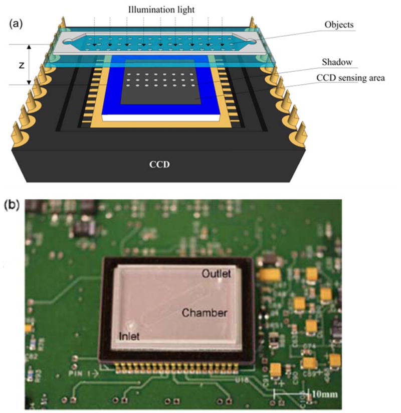
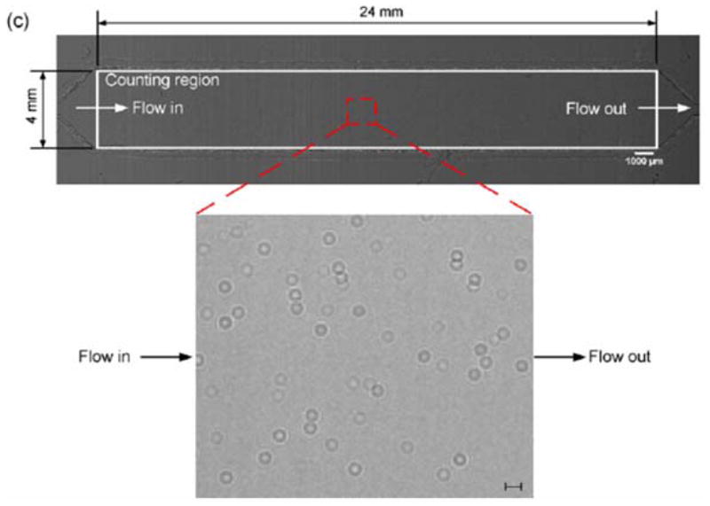
(a) Schematic representation of a microfluidic channel placed on a CCD sensor array. When light is incident on the sample (e.g., cells), the transmitted light is diffracted and the shadows of the samples are captured by the CCD sensor in less than a second. (b) Picture of the microfluidic chip placed on a CCD imaging platform. Field of view of the CCD sensor is 35 mm × 25 mm and therefore, the entire microfluidic device can be imaged without the need for alignment of positioning by simply placing the microfluidic channel on the sensor. (c) Shadows of the captured CD4+ T-lymphocytes captured with the lensless CCD imaging platform. Scale bar is 100 μm. (based on: [13, 15])
4. Conclusions and Perspectives
The needs and challenges in resource-poor POC diagnosis are distinct from the needs and challenges of conventional diagnostics that can be performed at well-equipped settings by well-equipped personnel (Table 1). The essential characteristics of resource-limited POC detection and diagnostic platforms can be listed as: low-cost, functionality, portability, robustness, simplicity, flexibility, ease of use, and sensitivity. Recent advances in on-chip approaches have enabled and facilitated the integration of optics and microfluidics technologies to create new and more effective platforms (Table 2) that are needed at the POC in developing countries. The lensless imaging technologies are best suited for deployment to areas with limited resources. These platforms are promising since they enable rapid detection and counting of thousands of cells of interest, which has already been utilized for rapid CD4+ tests to monitor HIV [13]. The technology provided mainly the HIV diagnostics as an example since it is one of the greater problems of the world. Such technologies combined with surface chemistry can also be used for multiple other diseases including capture of cancer circulating tumor cells [108], detection of other infectious diseases such as sepsis [109] and bacterial pathogens including E. Coli [35]. The advances and approaches discussed in this review may help improve healthcare in developing countries by allowing healthcare personnel to rapidly diagnose and disseminate information and therefore, prevent the spread of communicable diseases. These enabling technologies will potentially shape the future of clinical medicine and will potentially provide solutions for global health problems.
Acknowledgments
This work was performed at the Demirci Bio-Acoustic MEMS in Medicine (BAMM) Labs at the HST-BWH Center for Bioengineering, Harvard Medical School. This work was partially supported by NIH R21 (EB007707) and New Development Grant of the US Department of the Defense (DOD). We would like to acknowledge the Coulter Foundation Young Investigator Award, NIH (R01AI081534), NIH (R21AI087107), the Center for Integration of Medicine and Innovative Technology (CIMIT) under U.S. Army Medical Research Acquisition Activity Cooperative Agreement and the National Natural Science Foundation Young Scholars Research Fund.
Footnotes
6. Conflict of Interest Statement
The authors have declared no conflict of interest.
References
- 1.Wang S, Xu F, Demirci U. Advances in developing HIV-1 viral load assays for resource-limited settings. Biotechnol Adv. 2010;28:770–781. doi: 10.1016/j.biotechadv.2010.06.004. [DOI] [PMC free article] [PubMed] [Google Scholar]
- 2.Laksanasopin T, Chin CD, Moore H, Wang J, et al. Microfluidic Point-of-Care Diagnostics for Resource-Poor Environments. Ieee; New York: 2009. [DOI] [PubMed] [Google Scholar]
- 3.Loubiere S, Moatti JP. Economic evaluation of point-of-care diagnostic technologies for infectious diseases. Clinical Microbiology and Infection. 2010;16:1070–1076. doi: 10.1111/j.1469-0691.2010.03280.x. [DOI] [PubMed] [Google Scholar]
- 4.Usdin M, Guillerm M, Calmy A. Patient Needs and Point-of-Care Requirements for HIV Load Testing in Resource-Limited Settings. Journal of Infectious Diseases. 2010;201:S73–S77. doi: 10.1086/650384. [DOI] [PubMed] [Google Scholar]
- 5.Chin CD, Linder V, Sia SK. Lab-on-a-chip devices for global health: Past studies and future opportunities. Lab Chip. 2007;7:41–57. doi: 10.1039/b611455e. [DOI] [PubMed] [Google Scholar]
- 6.Varmus H, Klausner R, Zerhouni E, Acharya T, et al. Grand challenges in global health. Science. 2003;302:398–399. doi: 10.1126/science.1091769. [DOI] [PMC free article] [PubMed] [Google Scholar]
- 7.Martinez AW, Phillips ST, Whitesides GM, Carrilho E. Diagnostics for the Developing World: Microfluidic Paper-Based Analytical Devices. Analytical Chemistry. 2010;82:3–10. doi: 10.1021/ac9013989. [DOI] [PubMed] [Google Scholar]
- 8.Daar AS, Thorsteinsdottir H, Martin DK, Smith AC, et al. Top ten biotechnologies for improving health in developing countries. Nature Genetics. 2002;32:229–232. doi: 10.1038/ng1002-229. [DOI] [PubMed] [Google Scholar]
- 9.Yager P, Domingo GJ, Gerdes J. Point-of-care diagnostics for global health. Annual review of biomedical engineering. 2008;10:107–144. doi: 10.1146/annurev.bioeng.10.061807.160524. [DOI] [PubMed] [Google Scholar]
- 10.WHO. 2007 UNAIDS annual report: Knowing your epidemic. Joint United Nations Programme on HIV/AIDS (UNAIDS); GENEVA. 2008. [Google Scholar]
- 11.Gilks CF, Crowley S, Ekpini R, Gove S, et al. The WHO public-health approach to antiretroviral treatment against HIV in resource-limited settings. Lancet. 2006;368:505–510. doi: 10.1016/S0140-6736(06)69158-7. [DOI] [PubMed] [Google Scholar]
- 12.Peeling RW, Holmes KK, Mabey D, Ronald A. Rapid tests for sexually transmitted infections (STIs): the way forward. Sexually Transmitted Infections. 2006;82:V1–V6. doi: 10.1136/sti.2006.024265. [DOI] [PMC free article] [PubMed] [Google Scholar]
- 13.Moon S, Keles HO, Ozcan A, Khademhosseini A, et al. Integrating microfluidics and lensless imaging for point-of-care testing. Biosensors & bioelectronics. 2009;24:3208–3214. doi: 10.1016/j.bios.2009.03.037. [DOI] [PMC free article] [PubMed] [Google Scholar]
- 14.Su TW, Seo S, Erlinger A, Ozcan A. High-throughput lensfree imaging and characterization of a heterogeneous cell solution on a chip. Biotechnology and bioengineering. 2009;102:856–868. doi: 10.1002/bit.22116. [DOI] [PMC free article] [PubMed] [Google Scholar]
- 15.Ozcan A, Demirci U. Ultra wide-field lens-free monitoring of cells on-chip. Lab on a chip. 2008;8:98–106. doi: 10.1039/b713695a. [DOI] [PubMed] [Google Scholar]
- 16.Whitesides GM. The origins and the future of microfluidics. Nature. 2006;442:368–373. doi: 10.1038/nature05058. [DOI] [PubMed] [Google Scholar]
- 17.Sia SK, Kricka LJ. Microfluidics and point-of-care testing. Lab Chip. 2008;8:1982–1983. doi: 10.1039/b817915h. [DOI] [PubMed] [Google Scholar]
- 18.Paguirigan AL, Beebe DJ. Microfluidics meet cell biology: bridging the gap by validation and application of microscale techniques for cell biological assays. Bioessays. 2008;30:811–821. doi: 10.1002/bies.20804. [DOI] [PMC free article] [PubMed] [Google Scholar]
- 19.Klapperich CM. Microfluidic diagnostics: time for industry standards. Expert review of medical devices. 2009;6:211–213. doi: 10.1586/erd.09.11. [DOI] [PubMed] [Google Scholar]
- 20.Yager P, Edwards T, Fu E, Helton K, et al. Microfluidic diagnostic technologies for global public health. Nature. 2006;442:412–418. doi: 10.1038/nature05064. [DOI] [PubMed] [Google Scholar]
- 21.Cheng X, Irimia D, Dixon M, Sekine K, et al. A microfluidic device for practical label-free CD4+ T cell counting of HIV-infected subjects. Lab-on-a-Chip. 2007;7:170–178. doi: 10.1039/b612966h. [DOI] [PMC free article] [PubMed] [Google Scholar]
- 22.Cheng X, Irimia D, Dixon M, Ziperstein JC, et al. A Microchip Approach for Practical Label-Free CD4+T-Cell Counting of HIV-Infected Subjects in Resource-Poor Settings. J Acquir Immune Defic Syndr. 2007 doi: 10.1097/QAI.0b013e3180500303. [DOI] [PubMed] [Google Scholar]
- 23.Alyassin MA, Moon S, Keles HO, Manzur F, et al. Rapid automated cell quantification on HIV microfluidic devices. Lab Chip. 2009;9:3364–3369. doi: 10.1039/b911882a. [DOI] [PMC free article] [PubMed] [Google Scholar]
- 24.Lee WG, Kim YG, Chung BG, Demirci U, et al. Nano/Microfluidics for diagnosis of infectious diseases in developing countries. Adv Drug Deliv Rev. 2010;62:449–457. doi: 10.1016/j.addr.2009.11.016. [DOI] [PMC free article] [PubMed] [Google Scholar]
- 25.Moon S, Keles HO, Kim YG, Kuritzkes D, et al. Lensless imaging for point-of-care testing. Conf Proc IEEE Eng Med Biol Soc. 2009;2009:6376–6379. doi: 10.1109/IEMBS.2009.5333765. [DOI] [PMC free article] [PubMed] [Google Scholar]
- 26.Lee WG, Demirci U, Khademhosseini A. Microscale electroporation: challenges and perspectives for clinical applications. Integrative Biology. 2009;1:242–251. doi: 10.1039/b819201d. [DOI] [PMC free article] [PubMed] [Google Scholar]
- 27.Christodoulides N, Floriano PN, Miller CS, Ebersole JL, et al. Lab-on-a-chip methods for point-of-care measurements of salivary biomarkers of periodontitis. In: Malamud D, Niedbala RS, editors. Oral-Based Diagnostics. 2007. pp. 411–428. [DOI] [PubMed] [Google Scholar]
- 28.Christodoulides N, Mohanty S, Miller CS, Langub MC, et al. Application of microchip assay system for the measurement of C-reactive protein in human saliva. Lab Chip. 2005;5:261–269. doi: 10.1039/b414194f. [DOI] [PubMed] [Google Scholar]
- 29.Jokerst JV, McDevitt JT. Programmable nano-bio-chips: multifunctional clinical tools for use at the point-of-care. Nanomedicine. 2010;5:143–155. doi: 10.2217/nnm.09.94. [DOI] [PMC free article] [PubMed] [Google Scholar]
- 30.Jokerst JV, Raamanathan A, Christodoulides N, Floriano PN, et al. Nano-bio-chips for high performance multiplexed protein detection: Determinations of cancer biomarkers in serum and saliva using quantum dot bioconjugate labels. Biosens Bioelectron. 2009;24:3622–3629. doi: 10.1016/j.bios.2009.05.026. [DOI] [PMC free article] [PubMed] [Google Scholar]
- 31.Parsa H, Chin CD, Mongkolwisetwara P, Lee BW, et al. Effect of volume-and time-based constraints on capture of analytes in microfluidic heterogeneous immunoassays. Lab Chip. 2008;8:2062–2070. doi: 10.1039/b813350f. [DOI] [PubMed] [Google Scholar]
- 32.Yang C, Psaltis D. Optofluidics can create small, cheap biophotonic devices. Laser Focus World. 2006;42:85–88. [Google Scholar]
- 33.Ozcan A, Demirci U. Rewritable self-assembled long-period gratings in photonic bandgap fibers using microparticles. Optics Communications. 2007;270:225–228. [Google Scholar]
- 34.Seo S, Su TW, Erlinger A, Ozca A. Multi-color LUCAS: Lensfree On-chip Cytometry Using Tunable Monochromatic Illumination and Digital Noise Reduction. Cellular and Molecular Bioengineering. 2008;1:146–156. [Google Scholar]
- 35.Seo S, Su TW, Tseng DK, Erlinger A, et al. Lensfree holographic imaging for on-chip cytometry and diagnostics. Lab on a chip. 2009;9:777–787. doi: 10.1039/b813943a. [DOI] [PMC free article] [PubMed] [Google Scholar]
- 36.Gopinathan U, Pedrini G, Osten W. Coherence effects in digital in-line holographic microscopy. Journal of the Optical Society of America. 2008;25:2459–2466. doi: 10.1364/josaa.25.002459. [DOI] [PubMed] [Google Scholar]
- 37.Morlens AS, Gautier J, Rey G, Zeitoun P, et al. Submicrometer digital in-line holographic microscopy at 32 nm with high-order harmonics. Optics letters. 2006;31:3095–3097. doi: 10.1364/ol.31.003095. [DOI] [PubMed] [Google Scholar]
- 38.Garcia-Sucerquia J, Xu W, Jericho MH, Kreuzer HJ. Immersion digital in-line holographic microscopy. Optics letters. 2006;31:1211–1213. doi: 10.1364/ol.31.001211. [DOI] [PubMed] [Google Scholar]
- 39.Garcia-Sucerquia J, Xu W, Jericho SK, Klages P, et al. Digital in-line holographic microscopy. Applied optics. 2006;45:836–850. doi: 10.1364/ao.45.000836. [DOI] [PubMed] [Google Scholar]
- 40.Xu W, Jericho MH, Meinertzhagen IA, Kreuzer HJ. Digital in-line holography of microspheres. Applied optics. 2002;41:5367–5375. doi: 10.1364/ao.41.005367. [DOI] [PubMed] [Google Scholar]
- 41.Tulandi T, Huang JY, Tan SL. Preservation of female fertility: an essential progress. Obstet Gynecol. 2008;112:1160–1172. doi: 10.1097/AOG.0b013e31818bba31. [DOI] [PubMed] [Google Scholar]
- 42.Repetto L, Piano E, Pontiggia C. Lensless digital holographic microscope with light-emitting diode illumination. Opt Lett. 2004;29:1132–1134. doi: 10.1364/ol.29.001132. [DOI] [PubMed] [Google Scholar]
- 43.Cui X, Lee LM, Heng X, Zhong W, et al. Lensless high-resolution on-chip optofluidic microscopes for Caenorhabditis elegans and cell imaging. Proceedings of the National Academy of Sciences of the United States of America. 2008;105:10670–10675. doi: 10.1073/pnas.0804612105. [DOI] [PMC free article] [PubMed] [Google Scholar]
- 44.Heng X, Erickson D, Baugh LR, Yaqoob Z, et al. Optofluidic microscopy--a method for implementing a high resolution optical microscope on a chip. Lab Chip. 2006;6:1274–1276. doi: 10.1039/b604676b. [DOI] [PubMed] [Google Scholar]
- 45.Lee LM, Cui X, Yang C. The application of on-chip optofluidic microscopy for imaging Giardia lamblia trophozoites and cysts. Biomedical microdevices. 2009 doi: 10.1007/s10544-009-9312-x. [DOI] [PMC free article] [PubMed] [Google Scholar]
- 46.Brennan D, Justice J, Corbett B, McCarthy T, et al. Emerging optofluidic technologies for point-of-care genetic analysis systems: a review. Analytical and bioanalytical chemistry. 2009;395:621–636. doi: 10.1007/s00216-009-2826-5. [DOI] [PubMed] [Google Scholar]
- 47.Gabor D. A new microscopic principle. Nature. 1948;161:777. doi: 10.1038/161777a0. [DOI] [PubMed] [Google Scholar]
- 48.Masters BR. Correlation of histology and linear and nonlinear microscopy of the living human cornea. J Biophotonics. 2009;2:127–139. doi: 10.1002/jbio.200810039. [DOI] [PubMed] [Google Scholar]
- 49.Schawlow AL, Townes CH. Infrared and Optical Masers. Physical Review. 1958;112:1940–1949. [Google Scholar]
- 50.Psaltis D. Coherent optical information systems. Science. 2002;298:1359–1363. doi: 10.1126/science.1078823. [DOI] [PubMed] [Google Scholar]
- 51.Schubert EF, Kim JK. Solid-state light sources getting smart. Science. 2005;308:1274–1278. doi: 10.1126/science.1108712. [DOI] [PubMed] [Google Scholar]
- 52.Zhang X, Stuart JN, Sweedler JV. Capillary electrophoresis with wavelength-resolved laser-induced fluorescence detection. Anal Bioanal Chem. 2002;373:332–343. doi: 10.1007/s00216-002-1288-9. [DOI] [PubMed] [Google Scholar]
- 53.Kuswandi B, Nuriman, Huskens J, Verboom W. Optical sensing systems for microfluidic devices: A review. Analytica Chimica Acta. 2007;601:141–155. doi: 10.1016/j.aca.2007.08.046. [DOI] [PubMed] [Google Scholar]
- 54.Ryvolova M, Preisler J, Brabazon D, Macka M. Portable capillary-based (non-chip) capillary electrophoresis. Trac-Trends Anal Chem. 2010;29:339–353. [Google Scholar]
- 55.Huber G, Krankel C, Petermann K. Solid-state lasers: status and future. Journal of the Optical Society of America B-Optical Physics. 2010;27:B93–B105. [Google Scholar]
- 56.Kulmala S, Suomi J. Current status of modern analytical luminescence methods. Analytica Chimica Acta. 2003;500:21–69. [Google Scholar]
- 57.Barnes WL, Dereux A, Ebbesen TW. Surface plasmon subwavelength optics. Nature. 2003;424:824–830. doi: 10.1038/nature01937. [DOI] [PubMed] [Google Scholar]
- 58.Link S, El-Sayed MA. Spectral properties and relaxation dynamics of surface plasmon electronic oscillations in gold and silver nanodots and nanorods. Journal of Physical Chemistry B. 1999;103:8410–8426. [Google Scholar]
- 59.Mulvaney P. Surface plasmon spectroscopy of nanosized metal particles. Langmuir. 1996;12:788–800. [Google Scholar]
- 60.Haes AJ, Van Duyne RP. A nanoscale optical blosensor: Sensitivity and selectivity of an approach based on the localized surface plasmon resonance spectroscopy of triangular silver nanoparticles. Journal of the American Chemical Society. 2002;124:10596–10604. doi: 10.1021/ja020393x. [DOI] [PubMed] [Google Scholar]
- 61.Demirel MC, Kao P, Malvadkar N, Wang H, et al. Bio-organism sensingvia surface enhanced Raman spectroscopy on controlled metal/polymer nanostructured substrates. Biointerphases. 2009;4:35–41. doi: 10.1116/1.3147962. [DOI] [PubMed] [Google Scholar]
- 62.Demirci U, Toner M. Direct etch method for microfludic channel and nanoheight post-fabrication by picoliter droplets. Applied Physics Letters. 2006;88:3. [Google Scholar]
- 63.Malvadkar NA, Hancock MJ, Sekeroglu K, Dressick WJ, et al. An engineered anisotropic nanofilm with unidirectional wetting properties. Nat Mater. 2010 doi: 10.1038/nmat2864. advance online publication. [DOI] [PubMed] [Google Scholar]
- 64.Pursel S, Horn MW, Demirel MC, Lakhtakia A. Growth of sculptured polymer submicronwire assemblies by vapor deposition. Polymer. 2005;46:9544–9548. [Google Scholar]
- 65.Xiong X, Busnaina A, Selvarasah S, Somu S, et al. Directed assembly of gold nanoparticle nanowires and networks for nanodevices. Applied Physics Letters. 2007;91:3. [Google Scholar]
- 66.El-Sayed MA. Some interesting properties of metals confined in time and nanometer space of different shapes. Accounts of Chemical Research. 2001;34:257–264. doi: 10.1021/ar960016n. [DOI] [PubMed] [Google Scholar]
- 67.Kelly KL, Coronado E, Zhao LL, Schatz GC. The optical properties of metal nanoparticles: The influence of size, shape, and dielectric environment. Journal of Physical Chemistry B. 2003;107:668–677. [Google Scholar]
- 68.Love JC, Estroff LA, Kriebel JK, Nuzzo RG, et al. Self-assembled monolayers of thiolates on metals as a form of nanotechnology. Chemical Reviews. 2005;105:1103–1169. doi: 10.1021/cr0300789. [DOI] [PubMed] [Google Scholar]
- 69.Rosi NL, Mirkin CA. Nanostructures in biodiagnostics. Chemical Reviews. 2005;105:1547–1562. doi: 10.1021/cr030067f. [DOI] [PubMed] [Google Scholar]
- 70.Ebbesen TW, Lezec HJ, Ghaemi HF, Thio T, et al. Extraordinary optical transmission through sub-wavelength hole arrays. Nature. 1998;391:667–669. [Google Scholar]
- 71.Lezec HJ, Thio T. Diffracted evanescent wave model for enhanced and suppressed optical transmission through subwavelength hole arrays. Optics express. 2004;12:3629–3651. doi: 10.1364/opex.12.003629. [DOI] [PubMed] [Google Scholar]
- 72.Hell SW. Far-field optical nanoscopy. Science. 2007;316:1153–1158. doi: 10.1126/science.1137395. [DOI] [PubMed] [Google Scholar]
- 73.Lewis A, Taha H, Strinkovski A, Manevitch A, et al. Near-field optics: from subwavelength illumination to nanometric shadowing. Nature biotechnology. 2003;21:1378–1386. doi: 10.1038/nbt898. [DOI] [PubMed] [Google Scholar]
- 74.Thio T. A bright future for subwavelength light sources -Generating tiny points of light for such things as storing data on optical disks is aided by a new theory involving evanescent waves. American Scientist. 2006;94:40–47. [Google Scholar]
- 75.Oshikane Y, Kataoka T, Okuda M, Hara S, et al. Observation of nanostructure by scanning near-field optical microscope with small sphere probe. Science and Technology of Advanced Materials. 2007;8:181–185. [Google Scholar]
- 76.Roth JM, Murphy TE, Xu C. Ultrasensitive and high-dynamic-range two-photon absorption in a GaAs photomultiplier tube. Opt Lett. 2002;27:2076–2078. doi: 10.1364/ol.27.002076. [DOI] [PubMed] [Google Scholar]
- 77.Tian Z, Quick NR, Kar A. Laser endotaxy in silicon carbide and PIN diode fabrication. Journal of Laser Applications. 2008;20:106–115. [Google Scholar]
- 78.Bub G, Tecza M, Helmes M, Lee P, et al. Temporal pixel multiplexing for simultaneous high-speed, high-resolution imaging. Nat Meth. 2010;7:209–211. doi: 10.1038/nmeth.1429. [DOI] [PMC free article] [PubMed] [Google Scholar]
- 79.Andersson H, van den Berg A. Microfluidic devices for cellomics: a review. Sensors and Actuators B-Chemical. 2003;92:315–325. [Google Scholar]
- 80.Gardeniers H, Van den Berg A. Micro-and nanofluidic devices for environmental and biomedical applications. International Journalof Environmental Analytical Chemistry. 2004;84:809–819. [Google Scholar]
- 81.Samel B, Nock V, Russom A, Griss P, et al. A disposable lab-on-a-chip platform with embedded fluid actuators for active nanoliter liquid handling. Biomed Microdevices. 2007;9:61–67. doi: 10.1007/s10544-006-9015-5. [DOI] [PubMed] [Google Scholar]
- 82.Sethu P, Mastrangelo CH. Cast epoxy-based microfluidic systems and their application in biotechnology. Sensors and Actuators B-Chemical. 2004;98:337–346. [Google Scholar]
- 83.Tasoglu S, Demirci U, Muradoglu M. The effect of soluble surfactant on the transient motion of a buoyancy-driven bubble. Physics of Fluids. 2008;20 [Google Scholar]
- 84.Tasoglu S, Kaynak G, Szeri AJ, Demirci U, et al. Impact of a compound droplet on a flat surface: A model for single cell epitaxy. Physics of Fluids. 2010;22 doi: 10.1063/1.3475527. [DOI] [PMC free article] [PubMed] [Google Scholar]
- 85.Huh D, Gu W, Kamotani Y, Grotberg JB, et al. Microfluidics for flow cytometric analysis of cells and particles. Physiol Meas. 2005;26:R73–R98. doi: 10.1088/0967-3334/26/3/R02. [DOI] [PubMed] [Google Scholar]
- 86.Douville N, Huh D, Takayama S. DNA linearization through confinement in nanofluidic channels. Analytical and bioanalytical chemistry. 2008;391:2395–2409. doi: 10.1007/s00216-008-1995-y. [DOI] [PubMed] [Google Scholar]
- 87.Huh D, Mills KL, Zhu XY, Burns MA, et al. Tuneable elastomeric nanochannels for nanofluidic manipulation. Nature Materials. 2007;6:424–428. doi: 10.1038/nmat1907. [DOI] [PubMed] [Google Scholar]
- 88.Mills KL, Huh D, Takayama S, Thouless MD. Instantaneous fabrication of arrays of normally closed, adjustable, and reversible nanochannels by tunnel cracking. Lab on a chip. 10:1627–1630. doi: 10.1039/c000863j. [DOI] [PubMed] [Google Scholar]
- 89.Takayama S, Tung YC, Chueh BH, Asme Biological micro/nanofluidics. 2008 [Google Scholar]
- 90.Choi JY, Seo TS. An integrated microdevice for high-performance short tandem repeat genotyping. Biotechnology Journal. 2009;4:1530–1541. doi: 10.1002/biot.200900202. [DOI] [PubMed] [Google Scholar]
- 91.Hattori K, Sugiura S, Kanamori T. On-chip cell culture on a microarray of extracellular matrix with surface modification of poly(dimethylsiloxane) Biotechnology Journal. 2010;5:463–469. doi: 10.1002/biot.201000021. [DOI] [PubMed] [Google Scholar]
- 92.Koo JM, Kleinstreuer C. Liquid flow in microchannels: experimental observations and computational analyses of microfluidics effects. Journal of Micromechanics and Microengineering. 2003;13:568–579. [Google Scholar]
- 93.Neto C, Evans DR, Bonaccurso E, Butt HJ, et al. Boundary slip in Newtonian liquids: a review of experimental studies. Reports on Progress in Physics. 2005;68:2859–2897. [Google Scholar]
- 94.Adiga SP, Brenner DW. Flow control through polymer-grafted smart nanofluidic channels: Molecular dynamics simulations. Nano Letters. 2005;5:2509–2514. doi: 10.1021/nl051843x. [DOI] [PubMed] [Google Scholar]
- 95.Squires TM, Quake SR. Microfluidics: Fluid physics at the nanoliter scale. Reviews of Modern Physics. 2005;77:977–1026. [Google Scholar]
- 96.Yi CQ, Li CW, Ji SL, Yang MS. Microfluidics technology for manipulation and analysis of biological cells. Analytica Chimica Acta. 2006;560:1–23. doi: 10.1016/j.aca.2018.06.054. [DOI] [PubMed] [Google Scholar]
- 97.Chen L, Lee S, Choo J, Lee EK. Continuous dynamic flow micropumps for microfluid manipulation. Journal of Micromechanics and Microengineering. 2008;18 [Google Scholar]
- 98.He X, Hauan S. Microfluidic modeling and design for continuous flow in electrokinetic mixing-reaction channels. Aiche Journal. 2006;52:3842–3851. [Google Scholar]
- 99.Shui L, Eijkel JCT, van den Berg A. Multiphase flow in microfluidic systems -Control and applications of droplets and interfaces. Advances in Colloid and Interface Science. 2007;133:35–49. doi: 10.1016/j.cis.2007.03.001. [DOI] [PubMed] [Google Scholar]
- 100.Pine J, Chow G. Moving live dissociated neurons with an optical tweezer. IEEE Trans Biomed Eng. 2009;56:1184–1188. doi: 10.1109/TBME.2008.2005641. [DOI] [PubMed] [Google Scholar]
- 101.Heng X, Hsiao E, Psaltis D, Yang C. An optical tweezer actuated, nanoaperture-grid based Optofluidic Microscope implementation method. Opt Express. 2007;15:16367–16375. doi: 10.1364/oe.15.016367. [DOI] [PubMed] [Google Scholar]
- 102.Ghosh S, Sharma P, Bhattacharya S. Surface modes of a sessile water drop: an optical tweezer based study. Rev Sci Instrum. 2007;78:115110. doi: 10.1063/1.2816219. [DOI] [PubMed] [Google Scholar]
- 103.Kim YG, Moon S, Kuritzkes DR, Demirci U. Quantum dot-based HIV capture and imaging in a microfluidic channel. Biosensors & bioelectronics. 2009;25:253–258. doi: 10.1016/j.bios.2009.06.023. [DOI] [PMC free article] [PubMed] [Google Scholar]
- 104.Coskun AF, Su TW, Ozcan A. Wide field-of-view lens-free fluorescent imaging on a chip. Lab Chip. 2010;10:824–827. doi: 10.1039/b926561a. [DOI] [PMC free article] [PubMed] [Google Scholar]
- 105.Yang C, Heng X, Cui X, Psaltis D. Optofluidic Microscope-Fitting a Microscope onto a Sensor Chip. Springer; US: 2007. [Google Scholar]
- 106.Lange D, Storment CW, Conley CA, Kovacs GTA. A microfluidic shadow imaging system for the study of the nematode Caenorhabditis elegans in space. Sensors and Actuators B-Chemical. 2005;107:904–914. [Google Scholar]
- 107.Di J, Zhao J, Jiang H, Zhang P, et al. High resolution digital holographic microscopy with a wide field of view based on a synthetic aperture technique and use of linear CCD scanning. Applied optics. 2008;47:5654–5659. doi: 10.1364/ao.47.005654. [DOI] [PubMed] [Google Scholar]
- 108.Stott SL, Lee RJ, Nagrath S, Yu M, et al. Isolation and characterization of circulating tumor cells from patients with localized and metastatic prostate cancer. Sci Transl Med. 2010;2:25ra23. doi: 10.1126/scitranslmed.3000403. [DOI] [PMC free article] [PubMed] [Google Scholar]
- 109.Kotz KT, Xiao W, Miller-Graziano C, Qian WJ, et al. Clinical microfluidics for neutrophil genomics and proteomics. Nat Med. 2010;16:1042–1047. doi: 10.1038/nm.2205. [DOI] [PMC free article] [PubMed] [Google Scholar]