Abstract
Multi-dimensional RF pulses are of current interest due to their promise for improving high field imaging as well as for optimizing parallel transmission methods. One major drawback is that the computation time of numerically designed multi-dimensional RF pulses increases rapidly with their resolution and number of transmitters. This is critical because the construction of multi-dimensional RF pulses often needs to be in real time. The use of graphics processing units for computations is a recent approach for accelerating image reconstruction applications. We propose the use of graphics processing units for the design of multi-dimensional RF pulses including the utilization of parallel transmitters. Using a desktop computer with four NVIDIA Tesla C1060 computing processors, we found acceleration factors on the order of twenty for standard eight-transmitter 2D spiral RF pulses with a 64 × 64 excitation resolution and a ten-microsecond dwell time. We also show that even greater acceleration factors can be achieved for more complex RF pulses.
INTRODUCTION
Multi-dimensional RF pulses are useful in a wide variety of applications including multi-dimensional spatial localization (1), simultaneous spectral-spatial excitation (2), B1+ field inhomogeneity compensation (3), and the mitigation of susceptibility artifacts (4). The use of multiple transmitters (5,6) has been proposed as means of shortening the duration of the RF pulses and reducing the Specific Absorption Rate (SAR). Among the techniques for designing small tip angle multi-dimensional RF pulses (7), the “spatial domain” approach (8,9) calculates the RF pulses by numerically solving a large set of linear equations. The scale of these linear equations increases with the spatial and frequency resolution of the desired magnetization, the k-space sampling, and the number of transmitters. Numerically solving these large-scale linear equations is computationally intensive; the computation takes seconds and often minutes even for a computer equipped with a powerful Central Processing Unit (CPU). This is a major drawback because it is impractical to design pulses in real time while patients wait in the scanner.
A commodity Graphics Processing Unit (GPU) consists of hundreds or thousands of thread processors and is capable of concurrently executing large numbers of multiple arithmetic operations. Using commodity GPUs to accelerate massively parallel applications is a recent technology that has been demonstrated to dramatically accelerate parallel imaging reconstruction applications (10,11). In the spatial domain method, RF pulses are numerically computed by solving the inverse problem of a linear system using algorithms such as Singular Value Decomposition (SVD) or Conjugate Gradient Least Squares (CGLS). Both algorithms are highly parallelizable and are therefore excellent candidates for acceleration using GPUs. Furthermore, a GPU-based computing platform has two major advantages compared to a CPU cluster. One advantage is that CPU clusters are expensive to procure and maintain. A personal computer equipped with four NVIDIA (Santa Clara, CA) Tesla C1060 GPU processors offers four Tera (1012) single-precision Floating Point Operations Per Second (FLOPS) at a cost twenty times lower than a computer cluster with equivalent computing power. The second advantage is that the programming interface, NVIDIA Compute Unified Device Architecture (CUDA) (12), provides a simple and intuitive programming interface that gives users a low learning curve and allows them to easily adopt GPUs to accelerate computations.
In this article, we demonstrate that GPUs can be used to accelerate the design of multi-dimensional RF pulses using the CGLS algorithm and the image domain formulation for parallel transmission. Specifically, four NVIDIA Tesla C1060 GPUs in a high-performance workstation were used to design two-dimensional (2D) spiral RF pulses for eight transmitters. The performance of the CGLS algorithm on the four GPUs was compared to that of single GPU and a quad-core CPU as well. Simulations were performed to compare the final results. We found a twenty-fold acceleration for the design of standard eight-transmitter 2D spiral RF pulses with a 64×64 excitation resolution and a ten μs dwell time going from a single CPU thread to four GPUs. Greater acceleration factors were obtained for RF pulse designs requiring larger matrices.
THEORY
NUMERICAL DESIGN OF PARALLEL TRANSMISSION RF PULSES
The spatial domain method for parallel transmission uses the small-tip-angle approximation to formulate that the desired transverse magnetization m(r) is a linear combination of the magnetization excited by each RF pulse bn(t) on Nc transmitters weighted by their transmission sensitivity sn(r):
| [1] |
Here γ is the gyromagnetic ratio, m0 is the initial magnetization, T is the length of the RF pulses, and k(t) is the k-space trajectory. Discretizing Eq. [1] and solving the inverse problem of the following linear equation solves for the pulses bn:
| [2] |
The desired magnetization m is sampled over Ns spatial points and the bn is discretized into Nt temporal points. The transmission sensitivity for each spatial point is arranged along the diagonal line of the diagonal matrix diag{sn(r)}. Consequently the complex encoding matrix E has Ns rows and Nt columns. By concatenating diag{sn(r)}E horizontally and bn vertically, Eq. [2] can be simplified into the classic form of a linear equation
| [3] |
Here the “coefficient matrix” A = [diag{s1}E, diag{s2}E, …] and the pulse b = [b1, b2, …]H, where H represents the Hermitian transpose. Eq. [3] is generally an ill-posed inverse problem. A soft constraint on the total energy of the RF pulse can be applied using Tikhonov regularization. With a linear regularization term λ included, the optimal RF pulse is the solution to the inverse linear problem
| [4] |
where I is an NcNt ×NcNt identity matrix.
A linear equation such as Eq. [4] can be solved using numerical methods such as SVD or CGLS. The SVD algorithm solves Eq. [4] by inverting the coefficient matrix. Not only is the matrix inversion a computationally intensive O(m3) algorithm, but also the RF pulses designed using this method produce a less accurate profile with more artifacts than those designed using iterative methods such as the CGLS method (13). The CGLS technique finds an approximate solution for the optimization problem
| [5] |
Although the CGLS method is a less computationally intensive O(m2) algorithm, it can require several seconds and even minutes to design multi-dimensional RF pulses for parallel transmission depending on the coefficient matrix size.
GPU ARCHITECTURE
Minimizing the computation time and maximizing the memory access rate can optimize a computing task. A GPU is designed with a massive number of thread processors and high memory bandwidth for intense and highly parallel computations such as 3D graphics rendering. For general-purpose computing, a GPU functions as a coprocessor to accelerate computing tasks by dividing the tasks into sub-tasks, and these sub-tasks are concurrently solved on the multiple thread processors. The NVIDIA CUDA programming model provides an intuitive programming interface that allows a programmer to parallelize a computing task by partitioning the task into multiple computational blocks, and each block consists of multiple threads, the basic elements of the computing task. To use a GPU for general-purpose computations, the data have to be transferred from the system memory to the GPU device memory.
An efficient program should maximize the usage of the GPU memory. The five types of GPU memory are global, register, shared, constant, and texture memories. The GPU global memory provides a high capacity (up to gigabytes) but a bandwidth of hundreds times lower than the registers and shared memory. Registers and shared memory are fast but have a limited capacity (64 kilobytes on NVIDIA Tesla C1060), and on the threads in the same thread block can share variables stored in the shared memory. The constant and texture memory, cached and mostly used for graphics applications, can be utilized to increase the memory bandwidth. In the Methods section, we elaborate on the implementation of RF pulse design and the optimization of the CGLS algorithm on the GPU.
CGLS ALGORITHM WITH REGULARIZATION
The CGLS algorithm is listed below for reference. The implementation on multiple GPUs is described in Appendix.
Initialization:
Iterate until the number of iterations or the convergence tolerance is met:
The notation 1:Ns represents a segment of a vector starting from the first element and ending at the Ns element. The most computationally intensive parts in this algorithm are the matrix-vector products: AH *m, A*d and AH *r. The upper half of the coefficient matrix in Eqn. [6] has Ns rows and Nc×Nt columns and is dense; therefore the vector products need to be explicitly calculated. For operations involved the sparse lower half, only scaling of vectors by λ is needed.
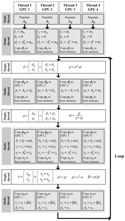
In the CGLS program using the four CPU threads, the computing load was evenly split among the four threads. In the program using the four GPU devices, the four CPU threads were also used with each thread controlling one GPU device, however, the computational load was shifted to the four GPUs. While the coefficient matrix was being computed, the upper half of the coefficient matrix in Eq. [6] was divided into four partitions: AR, AI, −AI, and AR, and stored separately in the global memory of the four GPUs. Following the matrix-vector multiplications described above, a thread barrier was placed such that the computation on all four GPUs could be synchronized. The results from the four separate matrix-vector multiplication, d1, d2, d3, and d4 were copied back to the host memory and combined to one vector d = (d1+d3 d2+d4)T. The real component, d1+d3, was copied back to GPU #1 and #2, and the imaginary component, d2+d4, was copied back to GPU #3 and #4 for the next computation.
It is important to note that using GPUs to accelerate a program introduces overhead, such as creating GPU contexts, allocating memory on GPUs, and transferring data between the host and the GPUs. If the overhead becomes too time-consuming, the benefits of using GPUs for optimization will diminish. On average the overhead time is 300 ms for one GPU and 800 ms for four GPUs. Therefore, the total design time includes the computation of the coefficient matrix, the time to find the solution to the equation using the CGLS algorithm, and the overhead. Even though using multiple threads increased overhead, splitting the computation load among multiple devices still accelerates the arithmetic operations in the CGLS algorithm.
Lastly, the floating-point operations used in this study were in single-precision (SP) format. Current generation GPUs support both SP and double-precision (DP) floating point operations, however SP operations are approximately eight times faster than DP operations on NVIDIA GPUs because in each multiprocessor there are eight SP floating-point arithmetic logic units but only one DP ALU. The storage format of SP floating points on NVDIA graphics hardware is compliant to the IEEE-754 standard, however the arithmetic operations produce slightly different results compared to ones generated on the CPU. In certain instances such as adding a small number to a large one, the results produced on the GPU could deviate from results on the CPU.
METHODS
EXPERIMENT SETUP
The computing platform was a Linux PC running a 2.66 GHz quad-core Intel Xeon processor. Four NVIDIA Tesla C1060 GPU processors were installed in the PCI express 2.0 16-lane slots with a bandwidth of 16 GB/s for each slot. Each GPU had 240 thread processors running at 1.3 GHz. Benchmarks were established for four different CGLS programs written for the computational load allocated to one CPU thread, four CPU threads, one GPU, and four GPUs. A Bloch equation simulator was used to inspect the magnetization patterns excited by the RF pulses to ensure consistency between algorithms. The speed of the computation was determined for six different sized coefficient matrices. The CPU CGLS program used libraries from Basic Linear Algebra Subprograms (BLAS), and the GPU CGLS routine was programmed using the NVIDIA CUDA and CUBLAS libraries.
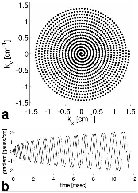
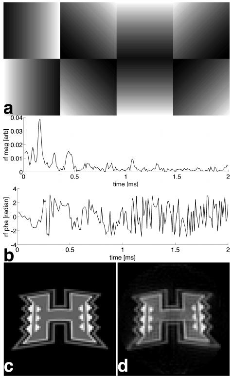
The pulses used a 2D spiral k-space trajectory generated with a 4 gauss/cm peak gradient amplitude, a 12500 gauss/cm/s maximum slew rate, a 22 cm field of excitation (FOX), and a 64×64 matrix resolution. The trajectories and gradients were designed using a custom MATLAB (The MathWorks Inc., Natick, MA) script and stored on the PC. The k-space trajectory is shown in Fig. 1a and the corresponding gradient waveforms are shown in Fig. 1b. The waveform was 11.14 ms long with a dwell time Δt = 10 μs. Figure 2a shows simulated sensitivity maps that were generated to vary linearly across the FOX (rotated 45 degrees for each transmitter). Pulses were then designed using the spatial domain method and a reduction factor of two using all four CGLS programs and six values of Δt equal to 10, 8, 6, 4, 2, and 1.5 μs. The number of CGLS iterations in all calculations was 40, enough to guarantee a good convergence, and the linear regularization constant λ was ten from the inspection of the L-curve. Figure 2b shows the magnitude and phase of the first 200 points of the RF pulse for the first transmitter for Δt = 10 μs designed using a single CPU. The University of Hawaii logo, sampled at a 64×64 resolution and shown in Fig. 2c, was chosen as the desired excitation pattern. Figure 2d shows the simulated magnetization produced by the RF pulse.
Fig. 1.
(a) The spiral k-space trajectory for a 64×64 excitation resolution in a 22 cm FOX. (b) The corresponding gradient waveforms. The solid line is the x gradient, and the dashed line is the y gradient.
Fig. 2.
(a) Simulated transmission sensitivity maps for eight transmitters. (b) The first two hundred points of the magnitude and the phase of the RF pulse for the first coil. (c) The desired 2D excitation pattern. (d) The 2D pattern excited by the RF pulses for eight transmitters using a reduction factor of two.
The dwell time Δt was used as a convenient method to increase the coefficient matrix A size without changing the pulse features. In practice, the size of A is determined by many application dependent parameters including the excitation resolution, the number of k-space points, the number of the transmitters, the number of slices, and the number of frequency points (14). The design of a set of pulses using a single CPU and Δt = 10 μs took approximately fifteen seconds with the size of A equal to 3.6×10⁷. Although this design time is relatively short in duration, this represents a baseline parallel transmission RF pulse design and the computation time increases approximately linearly with the size of the coefficient matrix A. For example, the computation time of the same set of pulses using a single CPU and Δt = 10 μs would be approximately ten minutes in an application that requires ten slices and four frequency points.
IMPLEMENTATION ON GPUs
The complex elements in Eq. [4] were first separated such that the real and imaginary components were grouped into blocks:
| [6] |
where R and I are the real and imaginary components. This equation incorporates the linear regularization therefore the magnetization profile vector m was extended with zeros from the length of Ns to the length of Nc×Nt. The coefficient matrix in Eq. [6] is large (around 600 MB for the Δt = 10 μs pulse) and is time consuming to populate in memory. On a CPU it can take 100 times longer to populate the coefficient matrix than on a GPU. Therefore, it is crucial to populate the coefficient matrix on the GPU and store it in GPU memory.
The lower half of the coefficient matrix in Eq. [6] was a diagonal matrix and was not stored on the GPU memory. However, the upper half of the matrix was dense and needed to be stored on the GPU global memory. The matrix was computed by multiplying the encoding matrix and the diagonal matrix of the sensitivity map. The encoding matrix in turn was the outer product of the k-space trajectory vector and the vector that contained locations of spatial sampling points within FOX. This arithmetic process was computationally intense, approximately equivalent to five iterations of the CGLS routine. Therefore the k-space trajectory and transmission sensitivities were copied into the texture GPU memory as inputs for the computation of the coefficient matrix. Elements along the same column in the encoding matrix read the same value of the k-space trajectory, and the texture memory was optimized for the case when all the threads were reading variables from the same location. The transmission sensitivity was mapped into the spatial location and also stored on the texture memory, which was cached and optimized for repeated access.
RESULTS
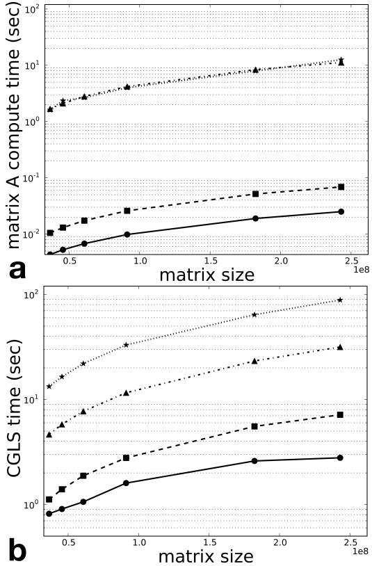
Figure 3a is a logarithmic plot of time used to populate the coefficient matrix, averaged from ten runs, using one CPU thread (stars), four CPU threads (triangles), one GPU (squares), and four GPUs (circles) as a function of the size of the coefficient matrix. Four CPU threads showed no improvement in time over one CPU due to the fact that both use the same host memory. Using visual inspection of the plots, one GPU was able to accelerate this process by a factor on the order of 100 and four GPUs produced a further acceleration by another factor of two. Figure 3b shows the CGLS computation time as a function of the coefficient matrix size. Distributing the computational load to four CPU threads accelerated the algorithm by a factor of approximately three. One GPU was able to accelerate the CGLS routine over that on the single CPU thread by a factor of ten and distributing the computation to four GPUs further accelerated the algorithm by a factor of two to three.
Fig. 3.
(a) Computation time for populating encoding matrices (eight transmitters, 64×64 excitation resolution, reduction factor of two) using one CPU thread (stars), four CPU threads (triangles), one GPU (squares) and four GPUs (circles) as a function of the coefficient matrix size. (b) CGLS computation time as a function of the coefficient matrix size. Coefficient matrices of different sizes were generated using different dwell time for RF pulses.
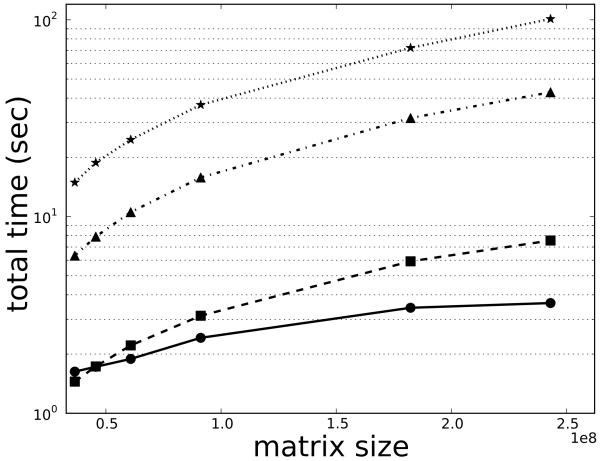
Figure 4 shows the overall computation time as a function of the coefficient matrix size. The overall acceleration was approximately two for the four CPUs threads and ten for one GPU over the single CPU thread. Implementation on four GPUs gained an acceleration factor of twenty over the single CPU thread, however this was only observed for larger encoding matrices and the acceleration diminished as the size of encoding matrix decreased. For smaller encoding matrices, one GPU actually had a higher acceleration factor than four GPUs due to the increased relative overhead.
Fig. 4.
The total compute time to compute RF pulses (eight transmitters, 64×64 excitation resolution, reduction factor of two) using one CPU thread (stars), four CPU threads (triangles), one GPU (squares), and 4 GPUs (circles) as a function of the coefficient matrix size.
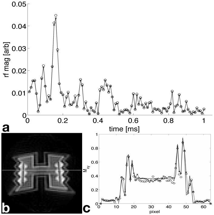
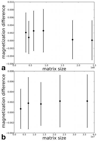
Figure 5a shows the first 100 points of the RF pulse for one of the transmitters. The crosses are data computed by a single CPU thread using DP floating point and the circles are from a single GPU using SP floating point. Figure 5b shows the simulated magnetization generated by the pulse from the single GPU. Figure 5c plots the magnitudes of the magnetization from both the single CPU and GPU evaluated along the line in Fig. 5b. The solid line is the desired magnetization and the crosses are the simulated magnetization from the CPU pulses and circles are from the GPU pulses. The normalized root mean square error (NRMSE) between the desired and simulated magnetizations for the CPU pulses was 0.2720 and for the GPU pulses was 0.2714. Figure 6 shows the mean values and the standard deviations of the differences between the transversal magnetization magnitude obtained from Bloch equation simulations using RF pulses generated on the CPU in DP and the GPU in SP. The points in Fig. 6a are simulated using RF pulses with identical design parameters as those used in Fig. 3 and 4 where the coefficient matrix size was increased using different dwell times of Δt = 10, 8, 6, 4, 2, and 1.5 μs. The Points in Fig. 6b were simulated using pulses with a 10 μs Δt and the coefficient matrix size was varied using 32 × 32, 40 × 40, 48 × 48, 56 × 56, and 64 × 64 excitation resolutions. We found no significant difference between these two designs.
Fig. 5.
(a) The first 100 points of the RF pulse designed on the CPU (crosses) using double-precision floating point and the GPU (circles) using single-precision floating point for the transmitter with first sensitivity map shown in Fig. 2a. (c) The magnetization magnitude along the line in (b) excited by the CPU pulse (crosses) and the GPU pulse (circles).
Fig. 6.
The mean values and the standard deviations of the differences between the magnetization magnitudes produced by Bloch equation simulation using pulses generated on the CPU using DP and on the GPU using SP. All points have same pulse parameters except in (a) the RF dwell time (Δt = 10, 8, 6, 4, 2, and 1.5 μs) and (b) the excitation resolution (N = 32, 40, 48, 56, and 64) were changed to vary the coefficient matrix size.
DISCUSSION AND CONCLUSIONS
In conclusion, we implemented a CGLS algorithm for parallel transmission RF pulse design, using the small tip angle spatial domain method, on four NVIDIA Tesla C1060 GPUs. The method uses easily accessible libraries and standard routines and does not require any low level programming. We found an acceleration factor of 20 for eight-transmitter 2D spiral RF pulses with a 64×64 excitation resolution and a10-μs dwell time when going from a single CPU thread to four GPUs. We also found that greater acceleration factors can be achieved for larger-scale problems that involve much more advanced RF pulse designs. Although we used 2D spiral pulses for proof of concept, the underlying numerical method is identical for the design of all multi-dimensional RF pulses including “fast-kz” 3D pulses for signal loss reduction (15) and 4D spectral-spatial pulses (16). The design of these pulses can take minutes on a CPU. The proposed approach should also accelerate the computation of large flip angle multi-dimensional pulses for parallel transmission (17,18). In this application, the forward and backward integrations of the Bloch equation are the most compute-intensive part in the optimal control approach for nonlinear RF pulse designs. The evolution of the spin magnetization at each spatial location can be computed independently and parallelized on the GPU thread processors.
In general the implementation of CGLS in SP offers higher speed but lower numerical accuracy. We found that the GPU implementation in SP using the small-tip-angle approach produces slightly different RF waveforms than pulses generated using DP on the CPU. However, the implementation in SP produced identical results on the CPU and the GPU. The difference is primarily the result of lower numerical accuracy of SP. We also found that the difference in the simulated magnetization profiles from small-tip-angle SP pulses and DP pulses was negligible. However, in other pulse design algorithms the result using SP can be significantly different than the DP result, and implementation in DP or mixed precision might be necessary. For example. we found in separate studies that large-tip-angle designs using optimal control approaches do require higher numerical accuracy. A general suggestion would be to investigate the numerical accuracy of SP before the implementation of the algorithm on GPUs.
We showed that two steps in the RF pulse design, the computation of coefficient matrix and the CGLS algorithm, can be accelerated using four GPUs over one CPU by factors on the order of 200 and 20, respectively. However, as mentioned above, the overhead introduced from using multiple CPU threads to access multiple video cards is around 800 ms. Amdahl’s law states that the maximum acceleration using parallel computing is 1/((1-p) + p/s), where p is the part of the program that can be optimized via parallelization, and s is the acceleration factor. Thus we would estimate the limit of acceleration using four NVIDIA Telsa C1060 cards is t1/200 + t2/20 + 0.8 seconds, where t1 is the computing time for populating coefficient matrix and t2 is the computing time for the CGLS routine using a single CPU thread. This result shows qualitative agreement with what we observe. The acceleration factor will be even higher using GPUs to design more complicated RF pulses. In practice, creating GPU compute context and allocating GPU memory once and reusing them for the design of multiple sets of RF pulses can reduce the overhead. However, if the coefficient matrix is small enough that the computational overhead on the GPU becomes substantial, using multiple host CPU threads in the CGLS routine becomes more advantageous than using GPUs. Furthermore, using multiple GPUs is the solution for the design of RF pulses when the coefficient matrix size exceeds the memory capacity of a single GPU. The GPUs used in this study were based on NVIDIA G80 chip family, which usually have more than 512 MB of onboard memory (ours had 4 GB). We found that 512 MB memory was sufficient to design pulses with a 64 × 64 excitation resolution and a reduction factor of two (150 gauss/cm/s slewrate and 4 gauss/cm gradient amplitude) for eight transmitters.
The proposed method can be easily transferred to image reconstruction using numerical inverse approaches including multiple receiver coils (19,20). The numerical method of SENSE for parallel image reconstruction is identical to the spatial domain method for parallel transmission and requires solving a similar inverse linear problem. In practice, the CG method is sometimes preferred for its speed over the CGLS method. This is because each CGLS iteration includes a matrix-vector multiplication and a transposed matrix-vector multiplication, whereas each CG iteration has only one matrix-vector multiplication. Even though the CG method requires a symmetric matrix, it can be applied to solve the linear equation: , and this symmetric matrix only needs to be computed once for all the images. A GPU computer system is also flexible to upgrade compared with conventional clusters. More GPU cards can be installed into a workstation for imaging applications that acquire larger data sets. With vendors striving to pack more computation power on graphics cards and competing for market shares, GPUs will keep up to meet the computational demands in parallel imaging as an affordable and promising solution.
Acknowledgments
Work supported by the National Institute on Drug Abuse (R01DA019912, K02DA020569). Core resources supported by the National Center for Research Resources (G12-RR003061, P20-RR011091), National Institute of Neurological Disorders and Stroke (U54-NS56883), and the Office of National Drug Control Policy
Appendix
Figure A.
displays a flowchart detailing the implementation of the CGLS algorithm on multiple GPUs. The context for each GPU is created in the local scope of each thread and the computing load is distributed onto GPUs. The gray boxes are segments of CGLS that can be parallelized, and the white boxes are vector norm operations, which require copying parts of vector d, p, and s into system memory and calculating the sums in one CPU thread.
References
- 1.Hardy CJ, Cline HE. Spatial localization in two dimensions using NMR designer pulses. J Magn Reson. 1989;82:647–654. [Google Scholar]
- 2.Meyer CH, Pauly JM, Macovski A, Nishmura DG. Simultaneous spatial and spectral selective excitation. Magn Reson Med. 1990;15:287–304. doi: 10.1002/mrm.1910150211. [DOI] [PubMed] [Google Scholar]
- 3.Saekho S, Boada FE, Noll DC, Stenger VA. A small tip angle 3D tailored RF slab-select pulse for reduced B1 inhomogeneity at 3T. Magn Reson Med. 2005;53:479–484. doi: 10.1002/mrm.20358. [DOI] [PMC free article] [PubMed] [Google Scholar]
- 4.Stenger VA, Boada FE, Noll DC. Three-dimensional tailored RF pulses for the reduction of susceptibility artifacts in T2*-weighted functional MRI. Magn Reson Med. 2000;44:525–531. doi: 10.1002/1522-2594(200010)44:4<525::aid-mrm5>3.0.co;2-l. [DOI] [PMC free article] [PubMed] [Google Scholar]
- 5.Katscher U, Bornert P, Leussler C, van den Brink J. Transmit SENSE. Magn Reson Med. 2003;49(1):144–150. doi: 10.1002/mrm.10353. [DOI] [PubMed] [Google Scholar]
- 6.Zhu Y. Parallel excitation with an array of transmit coils. Magn Reson Med. 2004;51(4):775–784. doi: 10.1002/mrm.20011. [DOI] [PubMed] [Google Scholar]
- 7.Pauly JM, Nishimura D, Macovski A. A k-space analysis of small-tip-angle excitation. J Magn Reson. 1989;81:43–56. doi: 10.1016/j.jmr.2011.09.023. [DOI] [PubMed] [Google Scholar]
- 8.Yip CY, Fessler JA, Noll DC. Iterative RF pulse design for multidimensional, small-tip-angle selective excitation. Magn Reson Med. 2005;54(4):908–917. doi: 10.1002/mrm.20631. [DOI] [PubMed] [Google Scholar]
- 9.Grissom W, Yip CY, Zhang Z, Stenger VA, Fessler JA, Noll DC. Spatial domain method for the design of RF pulses in multicoil parallel excitation. Magn Reson Med. 2006;56(3):620–629. doi: 10.1002/mrm.20978. [DOI] [PubMed] [Google Scholar]
- 10.Hansen MS, Atkinson D, Sorensen TS. Cartesian SENSE and k-t SENSE reconstruction using commodity graphics hardware. Magn Reson Med. 2008;59(3):463–468. doi: 10.1002/mrm.21523. [DOI] [PubMed] [Google Scholar]
- 11.Sebastien Roujol BDdS, Vahala Erkki. Online real-time reconstruction of adaptive TSENSE with commodity CPU/GPU hardware. Magn Reson Med. 2009;62:1658–1664. doi: 10.1002/mrm.22112. [DOI] [PubMed] [Google Scholar]
- 12.NVIDIA . NVIDIA compute unified device architecture programming guide. 2.3 ed. 2009. [Google Scholar]
- 13.Adam C, Zelinski LLW, Setsompop Kawin, Alagappan Vijaynand, Gagoski Borjan A., Goyal Vivek K, Herbank Franz, Fontius Ulrich, Schmitt Franz, Adalsteinsson Elfar. Comparison of three algorithms for solving linearized systems of parallel excitation RF waveform design equations: experiments on an eight-channel system at 3 Tesla. Concepts in Magn Reson B. 2007;31B(3):176–190. [Google Scholar]
- 14.Setsompop K, Alagappan V, Gagoski BA, Potthast A, Hebrank F, Fontius U, Schmitt F, Wald LL, Adalsteinsson E. Broadband slab selection with B1+ mitigation at 7T via parallel spectral-spatial excitation. Magn Reson Med. 2009;61(2):493–500. doi: 10.1002/mrm.21834. [DOI] [PMC free article] [PubMed] [Google Scholar]
- 15.Yip CY, Fessler JA, Noll DC. Advanced three-dimensional tailored RF pulse for signal recovery in T2*-weighted functional magnetic resonance imaging. Magn Reson Med. 2006;56(5):1050–1059. doi: 10.1002/mrm.21048. [DOI] [PubMed] [Google Scholar]
- 16.Yang C, Deng W, Alagappan V, Wald L, Stenger V. Four-dimensional spectral-spatial RF pulses for simultaneous correction of B1+ inhomogeneity and susceptibility artifacts in T2*-weighted MRI. Magn Reson Med. doi: 10.1002/mrm.22471. in press. [DOI] [PMC free article] [PubMed] [Google Scholar]
- 17.Xu D, King KF, Zhu Y, McKinnon GC, Liang ZP. Designing multichannel, multidimensional, arbitrary flip angle RF pulses using an optimal control approach. Magn Reson Med. 2008;59(3):547–560. doi: 10.1002/mrm.21485. [DOI] [PMC free article] [PubMed] [Google Scholar]
- 18.Grissom WA, Yip CY, Wright SM, Fessler JA, Noll DC. Additive angle method for fast large-tip-angle RF pulse design in parallel excitation. Magn Reson Med. 2008;59(4):779–787. doi: 10.1002/mrm.21510. [DOI] [PubMed] [Google Scholar]
- 19.Sutton BP, Noll DC, Fessler JA. Fast, iterative image reconstruction for MRI in the presence of field inhomogeneities. IEEE Trans Med Imaging. 2003;22(2):178–188. doi: 10.1109/tmi.2002.808360. [DOI] [PubMed] [Google Scholar]
- 20.Pruessmann KP, Weiger M, Bornert P, Boesiger P. Advances in sensitivity encoding with arbitrary k-space trajectories. Magnetic Resonance in Medicine. 2001;46:638–651. doi: 10.1002/mrm.1241. [DOI] [PubMed] [Google Scholar]


